Week 14 challenge
Assemble and apply GD&T to the butterfly valve assembly drawing
Note: While doing the submission all the part files to be sent along with the assembly file in a single folder.
AIM:
To assemble the Butterfly Valve by using the sub parts created and apply the GD&T to the Butterfly Valve assembly drawing.
Introduction:
Butterfly Valve:
- A butterfly valve is a valve that isolates or regulates the flow of a fluid. The closing mechanism is a disk that rotates. A butterfly valve is from a family of valves called quarter-turn valves. In operation, the valve is fully open or closed when the disc is rotated a quarter turn.
- The "butterfly" is a metal disc mounted on a rod. When the valve is closed, the disc is turned so that it completely blocks off the passageway. When the valve is fully open, the disc is rotated a quarter turn so that it allows an almost unrestricted passage of the fluid. The valve may also be opened incrementally to throttle flow. The image of Butterfly Valve is shown below
Geometric Dimensioning and Tolerancing (GD&T):
Geometric Dimensioning and Tolerancing is a system for defining and communicating engineering tolerances. It uses symbolic language on engineering drawings and computer-generated three-dimensional solid models that explicitly describe nominal geometry and its allowable variation. It tells the manufacturing staff and machines what degree of accuracy and precision is needed on each controlled feature of the part. GD&T is used to define the nominal (theoretically perfect) geometry of parts and assemblies, to define the allowable variation in form and possible size of individual features, and to define the allowable variation between features. There are several standards available worldwide that describe the symbols and define the rules used in GD&T. One such standard is the American Society of Mechanical Engineers (ASME) Y14.5
Design methodology Flowchart:
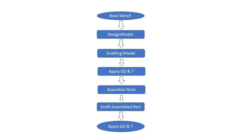
Parts of Butterfly Valves:-
1] Main Body of Butterfly Valve
2] Shaft
3] Retainer
4] Disc Plate
5] Nut
6] Screw
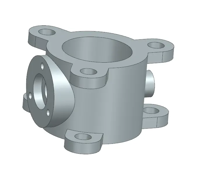
Body:
- The body is the housing for the internal components, and it is the main part of the butterfly valve. The body connects to two pipes on its two sides, and it regulates to flow. For the creation of this part, simple features like revolve, extrude, and move objects are used in the modeling application of NX. The image of Body is shown below
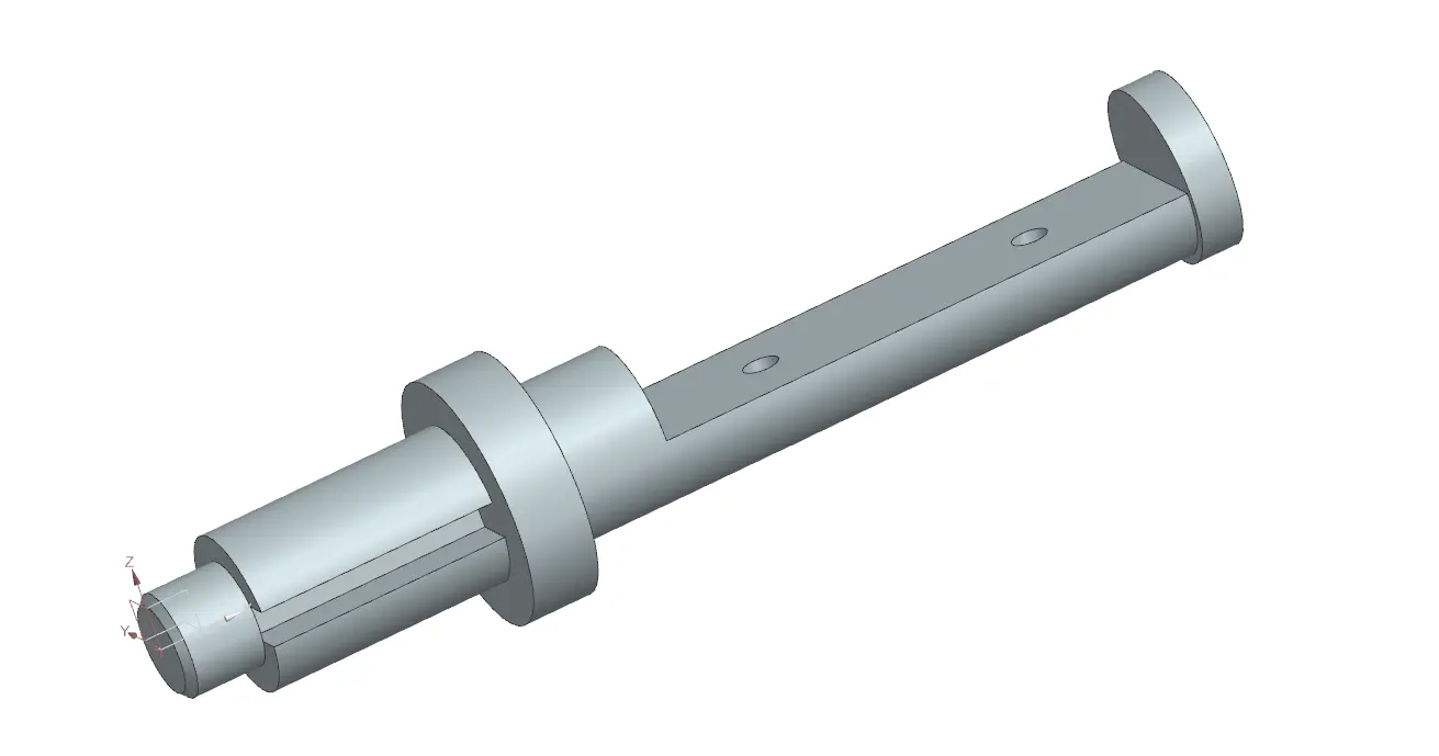
Shaft/Stem:
- It is another important component of the butterfly valve. It inserts into the body of the valve and sits perpendicular to the direction of flow. It holds the disc inside the body and is clamped with the lever outside the body. It is created using simple features like revolve and extrudes features in the NX modeling environment. The image of Shaft/Stem is shown below
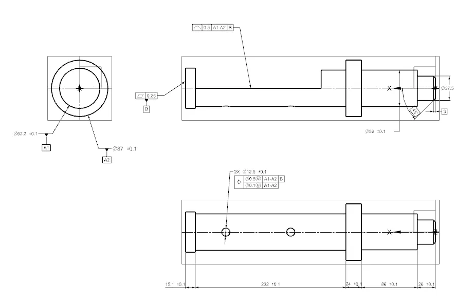
- GD&T applied drawing of shaft/stem:
Disc Plate:
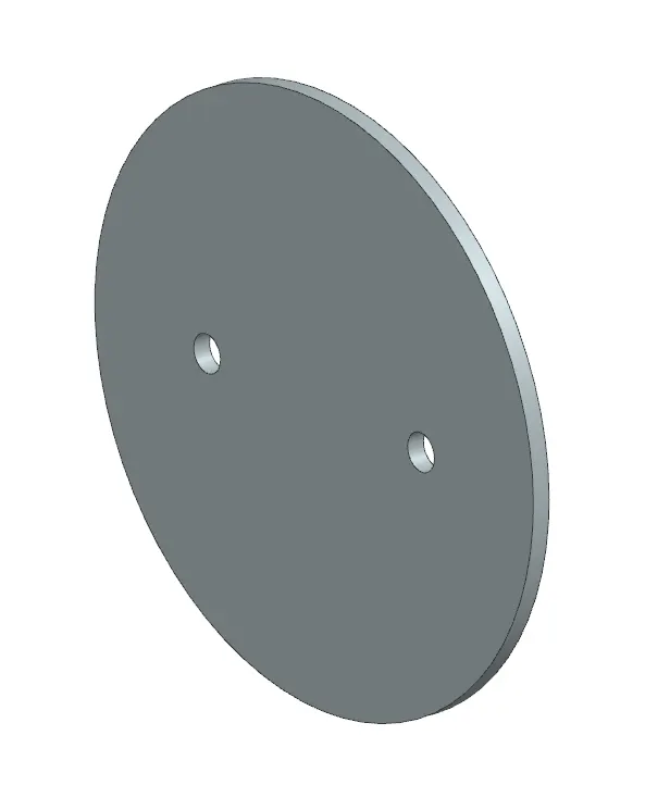
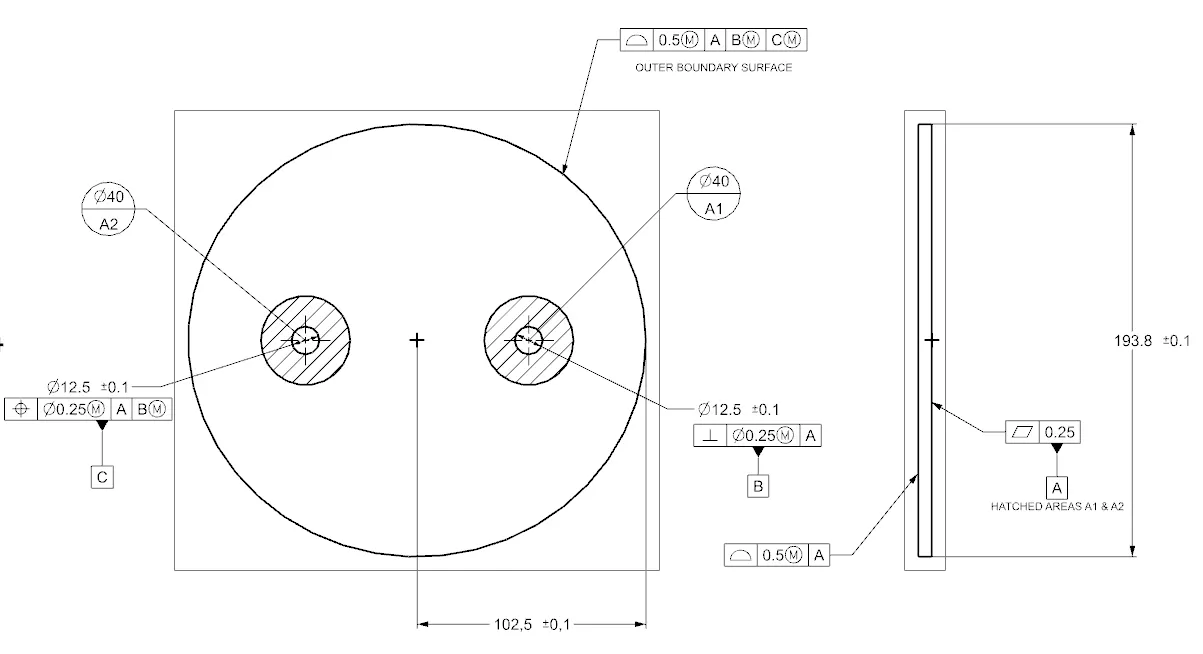
- This disc plate is the main component of the butterfly valve which regulates the flow in the valve. The orientation of this disc determines the flow rate of the fluid. It is not perfectly circular, rather it is elliptical in profile. The holes in it help to position it properly on the shaft created earlier. A simple feature like extrude can create this part in NX. The image of Disc Plate is shown below
- GD&T applied drawing of disc plate:
Retainer:
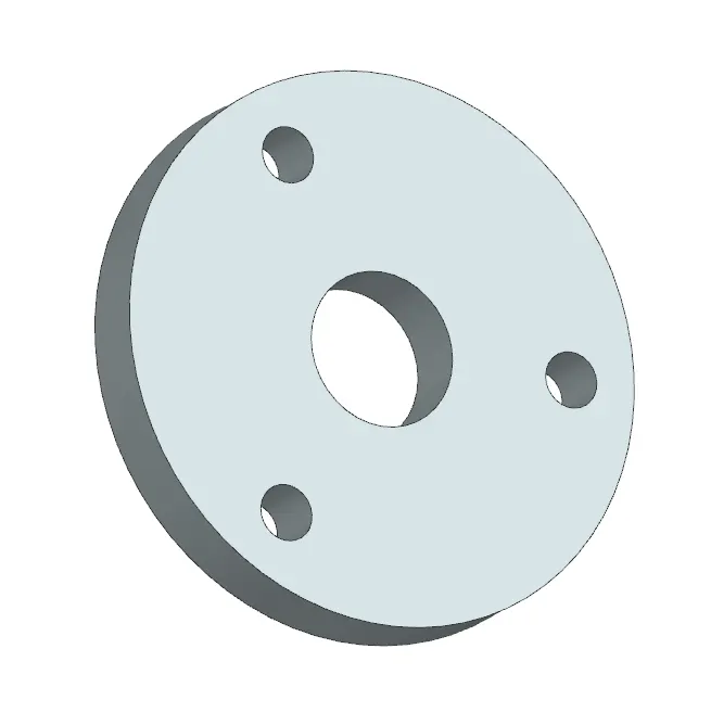
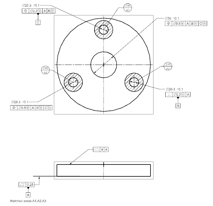
- This part helps to retain or to fix the shaft with the body of the butterfly valve. It prevents the shaft from coming out of the body and keeps it in position for the proper functioning of the disc inside the body. The creation of the retainer plate involves only a simple feature like extrude in NX. The image of Retainer is shown below
GD&T applied drawing of retainer :
Lever:
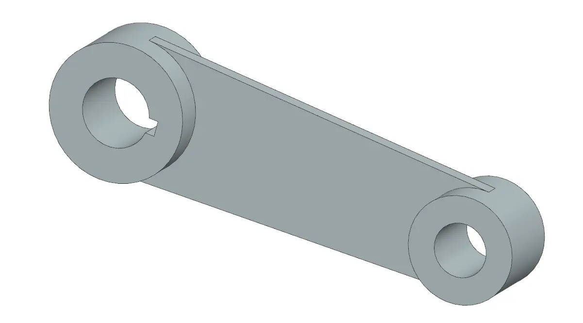
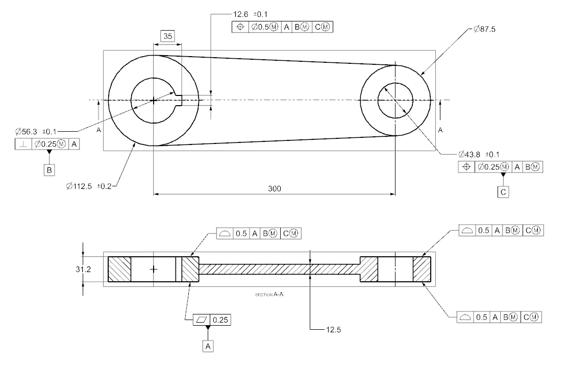
- A lever is a handle that is used to rotate in order to regulate the flow. It is attached to the shaft with the help of a key to fixing it in position with respect to it. So when it is rotated, the shaft rotates which in turn rotates the disc and regulates the flow inside the pipe.It is created using simple features like extrude in NX after the proper base sketch is created.The image of Lever is shown below
GD&T applied drawing of lever :
Nut:
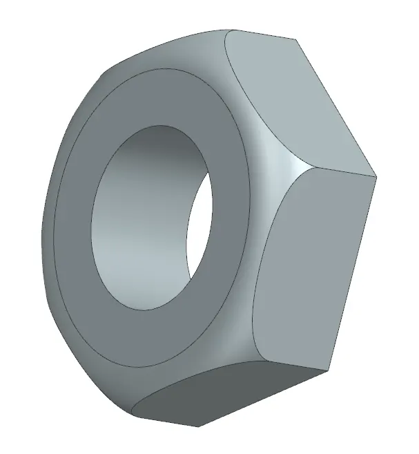
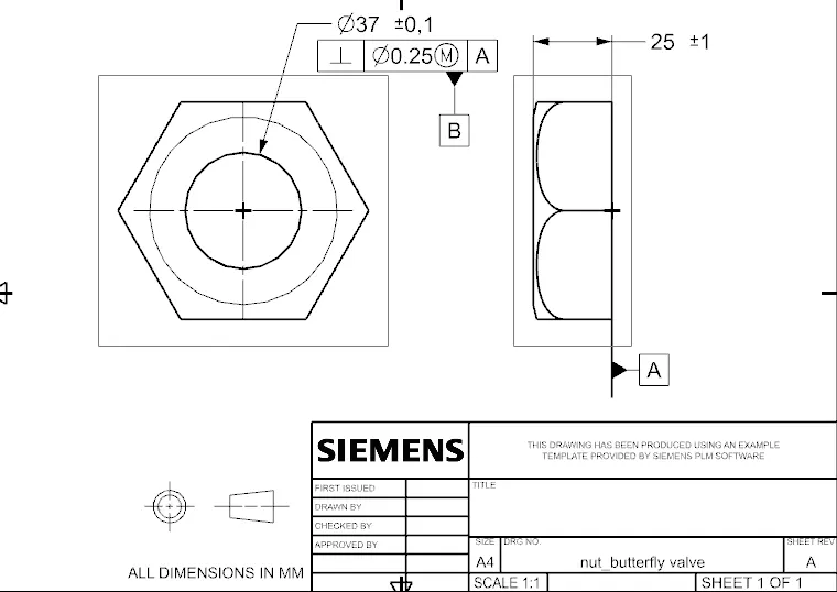
- It is the last part that helps to fix the lever in position with the stem.It allows to keep it in position or to disassemble whenever required.It is created using simple extrude and revolve features in NX. The image of Nut is shown below
GD&T applied drawing of nut :
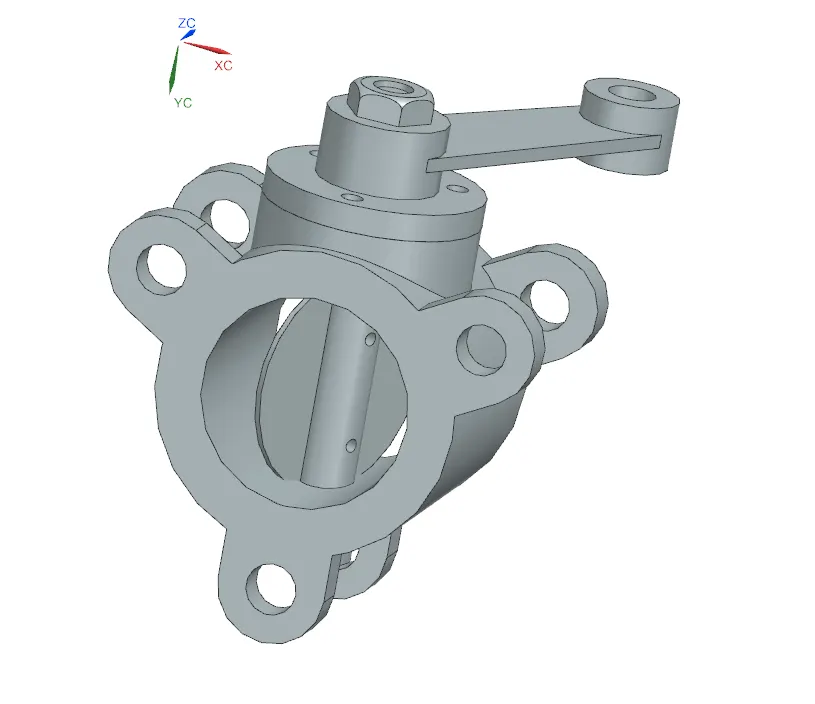
ASSEMBLY :
- The assembly is created by first adding all the sub parts in assemble sheet in NX.
- Then the shaft and disc are joined together in place to create a sub-assembly.
- Then that shaft disc assembly is then assembled to the body.
- Then retainer plate is assembled with the body
- Then the lever is assembled to the shaft in a position that is then fixed.
- Then the nut is assembled with the shaft.
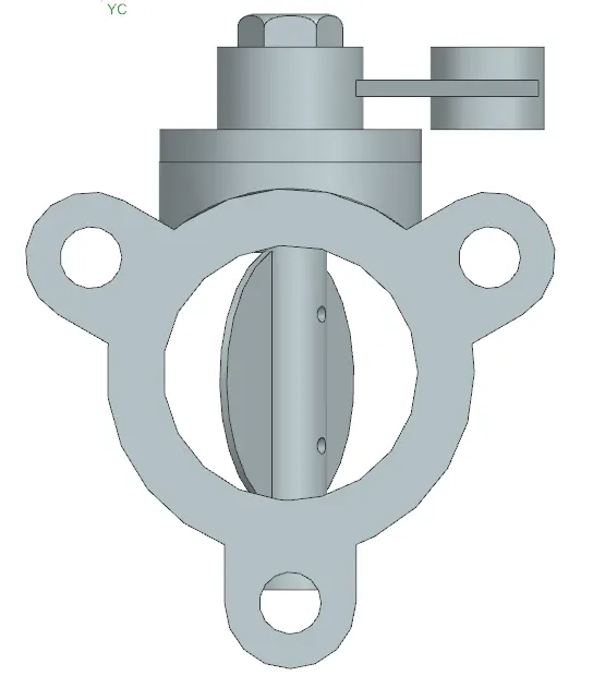
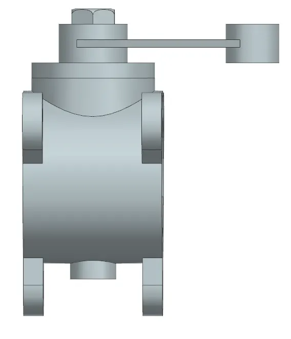
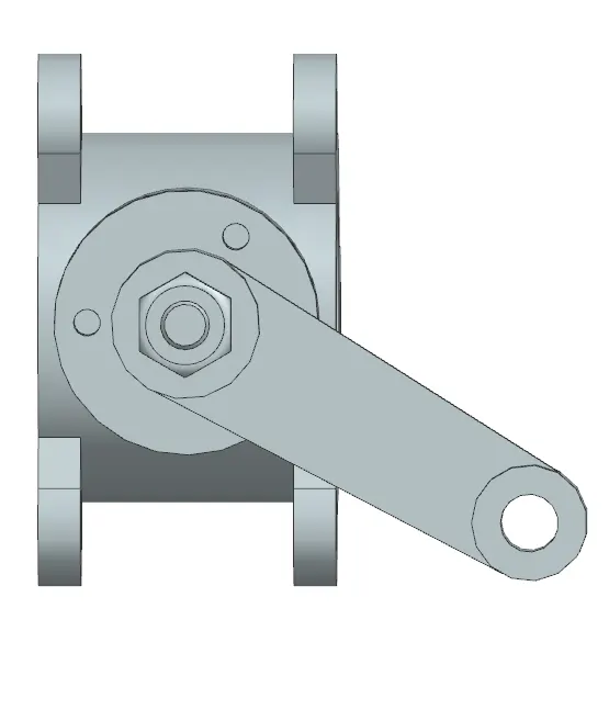
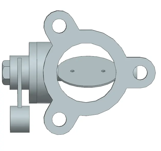
The image of Butterfly Valve Assembly is shown below:
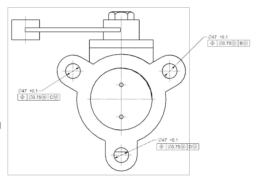
gd&t applied drawings of butterfly assembly:
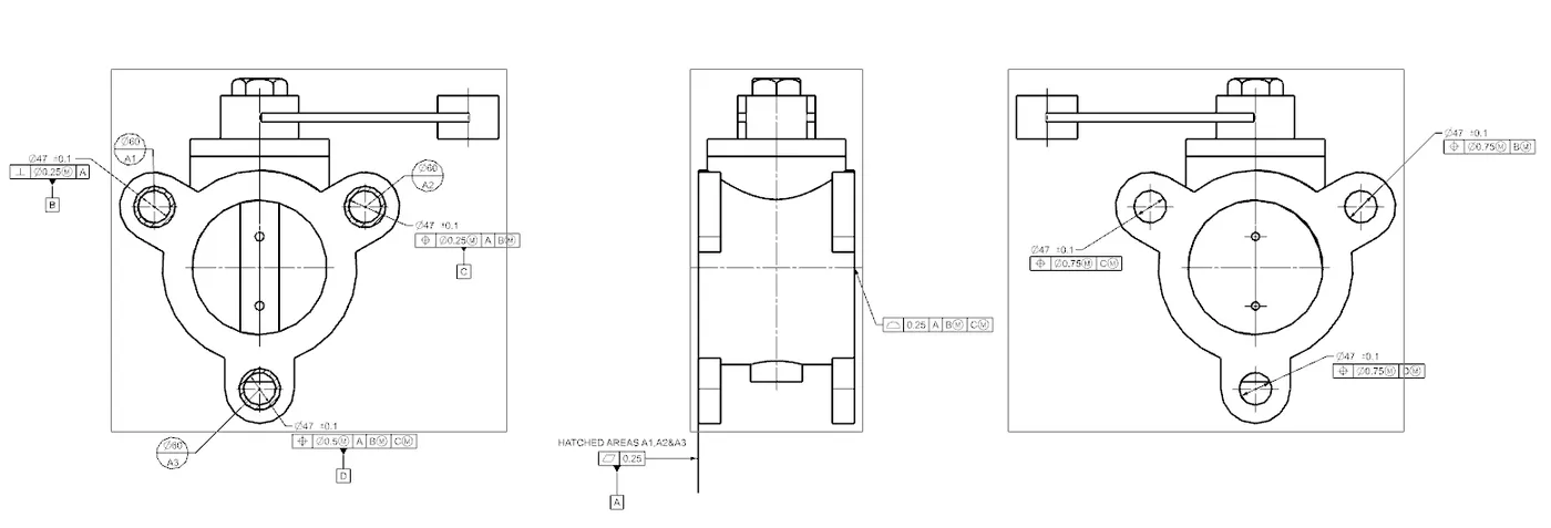
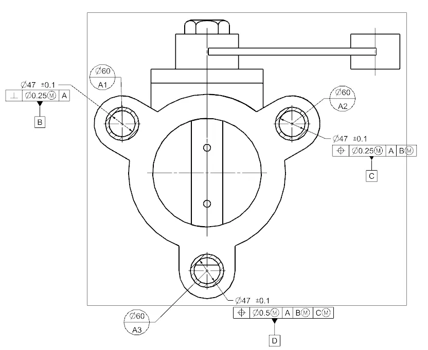
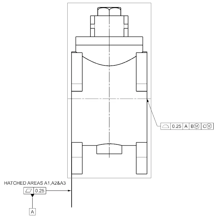
CONCLUSION
The butterfly valve was successfully designed, and GD&T was applied to all parts and the assembly of the butterfly valve.