Week 14 challenge
Report:
The aim of this project is to devise a butterfly valve and implement Geometric Dimensioning and Tolerancing (GD&T) to its constituent parts and final assembly using Siemens NX software.
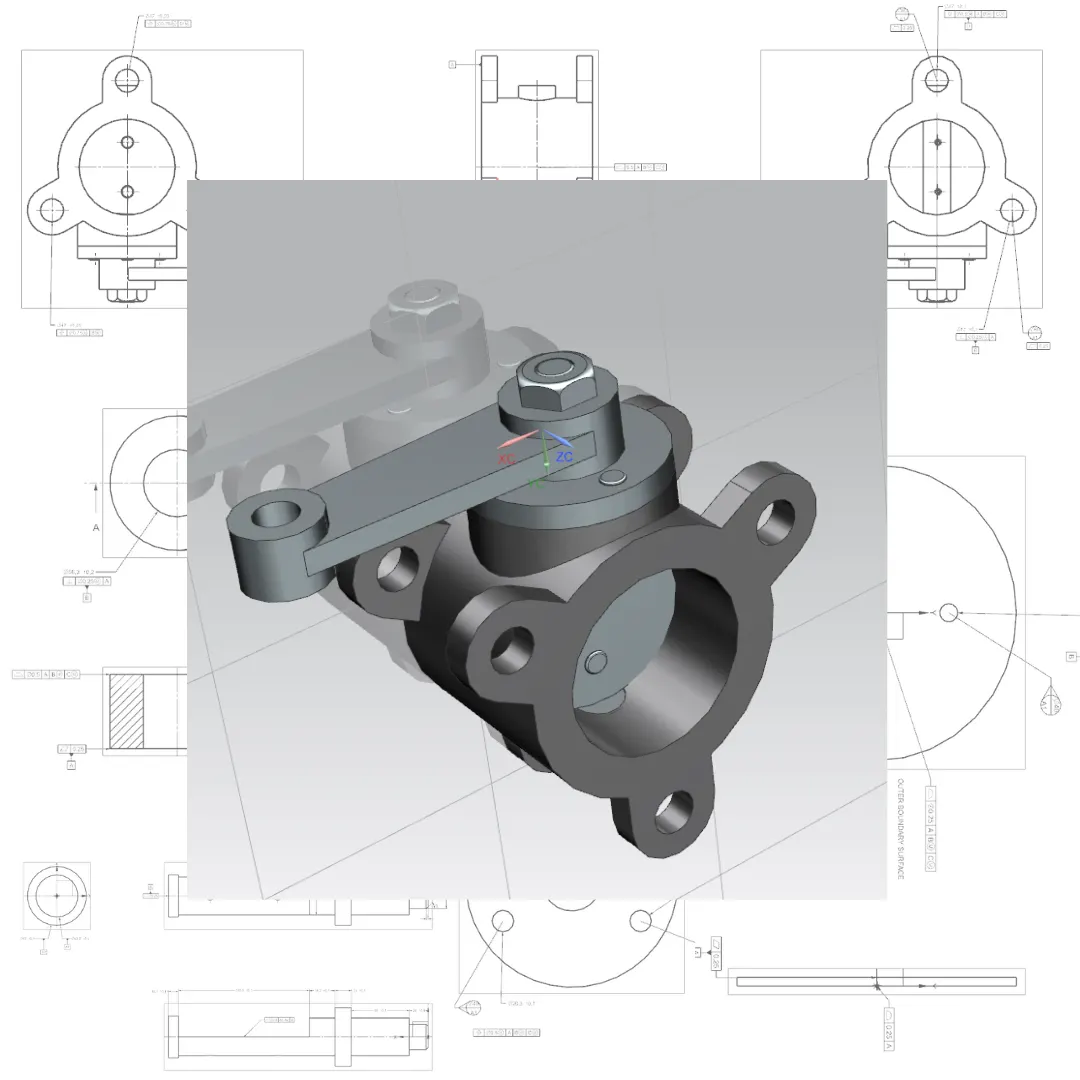
Introduction:
A butterfly valve belongs to the family of quarter-turn valves. During operation, the valve achieves complete openness or closure by rotating the disc a quarter turn. The "butterfly" denotes a metal disc affixed to a shaft. When shut, the disc pivots to entirely obstruct the passageway; whereas in the fully open position, it permits near-unrestricted fluid flow. Additionally, the valve can be adjusted incrementally to regulate flow. Various types of butterfly valves cater to different pressures and applications.
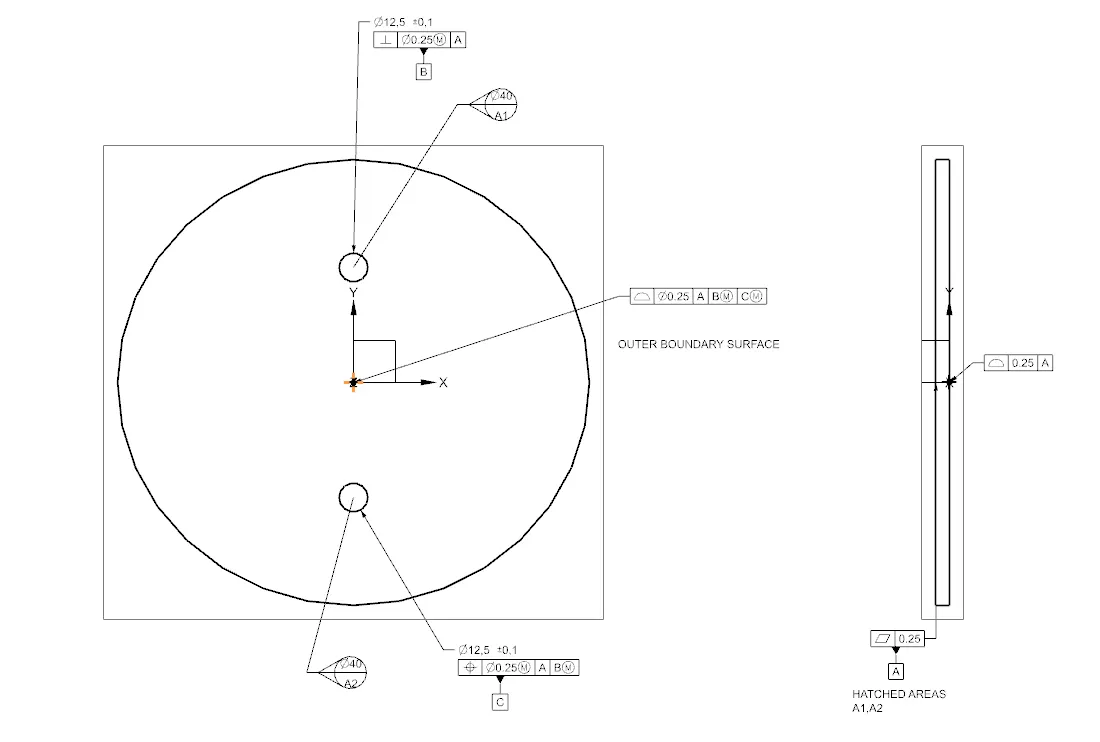
Following the modeling of diverse butterfly valve components, GD&T principles are applied to each part and the final assembly. GD&T, a system for delineating and communicating engineering tolerances, employs a symbolic language on engineering drawings and three-dimensional solid models to explicitly define nominal geometry and permissible variation. This facilitates conveying the required accuracy and precision to manufacturing personnel and machinery. GD&T defines nominal geometry, allowable variation in form and size of features, and permissible deviation between features.
Several global standards elucidate symbols and regulations utilized in GD&T. The American Society of Mechanical Engineers (ASME) Y14.5 is one such standard, offering comprehensive GD&T guidelines within a single document. While this article adheres to the ASME standard, other standards like those from the International Organization for Standardization (ISO) may exhibit slight variations. Typically, ISO standards address individual topics whereas ASME Y14.5 covers a broader spectrum.
Components of Butterfly Valve:
Below are the various components of the butterfly valve along with applied GD&T:
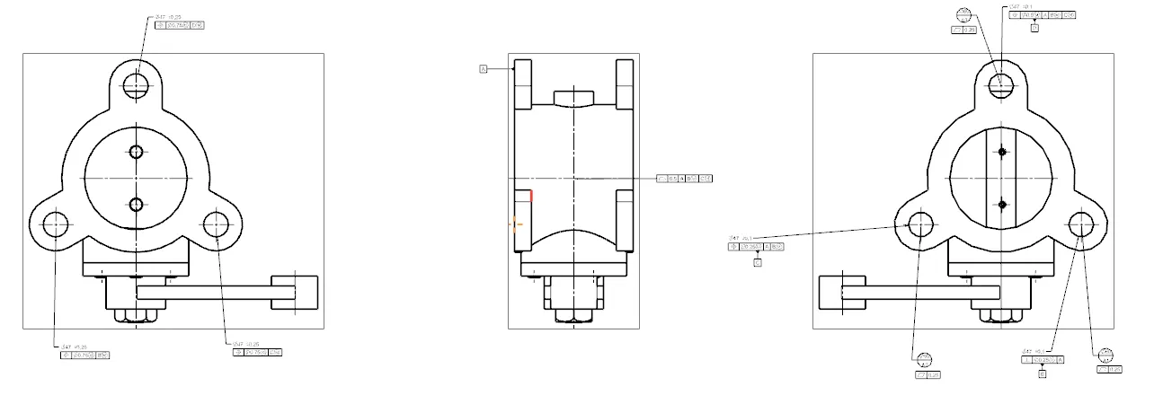
1. Body - Butterfly Valve: The body of a butterfly valve is typically sandwiched between two pipelines using flange couplings. The body and its GD&T application using Siemens NX CAD are illustrated below.
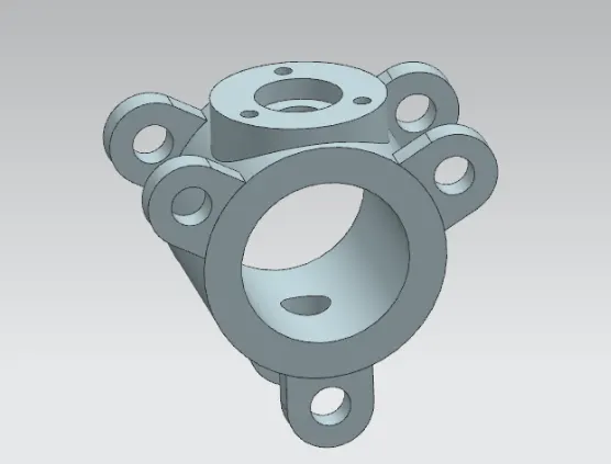
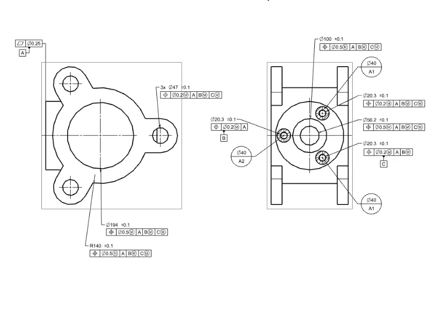
2. Shaft - Butterfly Valve: This shaft houses the disc/plate, lever, and nut assembly.
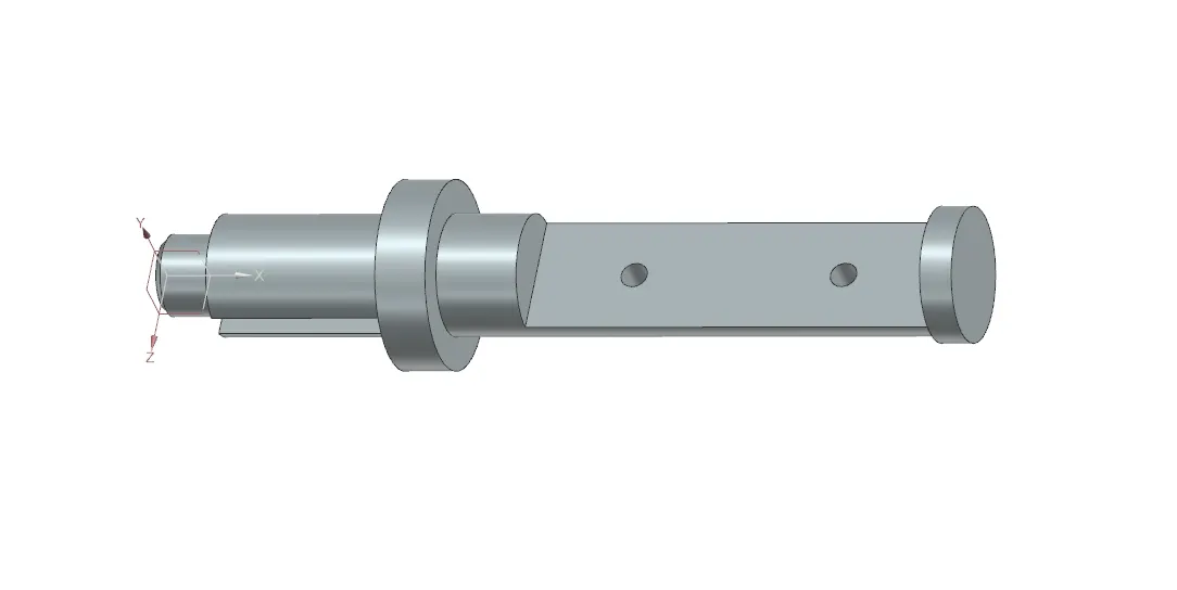
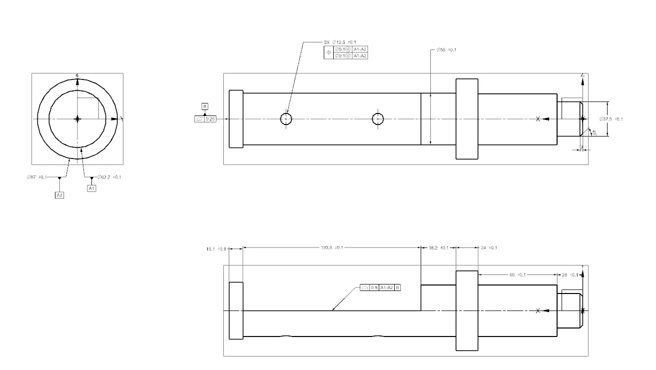
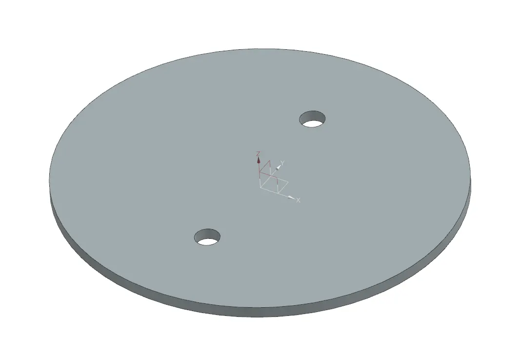
3. Disc - Butterfly Valve: The disc rotates a quarter turn to fully open or close the valve. It is mounted on the shaft and blocks or allows fluid passage accordingly.
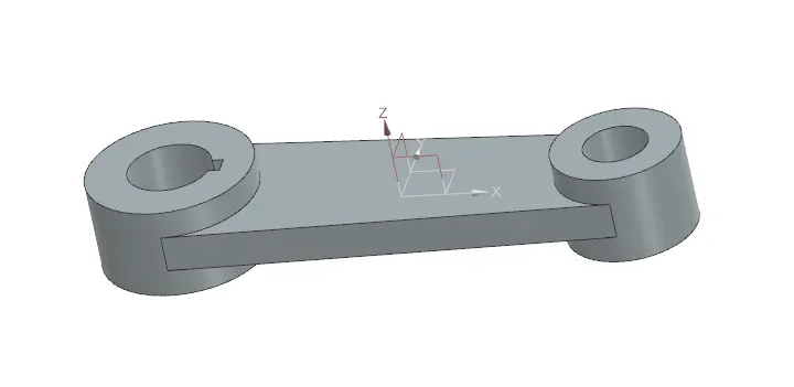
4. Lever - Butterfly Valve: Positioned at one end of the shaft outside the body, the lever, commonly employed in smaller butterfly valves, facilitates valve operation by opening or closing it.
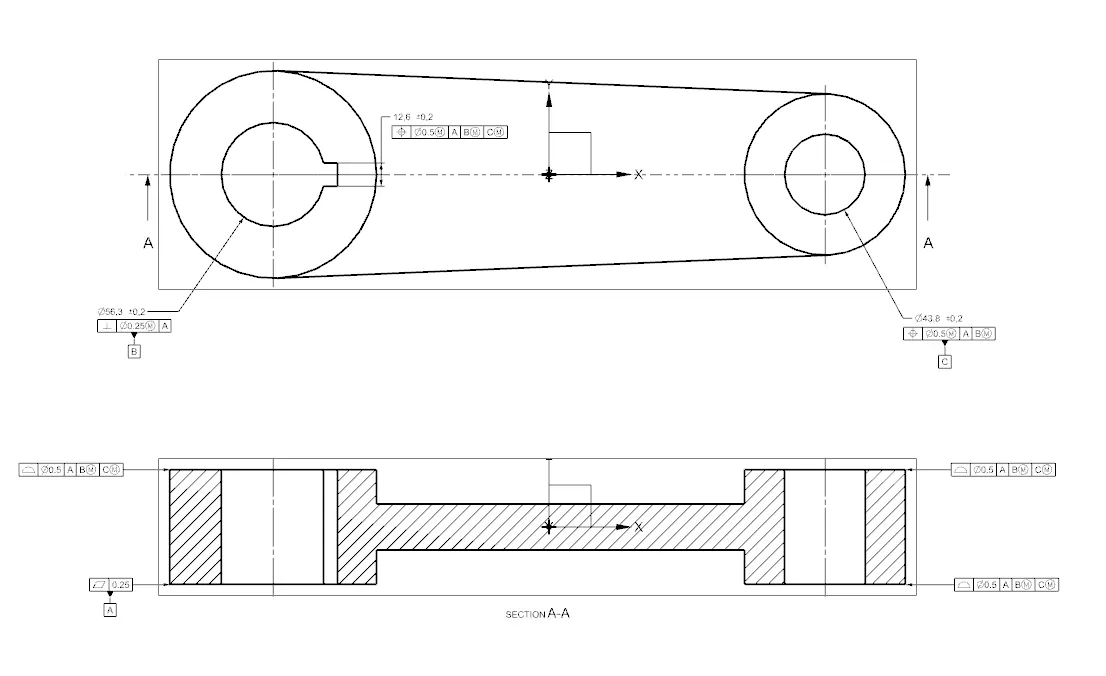
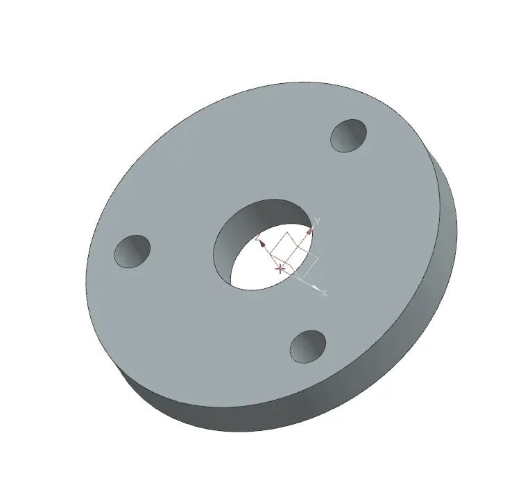
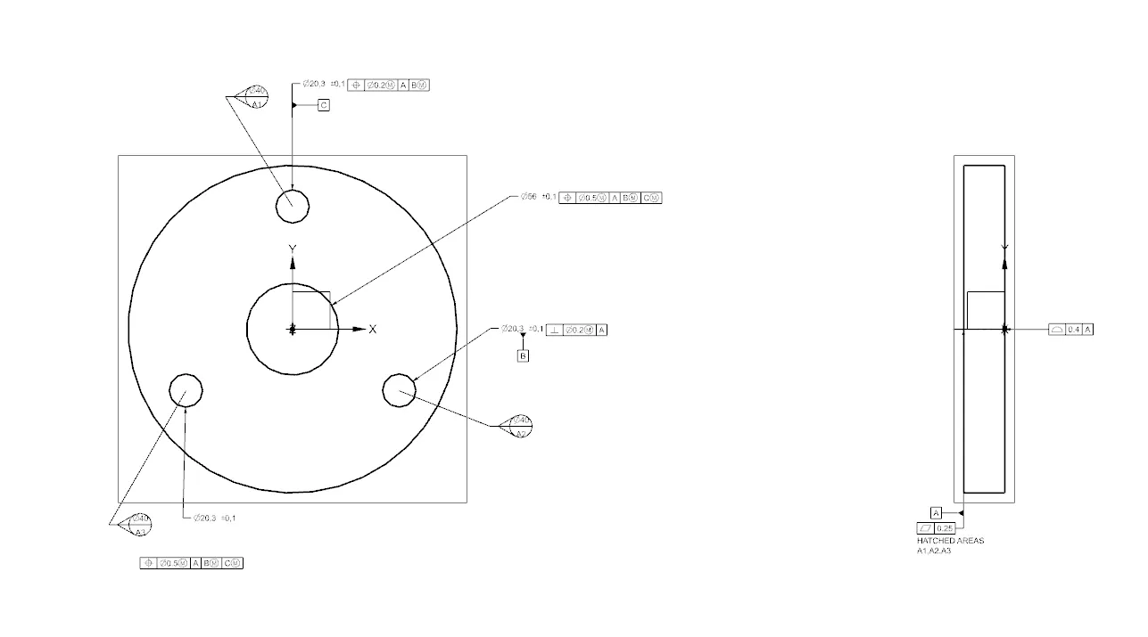
5. Retainer - Butterfly Valve: A washer type retainer affixed to the valve body.
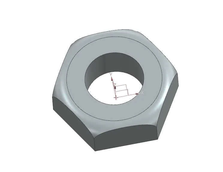
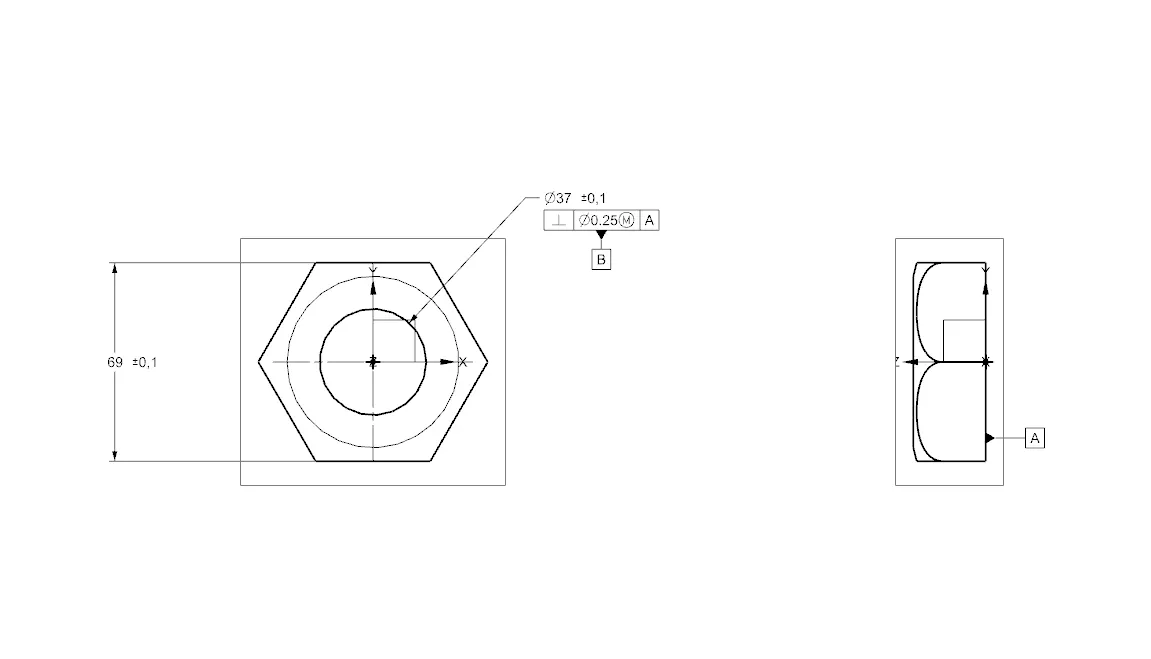
6. Nut - Butterfly Valve: Fixed at the shaft's top end to secure the lever and retainer relative to the valve body.
Assembly - Butterfly Valve:
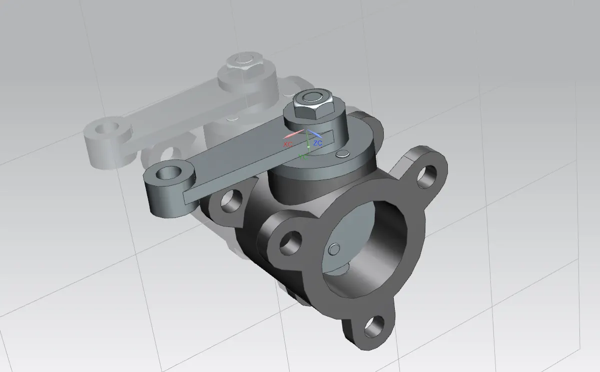
Upon completing the modeling of individual components, all parts are assembled using Siemens NX Assembly workbench.
Conclusion:
The butterfly valve was successfully designed with GD&T principles applied to all parts and the assembly, ensuring precision and functionality.