Week 14 challenge
BUTTERFLY VALVE ASSEMBLY:
A butterfly valve is a quarter-turn valve that initiates throttling and flows control of fluids. Given its name, you can easily visualize a thin metal disc that "flutters" about a fixed axis (stem assembly). The opening and closing mechanism allows and restrict the flow of a medium between an upstream and downstream pipe. A 90° rotation of the handle provides a complete closure or opening of the valve. Large Butterfly valves are usually equipped with a so-called gearbox, where the handwheel by gears is connected to the stem. This simplifies the operation of the valve, but at the expense of speed.
COMPONENTS OF BUTTERFLY VALVE ASSEMBLY:
1)BODY:
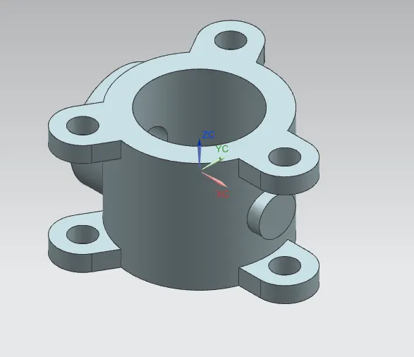
utterfly Valve has one of the major components that is a body that is fit between two pipe flanges. The body is the housing for the internal components and it is the main part of the butterfly valve. The body connects to two pipes on its two sides and it regulates to flow. For the creation of this part, simple features like to revolve, extrude, and move objects are used in the modeling application of NX.
2)SHAFT:
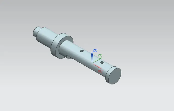
It is another important component of the butterfly valve. It inserts into the body of the valve and sits perpendicular to the direction of flow. It holds the disc inside the body and is clamped with the lever outside the body. It is created using simple features like revolve and extrudes features in the NX modeling environment. After the part creation is completed, the drawing is created in the drafting application of NX, and GD&T is applied using the features of NX. For this shaft, position tolerance should be given to the holes which hold the disc, a profile of the surface should be applied to the surface where the disc sits, and position tolerance for the cylindrical body of the shaft concerning the defined datums. Composite position tolerance is applied in the case of disc positioning holes as it repeats creating a pattern.
3)DISC PLATE:
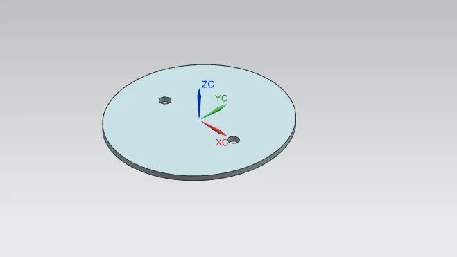
This disc plate is the main component of the butterfly valve which regulates the flow in the valve. The orientation of this disc determines the flow rate of the fluid. It is not perfectly circular, rather it is elliptical in profile. The holes in it help to position it properly on the shaft created earlier. A simple feature like extrude can create this part in NX. To apply GD&T for this part, the primary datum is defined on the surface where it comes in contact with the surface of the shaft, and perpendicular and perpendicular tolerances are applied as per the requirement. As the cost increases, while machining the entire contact surface, small circular datum targets are created and GD&T is applied to reduce the manufacturing cost
4)RETAINER:
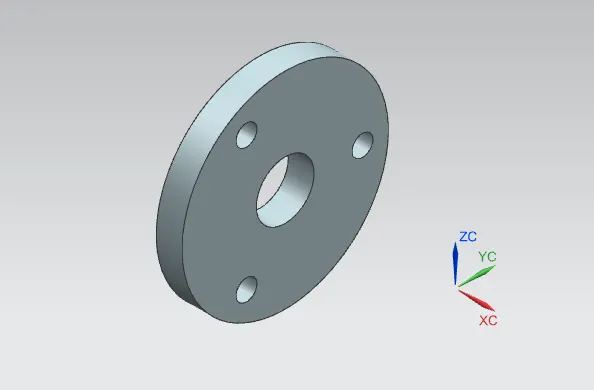
This part helps to retain or to fix the shaft with the body of the butterfly valve. It prevents the shaft from coming out of the body and keeps it in position for the proper functioning of the disc inside the body. The creation of the retainer plate involves only a simplefeature like extrude in NX. For the GD&T application in the retainer plate, similar steps are followed as in the case of the disc. Primary, secondary and tertiary datums are defined properly as per the design intent, and datum targets are applied to the holes. Perpendicular and position tolerances are applied to lock the DOF of the retainer in position. A profile tolerance is also applied to control the upper
5)LEVER HANDLE:
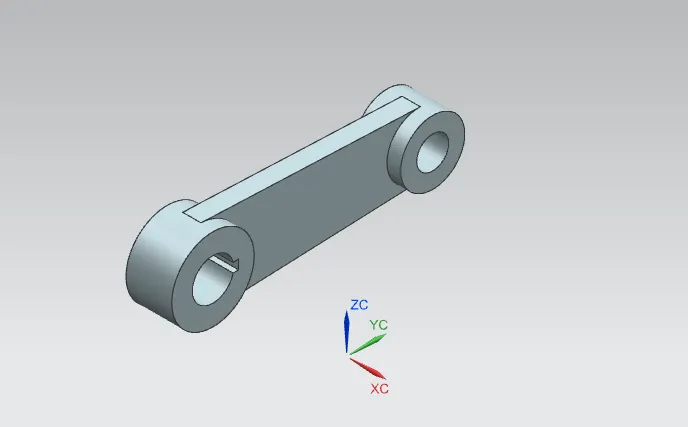
Basically lever handle is used to open and close the Butterfly Valve. It provides ease of operation at the expense of speed. It can be adjusted to various positon with the help of the gearbox.
A lever is a handle that is used to rotate to regulate the flow. It is attached to the shaft with the help of a key to fixing it in position concerning it. So when it is rotated, the shaft rotates which in turn rotates the disc and regulates the flow inside the pipe. It is createdusing simple features like extrude in NX after the proper base sketch is created. For the application of GD&T on the lever, a section view is also created to show how different datums are defined and tolerances are provided. Position tolerance is applied to the proper holes after the perpendicular tolerance is applied to the first hole. To control the key slot, small tolerance is applied to the width of it. Profile tolerances are provided to the surfaces which come to contact with other parts as per the requirement.
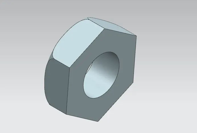
6)NUT:
It is the last part that helps to fix the lever in position with the stem. It allows to keep it in position or to disassemble whenever required. It is created using simple extrude and revolve features in NX. To apply GD&T for this nut, the primary datum is defined on the surface which comes in contact with the lever. Perpendicular tolerance is applied to the hole or the thread and is defined as datum B. Size tolerance is also applied to the thickness of the nut.
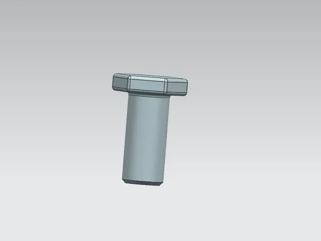
7)BOLT:
A bolt is a type of fastener that is used to hold two or more mechanical components either stationary or under motion. It requires a nut to get fastened. That’s why a nut and bolt are said to be a pair that is used to hold different components. We in our daily life don’t think about bolts and their types but without nuts and bolts assembly of various mechanical components would have been difficult.A bolt is pushed into a predrilled hole and a nut is fastened from the other side. It is fastened or loosened typically by fastening or loosening the nut with the help of spanners.
ASSEMBLY OF PART BODY:
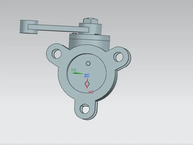
The assembly is created by first placing the body in position and mating other parts to it with the application of different joints provided in NX. First, the shaft and disc are joined together with the screws in place to create a sub-assembly which is then joined to the body in position. The retainer plate is then mated with the body and screws are used to fix them. After that, the lever is mated to the shaft in a position that is then fixed after the nut is mated with the shaft.
DRAFTING DIAGRAM:
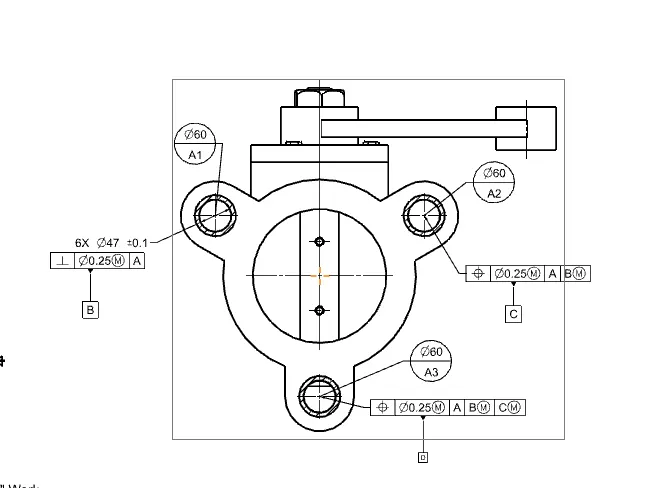
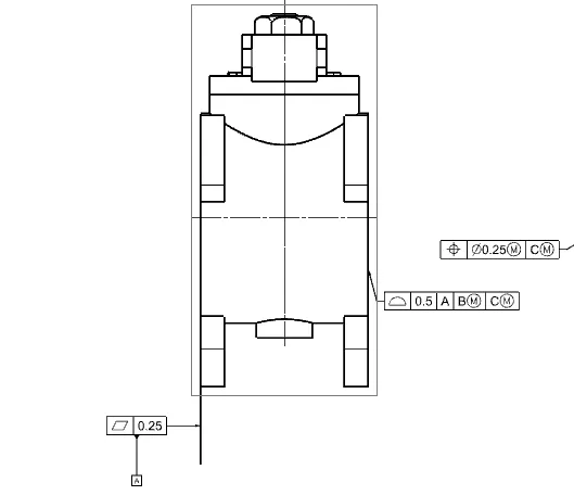
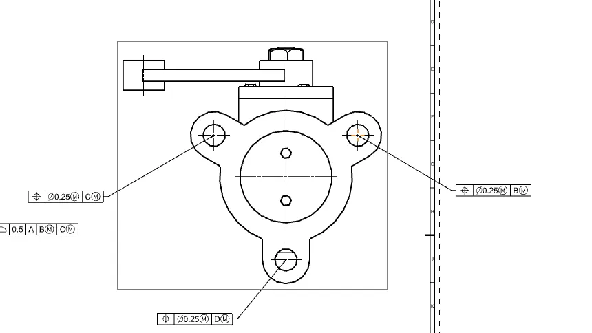
To apply the GD&T to this assembly, we need to apply it to the features which come in contact with the other parts and contribute to the positioning of the valve. In this case, all the required GD&T for individual parts have been applied already. Now it is applied to the assembly. Here, only the 3 holes on each side of the body come to contact with two pipes. So, the primary datum is defined as the surface containing 3 holes with the application of circular datum targets. Perpendicular tolerance and position tolerances are applied to the respective holes in order to define secondary and tertiary datum and also a sub-datum D in this case. As the holes on the other sides should be aligned with the holes on one side, position tolerance is applied to each hole with respect to the datum of the opposite holes. Flatness tolerance is applied to the primary datum whereas profile tolerance is applied to the other side of the body.