Week 10 - Challenge 1- Attachment Feature Creation (Ribs & Screw Boss)
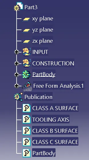
TREE STRUCTURE:
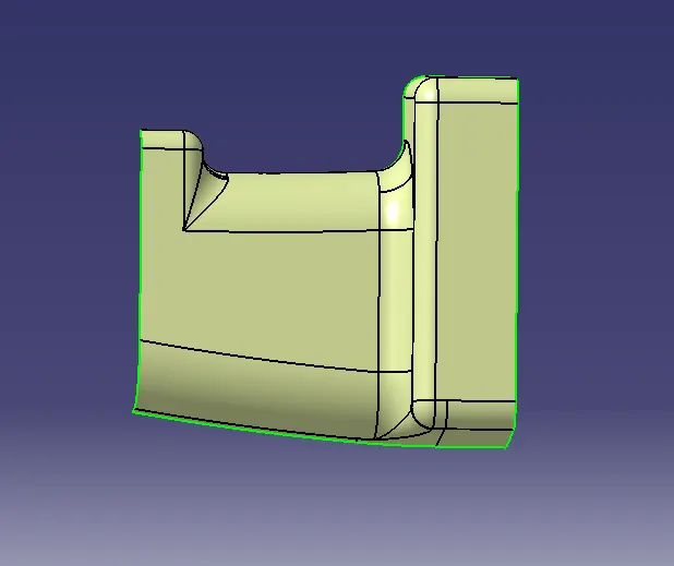
CLASS A SURFACE:
TOOLING AXIS:
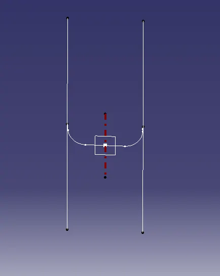
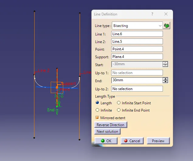
The first step is to observe the given class-A surface deeply and we can say the larger flat area which is perpendicular to the Tooling axis. So, by considering this thing for this class-A surface tooling direction will be in the X-direction. so we create the point on the flat surface as shown in the figure.
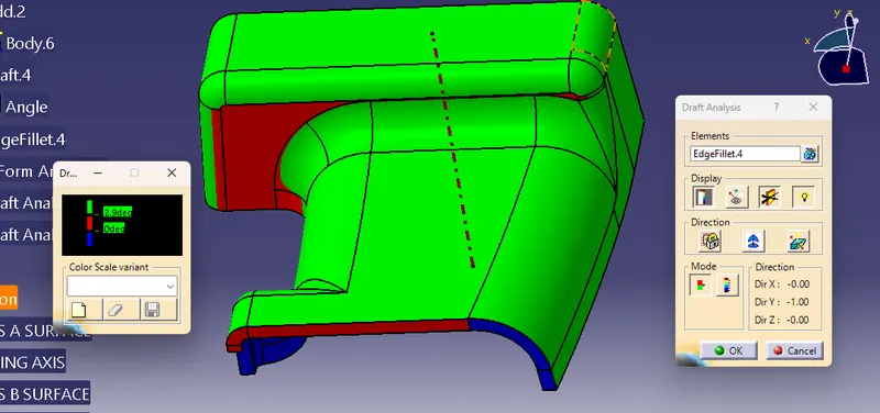
DRAFT ANAYSIS( CLASS A SURFACE):
The Draft Analysis is a command enables you to detect if the part you drafted will be easily removed. This type of analysis is performed based on colour ranges identifying zones on the analysed element where the deviation from the draft direction at any point, corresponds to specified values.
Draft analysis is done after determining the tooling axis, draft analysis is used to check whether the minimum draft (3 degrees) is maintained or not.

CLASS B SURFACE CREATIONS:
The A-surface is offsetted by 3.00mm as it is the thickness required.The offset surface is the B-surface but had some issues like in some areas
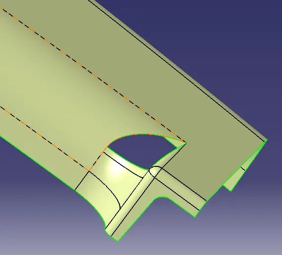
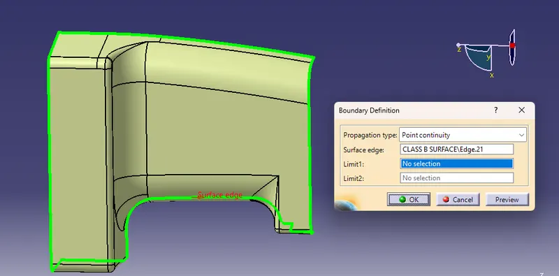
The Areas where the B-surface has issues are corrected by closing them using commands like Multi section,Sweep,Offset and extract.Finally all the created surfaces are trimmed or joined together with offset surfaces done earlier. This created a single single surface which will act as the final B-surface.B surface created is checked for any gaps or errors by creating a complete boundary.
CLASS C SURFACE CREATIONS:
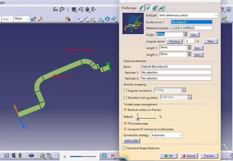
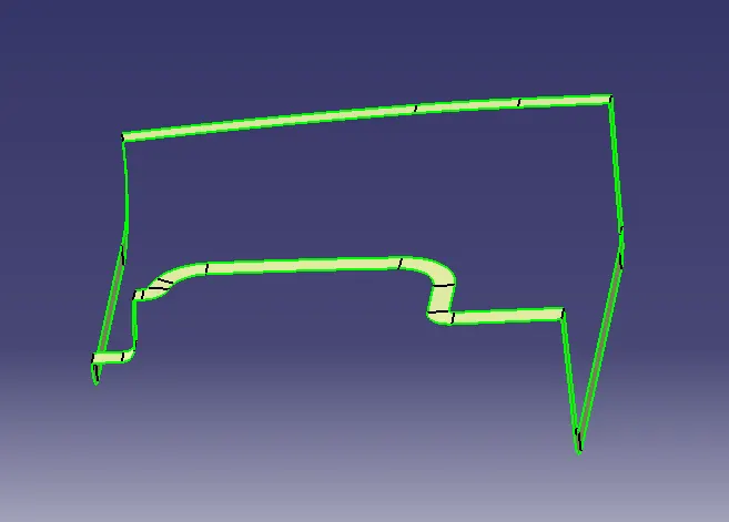
The A and B surfaces are connected by another single surface which is called the C surface.It is created by using sweep with A surface acting as the reference surface and curve created from the boundary of the same surface.Sweep with draft direction is also used to create A-surfaces.Since it is a complex class-A surface, we cannot simply create the class-A boundary curve and sweep it at one shot. Hence, we need to create smaller curves using multi-extract command and then create sweep of 90 degree with reference to the surface option.
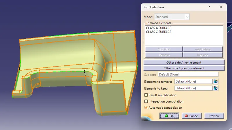
after that joining the class a surface and class c surface using trim options.
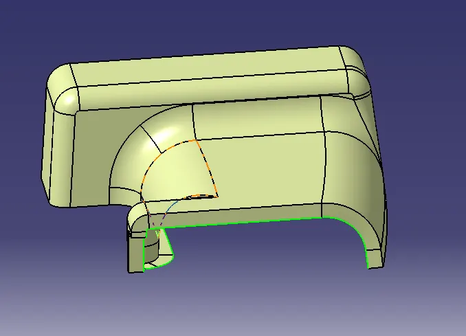
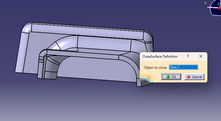
next to final body to get in the b surface body and above trim to used to apply the trim option command now get final output of the surface body.
CREATIONS OF ENGINEERING FEATURES:
RIB:
Rib provides an economical way to increase stiffness and strength to the mould parts without increasing the overall thickness of the wall. It is thin protrusion that extended perpendicular from the wall.
Rib root thickness analysis:
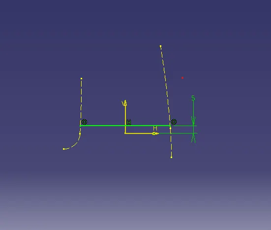
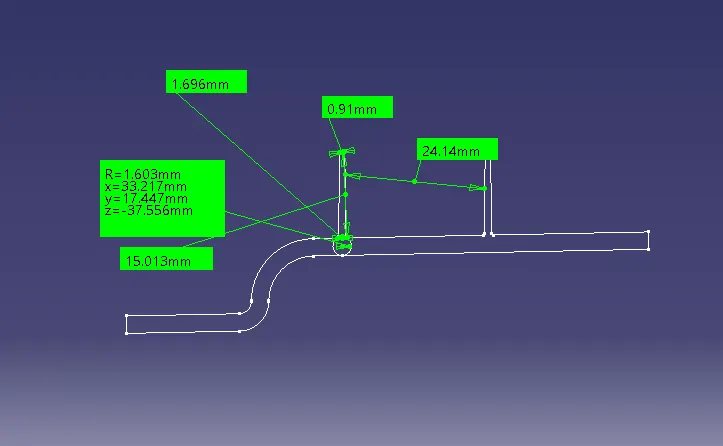
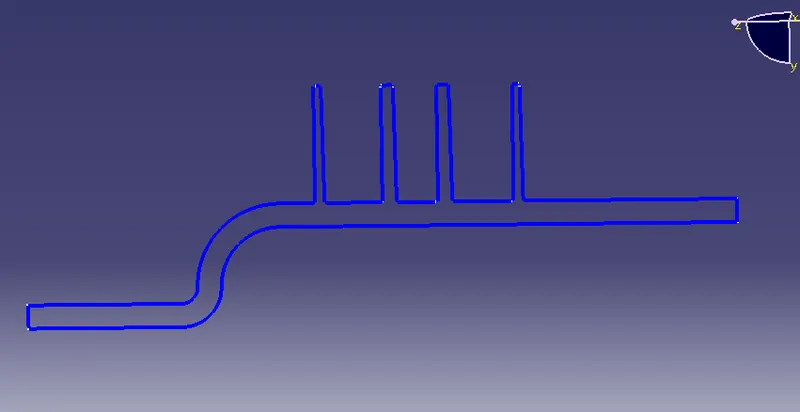
To check the Rib root thickness, first take perpendicular intersection across the body and the Rib and then have to sketch a circle which tangent to the Rib base or root area by using tritangent type circle. The value must be within 30% greater of the wall thickness.
SCREW BOSS:
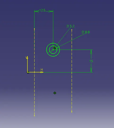
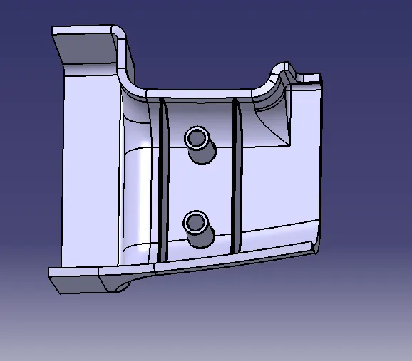
Screw boss are used as a point for attachment and assembly, most common in as cylindrical projection with hole design to receive screw or other types of fastening hardware.
FINAL DRAFT ANALYSIS