Week 14 challenge
AIM : The objective of this project is to design a butterfly valve and apply GD&T to it's components and final assembly using Siemens NX.
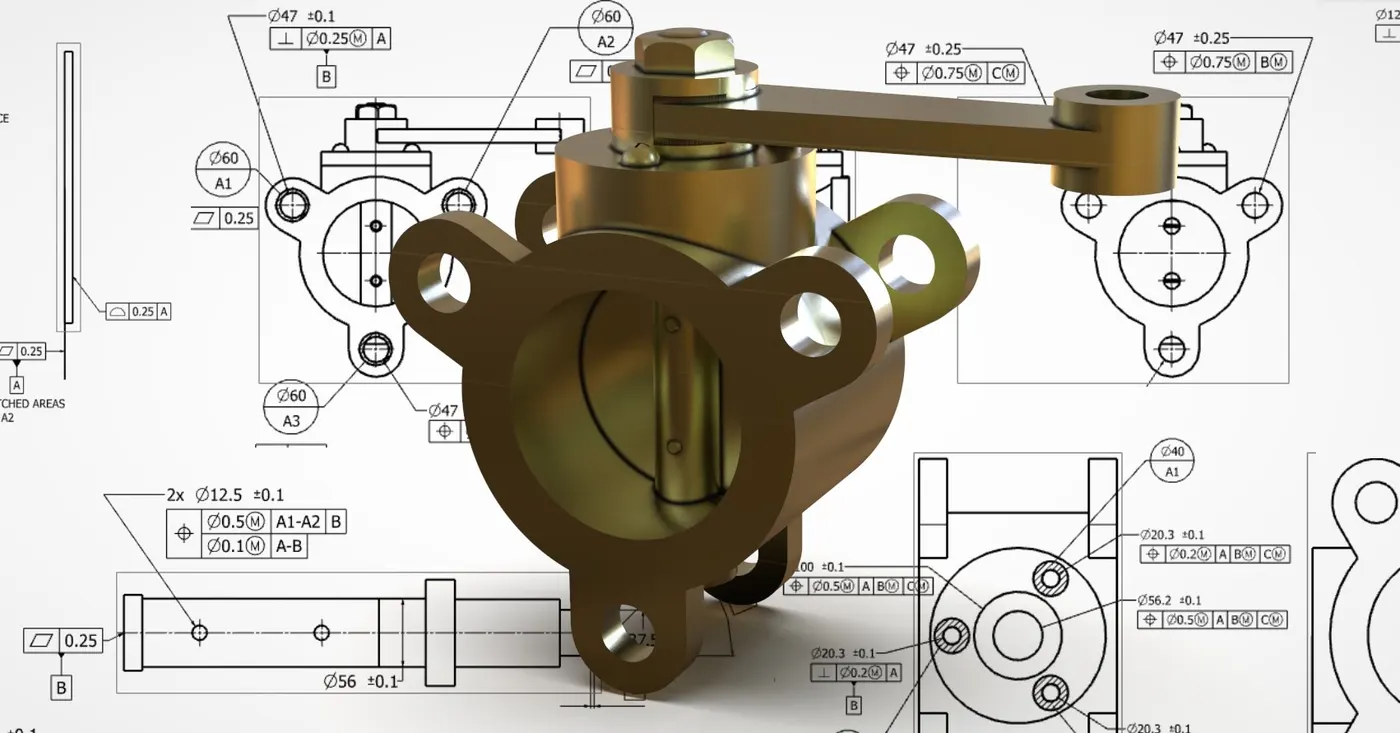
INTRODUCTION
A butterfly valve is from a family of valves called quarter-turn valves. In operation, the valve is fully open or closed when the disc is rotated a quarter turn. The "butterfly" is a metal disc mounted on a shaft. When the valve is closed, the disc is turned so that it completely blocks off the passageway.When the valve is fully open, the disc is rotated a quarter turn so that it allows an almost unrestricted passage of the fluid. The valve may also be opened incrementally to throttle flow.There are different kinds of butterfly valves, each adapted for different pressures and different usage.
Here after modelling various components of the Butterfly valve, GD&T (Geometric Dimensioning & Tolerancing) is applied to each component and final assembly.Geometric Dimensioning and Tolerancing (GD&T) is a system for defining and communicating engineering tolerances. It uses a symbolic language on engineering drawings and computer-generated three-dimensional solid models that explicitly describe nominal geometry and its allowable variation. It tells the manufacturing staff and machines what degree of accuracy and precision is needed on each controlled feature of the part. GD&T is used to define the nominal (theoretically perfect) geometry of parts and assemblies, to define the allowable variation in form and possible size of individual features, and to define the allowable variation between features.
There are several standards available worldwide that describe the symbols and define the rules used in GD&T. One such standard is American Society of Mechanical Engineers (ASME) Y14.5. This article is based on that standard, but other standards, such as those from the International Organization for Standardization (ISO), may vary slightly. The Y14.5 standard has the advantage of providing a fairly complete set of standards for GD&T in one document. The ISO standards, in comparison, typically only address a single topic at a time.
Advantages of applying GD&T:
- Saving Money - GD&T enhances design accuracy by allowing for appropriate tolerances that maximize production. For many projects, the process provides extra or bonus tolerances, further increasing cost effectiveness.
- Offering Uniformity and Convenience - As a single, consistent language, GD&T reduces guesswork and interpretation while ensuring consistent geometries across design and manufacturing.
- Assisting Digital Design Methods — Clear, concise GD&T data is readily adaptable to digital design programs, including nearly universally used 2D and 3D CAD files.
- Ensuring Dimensional and Tolerance Requirements — By explicitly stating all design requirements, a thorough GD&T process guarantees accurate fulfillment of all dimensional and tolerance specifications.
- Providing Accurate Communication — Today’s intricate designs demand the most accurate and reliable communication. GD&T enables designers, manufacturers, and inspectors to communicate clearly with one other, saving time and making the process more efficient.
COMPONENTS OF BUTTERFLY VALVE
Various components of butterfly valve and GD&T applied to them are shown below.
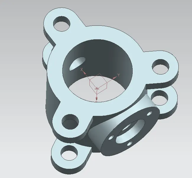
1. BODY - BUTTERFLY VALVE
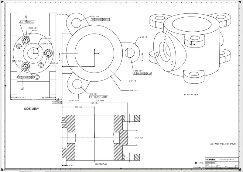
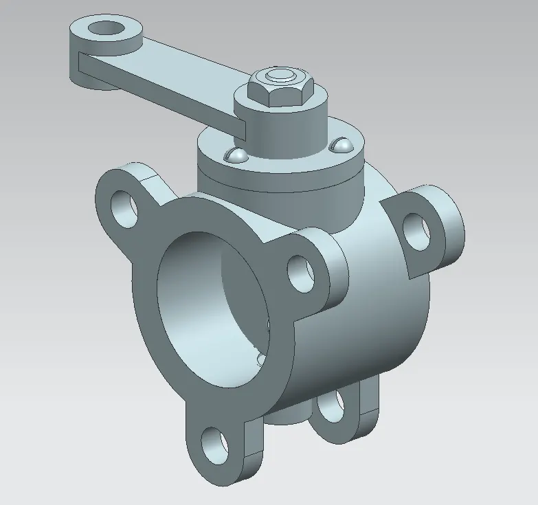
Butterfly valves are usually fixed between two pipleines using flange couplings. Body of our Butterfly valve and GD&T applied to the same using Siemens NX CAD are shown below.
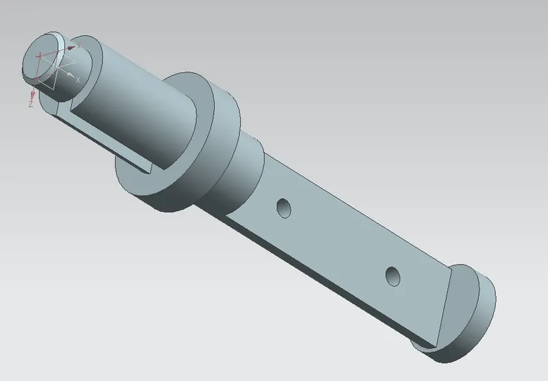
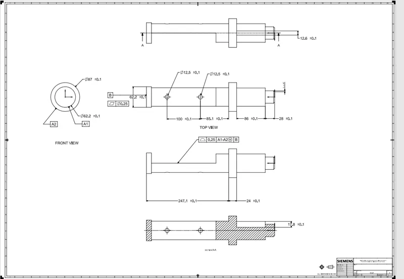
2. SHAFT - BUTTERFLY VALVE
The disc/plate, lever and nut are assembled to this shaft.
3. DISC - BUTTERFLY VALVE
When valve is fully opened or closed the disc is rotated a quarter turn.Disc is mounted on shaft. When the valve is closed, the disc is turned so that it completely blocks off the passageway.When the valve is fully open, the disc is rotated a quarter turn so that it allows an almost unrestricted passage of the fluid.
Your Answers
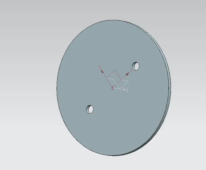
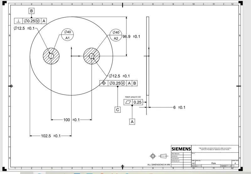
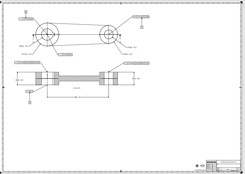
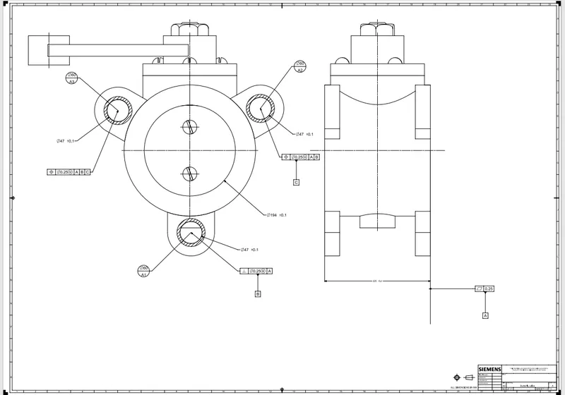
We can look in above 2D drawing sheet I have apply GD&T.
Firstly we have click on application button and click on drafting tool and selected the size of sheet. After that created the arc on select the full circle. Again selecting the arc from center diameter of 40mm. click on key button ctrl+T this command are used for move the object from center point to another center point of circle. Creating between 2 arc.
Applied the Datum target for 2 holes diameter of 40mm for Datum Target A1 & A2.
We can seen in above drawing created 2 Holes diameter of this holes are 12.5 mm and tolerance values + and – 0.1.
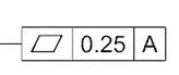
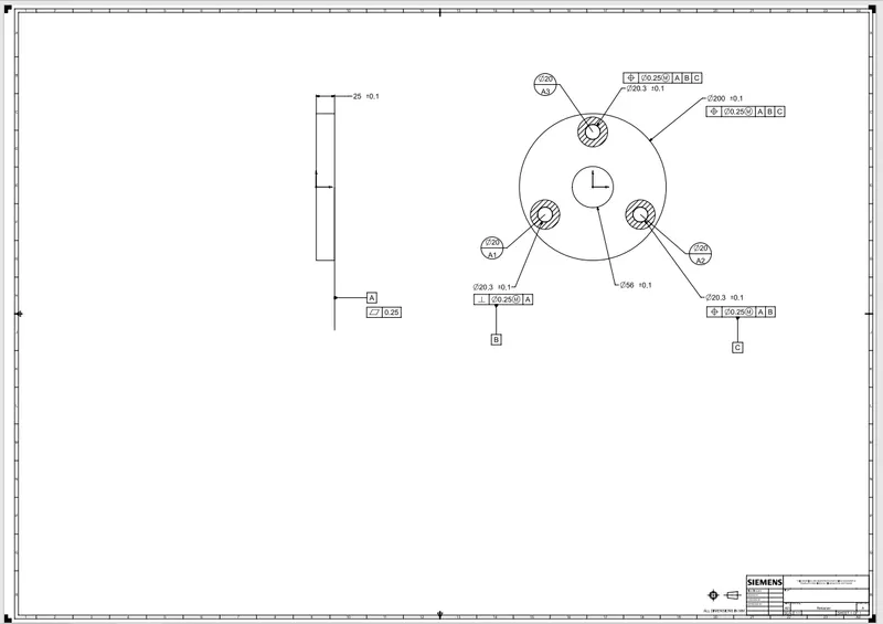
In above Feature Control Frame the tolerance symbol used Flatness of the tolerance value 0.25 related to the Datum Feature A.
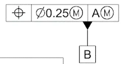
In above symbol the the position of the feature axis must be within a 0.25 tolerance zone at MMC relative to the Datum Feature A at MMC.
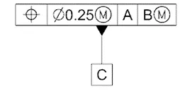
In above symbol the position of the feature axis must be within a 0.25 tolerance zone at MMC relative to the Datum Feature A and Datum Feature B at Maximum Material Condition (MMC).
4. LEVER - BUTTERFLY VALVE
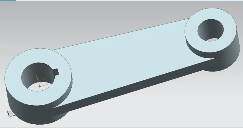
Lever is mounted at an end of shaft outside the body. Hand lever is usually used in small sized Butterfly valves. It is used to open or close the valve.
5. RETAINER - BUTTERFLY VALVE
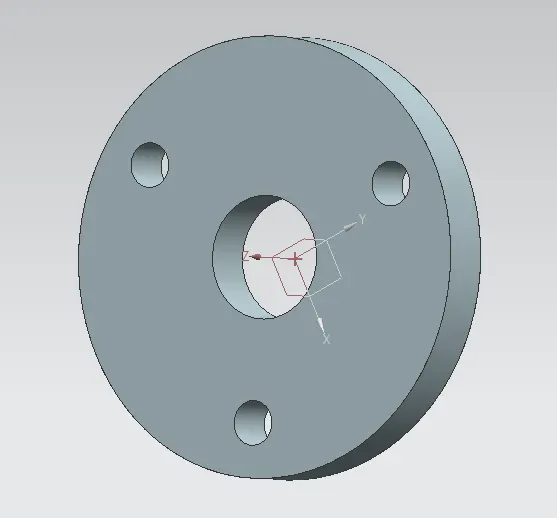
Retainer is a kind of washer fixed on the body of butterfly valve.
6. NUT - BUTTERFLY VALVE
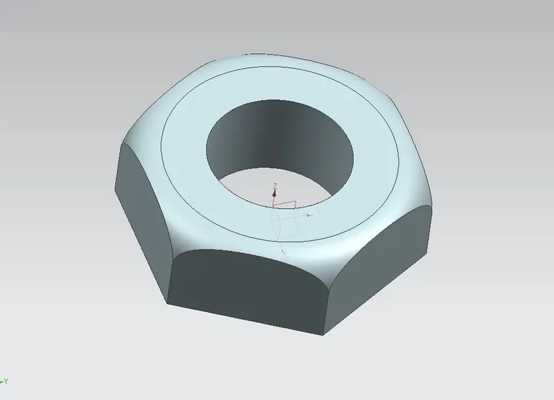
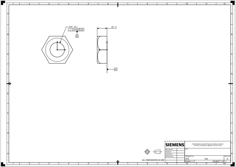
It is fixed at the top end of shaft to keep the lever and retainer on position relative to the body of butterfly valve.
ASSEMBLY - BUTTERFLY VALVE
After completing the modelling of various components of butterfly valve, all parts were assembled together using Siemens NX Assembly workbench.
CONCLUSION
Butterfly valve was successfully designed and GD&T applied to all parts and the assembly of the Butterfly valve.