Week 14 challenge
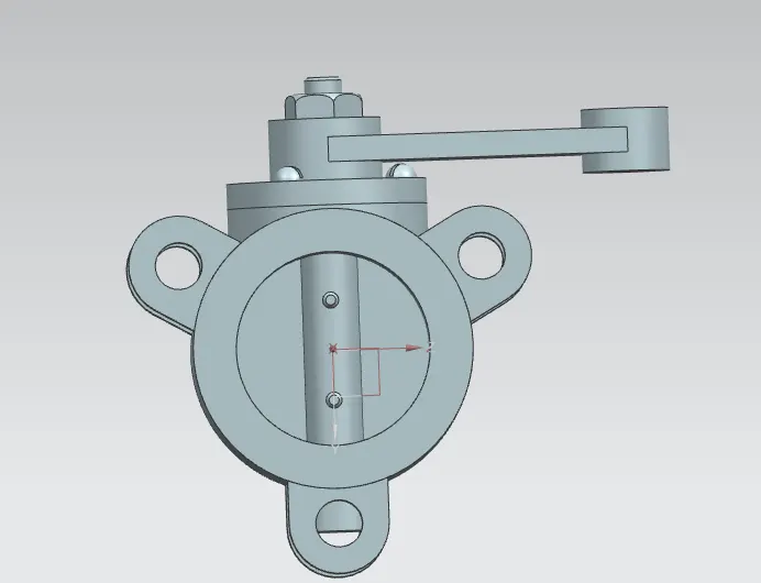
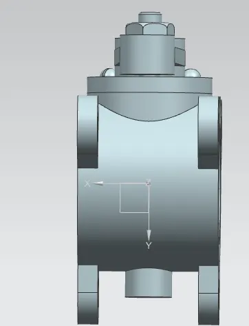
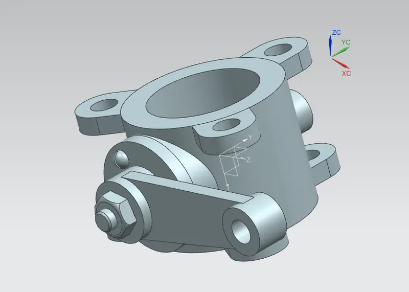
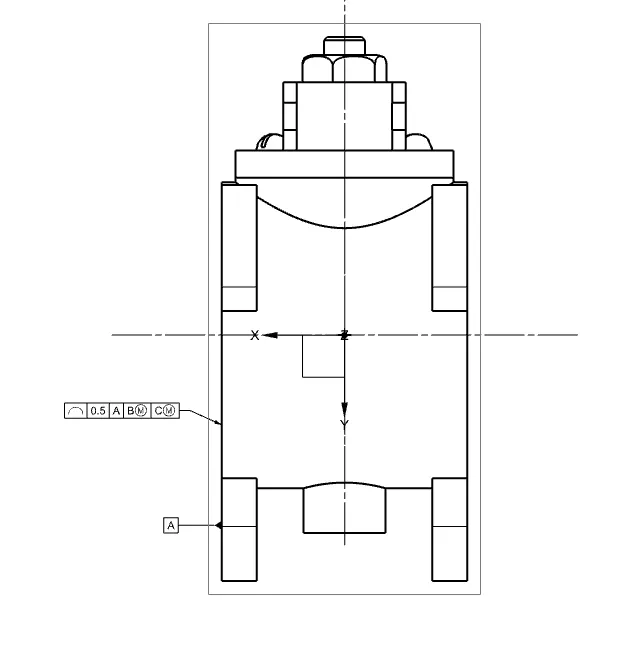
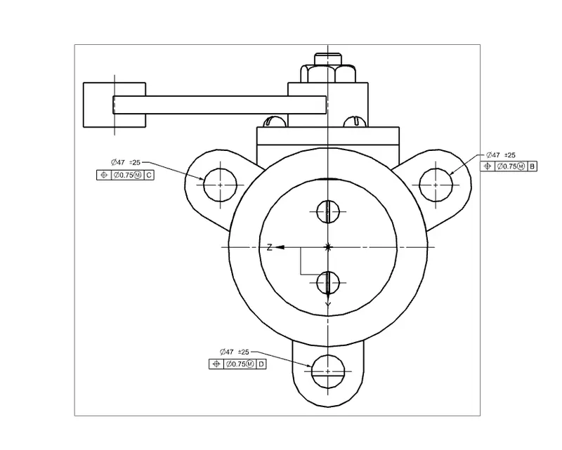
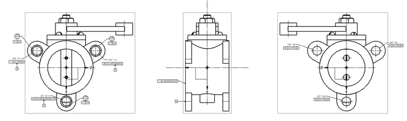
Assemble and apply GD&T to the butterfly valve assembly drawing.
REPORTS :
Introduction: Geometric Dimensioning and Tolerancing (GD&T) is a set of standardized symbols and practices used to communicate engineering tolerances and dimensions on technical drawings. In this report, we will discuss the process of assembling a butterfly valve and applying GD&T to its assembly drawing to ensure accurate manufacturing and efficient functionality.
1. Butterfly Valve Assembly: The butterfly valve is a common type of quarter-turn valve used to regulate or isolate the flow of fluid through a pipe. It consists of a circular disc, known as the "butterfly," mounted on a rod or shaft within a pipe. When the valve is in a closed position, the disc blocks the flow, and when it's in an open position, the disc allows fluid to pass through the pipe.
2. Assembling the Butterfly Valve: The assembly process of a butterfly valve involves the following steps:
a. Preparation: Gather all the required components, such as the valve body, disc, stem, actuator, gaskets, and fasteners.
b. Valve Body and Disc Alignment: Align the butterfly disc with the valve body's centerline, ensuring proper orientation and smooth rotation.
c. Securing the Disc to the Stem: Connect the disc to the stem securely, enabling the actuator to control its movement effectively.
d. Installing the Actuator: Attach the actuator to the valve assembly, which will provide the necessary force to open or close the butterfly disc.
e. Gasket Placement: Position the gaskets carefully to create a leak-tight seal between the valve body and the connected pipes.
f. Fastening and Torquing: Fasten all the components using appropriate torque values to prevent any looseness or damage during operation.
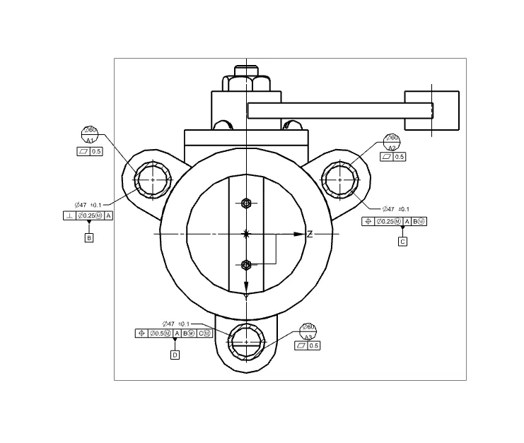
3. Geometric Dimensioning and Tolerancing (GD&T) for Butterfly Valve Assembly Drawing: GD&T is essential for accurately defining the dimensional requirements and tolerances of various components in the butterfly valve assembly. It helps to ensure interchangeability, functionality, and manufacturability. Here are some key GD&T symbols and practices used in the butterfly valve assembly drawing:
a. Tolerance Zones: GD&T defines tolerance zones around critical features, such as the centerline of the stem, the concentricity of the disc with respect to the valve body, and the perpendicularity of the actuator mounting surface.
b. Datum Reference Frame (DRF): A DRF is established to provide a reference for the measurements and tolerances. It helps ensure consistent measurement and assembly.
c. Position Tolerance: The position tolerance is used to control the location of features, such as the stem centerline and the actuator mounting holes, with respect to the datum reference frame.
d. Circularity: This symbol specifies the roundness of the butterfly disc and ensures smooth rotation within the valve body.
e. Flatness: The flatness tolerance may apply to the mounting surface of the valve body and the actuator to ensure proper contact and alignment.
Conclusion: Applying GD&T to the butterfly valve assembly drawing enhances the clarity of the design intent, improves manufacturing precision, and guarantees the proper functionality of the valve. By following the assembly process and adhering to GD&T principles, manufacturers can produce high-quality butterfly valves that meet engineering specifications and perform reliably in various applications.
( I HAVE MADE SOME MISTAKES IN THE ORIENTATION )