Week 14 challenge
BUTTERFLY VALVE ASSEMBLY
Objective:
- Assemble and apply Geometric Dimensioning and Tolerancing (GD&T or GD and T) to the butterfly valve assembly drawing
- To create the 3D part of the butterfly valve parts like, Main Body, Shaft, Lever, Nut , Screw, Disc Plate etc.
- To apply Geometric Dimensioning and Tolerancing (GD&T or GD and T) to the butterfly valve assembly drawing.
- To understand the concept of Geometric Dimensioning and Tolerancing (GD&T or GD and T)
Butterfly Valve:
A Butterfly valve is a quarter-turn rotational motion valve, that is used to stop, regulate, and start flow. Butterfly valves are easy and fast to open. A 90° rotation of the handle provides a complete closure or opening of the valve. Large Butterfly valves are usually equipped with a so-called gearbox, where the handwheel by gears is connected to the stem. This simplifies the operation of the valve, but at the expense of speed.
Butterfly valves are especially well-suited for the handling of large flows of liquids or gases at relatively low pressures and for the handling of slurries or liquids with large amounts of suspended solids. Butterfly valves are built on the principle of a pipe damper. The flow control element is a disk of approximately the same diameter as the inside diameter of the adjoining pipe, which rotates on either a vertical or horizontal axis. When the disk lies parallel to the piping run, the valve is fully opened. When the disk approaches the perpendicular position, the valve is shut. Intermediate positions, for throttling purposes, can be secured in place by handle-locking devices.
Advantages of Butterfly valve:
- Compact design requires considerably less space, compared to other valves
- Light in weight
- Quick operation requires less time to open or close
- Available in very large sizes
- Low-pressure drop and high-pressure recovery
Disadvantages of Butterfly valve:
- Throttling service is limited to low differential pressure
- Cavitation and choked flow are two potential concerns
Geometric Dimensioning and Tolerancing (GD&T or GD and T):
According to the ASME Y14.5-2009 standard, the purpose of GD&T is to describe the engineering intent of parts and assemblies. The datum reference frame can describe how the part fits or functions. GD&T can more accurately define the dimensional requirements for a part, allowing over 50% more tolerance zone than coordinate (or linear) dimensioning in some cases. Proper application of GD&T will ensure that the part defined on the drawing has the desired form, fit (within limits) and function with the largest possible tolerances. GD&T can add quality and reduce cost at the same time through producibility.
GD&T, short for Geometric Dimensioning and Tolerancing, is a system for defining and communicating design intent and engineering tolerances that helps engineers and manufacturers optimally control variations in manufacturing processes.
GD&T, a vital part of complex machining, offers a number of major advantages: Saving Money GD&T enhances design accuracy by allowing for appropriate tolerances that maximize production. For many projects, the process provides extra or bonus tolerances, further increasing cost effectiveness.
Parts of Butterfly Valves:
- Main Body of Butterfly Valve
- Shaft
- Retainer
- Disc Plate
- Nut
- Screw
Components of Butterfly Valve:
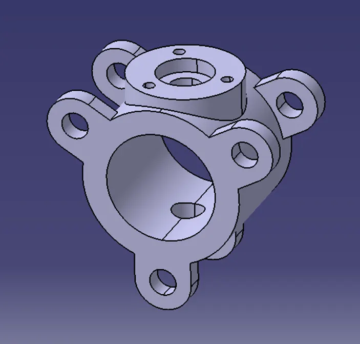
Body:
Butterfly valves generally have bodies that fit between two pipe flanges. The most common body designs are lug and wafer.
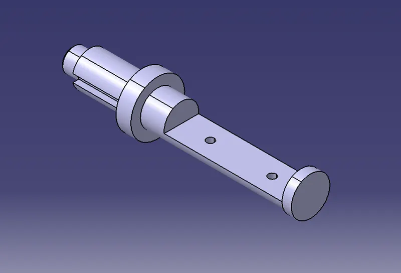
Stem/Shaft:
The stem of the butterfly valve may be a one-piece shaft or a two-piece (split-stem) design.
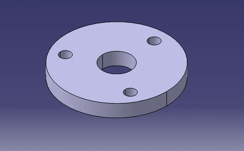
Retainer:
The retainer is a specially shaped washer that fits over the top of the valve spring. The keepers, or locks, fit into the valve stem grooves, holding the retainer and spring in place.
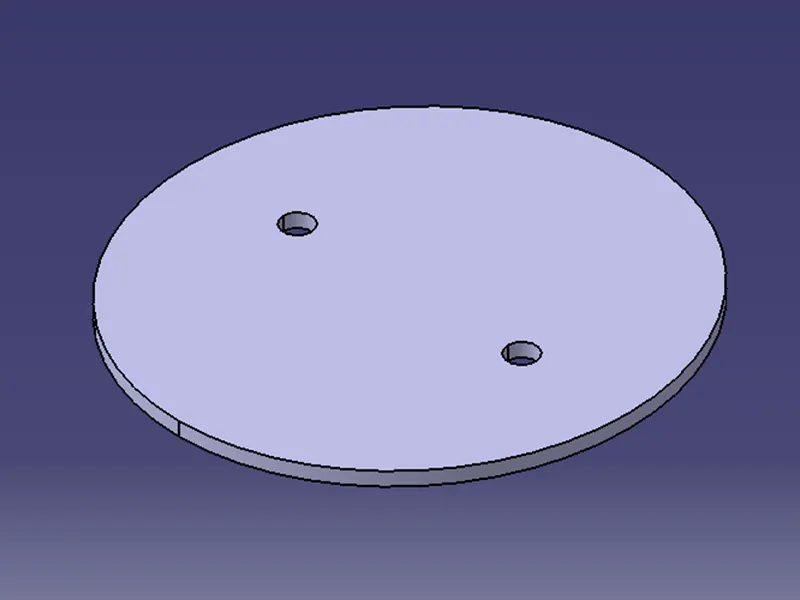
Disc Plate:
The flow closure member of a butterfly valve is the disk. The disk is the equivalent of a plug in a plug valve, gate in a gate valve or a ball in a ball valve. Rotating the disk one-quarter turn or 90 Degrees opens and closes the butterfly valve.
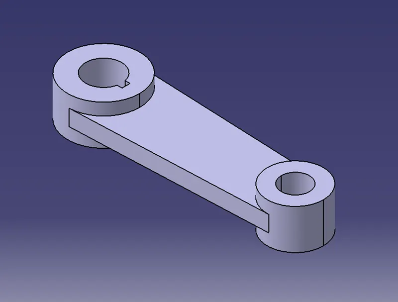
Lever:
The hand lever is commonly used for small butterfly valves and is used to open and closed the valve. It is capable of being locked into a position of open, partially open, or closed.
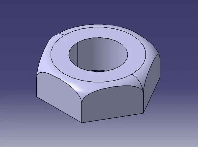
Nut:
Nuts are almost always used in conjunction with a mating bolt to fasten multiple parts together. The two partners are kept together by a combination of their threads' friction.
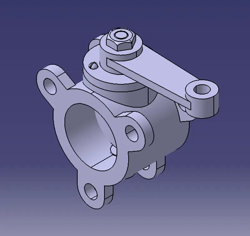
Assembly:
After modelling all the individual parts of the butterfly valve, all parts are assembled together in the assembly workbench of catia V5.
Assembly Drawing:
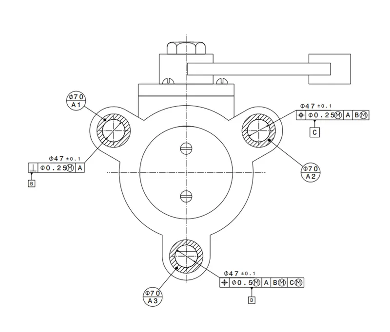
In the above shown lug type butterfly valve area A1, A2, A3 is considered as datum A and flatness 0.25mm applied on the datum A.
“A Perpedicularity tolerance of 0.25mm to be applied in a circular tolerance zone for the feature Ø47 at MMC with respect to datum A. it is considered as datum B.”
“A Position tolerance of 0.25mm to be applied in a circular tolerance zone for the feature Ø47 at MMC with respect to datum A and MMB with respect to B. it is considered as datum |C.”
“A Position tolerance of 0.5mm to be applied in a circular tolerance zone for the feature Ø47 at MMC with respect to datum A and MMB with respect to B & C. it is considered as datum D.”
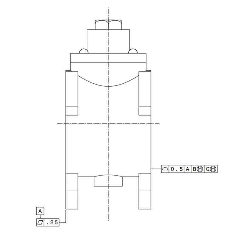
The opposite surface has profile tolerance 0.5mm to be applied on the marked surface. This surface must lie between two similar profiles spaces 0.5mm apart at MMC with respect to datum A and MMB with respect to B & C.
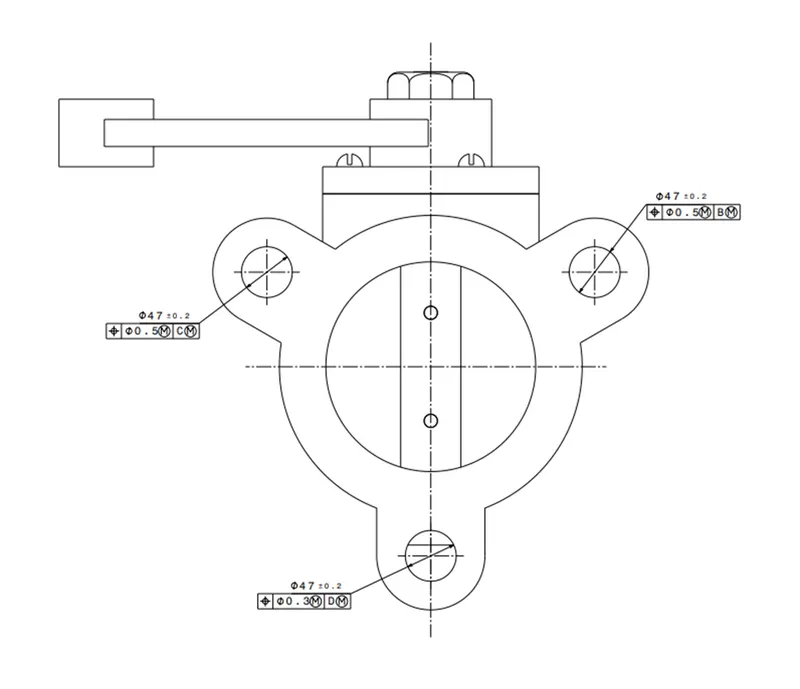
“A Position tolerance of 0.5mm to be applied in a circular tolerance zone for the feature Ø47 at MMC with respect to datum C.”
“A Position tolerance of 0.5mm to be applied in a circular tolerance zone for the feature Ø47 at MMC with respect to datum B.”
“A Position tolerance of 0.3mm to be applied in a circular tolerance zone for the feature Ø47 at MMC with respect to datum D.”
Conclusion:
In this project, a butterfly valve designed and assembled in the catia V5 Software and applied GD&T on Assembly part. GD&T according to ASME Y14.5 is applied at every stage of the part design process is a system for defining and communicating design intent and engineering tolerances that helps engineers and manufacturers optimally control variations in manufacturing processes.