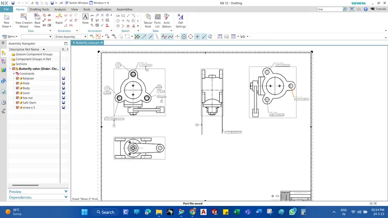
Week 14 challenge
Assemble and apply GD&T to the butterfly valve assembly drawing
Applications of Butterfly Valves
A Butterfly valve can be used in many different fluid services and they perform well in slurry applications. The following are some typical applications of Butterfly valves:
Cooling water, air, gases, fire protection, etc.
Slurry and similar services
Vacuum service
High-pressure and high-temperature water and steam services
Advantages of Butterfly Valves
Compact design requires considerably less space, compared to other valves
Light in weight
Quick operation requires less time to open or close
Available in very large sizes
Low-pressure drop and high-pressure recovery
Disadvantages of Butterfly Valves
Throttling service is limited to low differential pressure
Cavitation and choked flow are two potential concerns
Disc movement is unguided and affected by flow turbulence
Parts of Butterfly Valves
- Butterfly valve body
- Shaft
- Disc Plate
- Lever
- Retainer
- Nut
- Bolt
Commands Used
- Line: This feature allows us to create a straight line. The line can be a solid line or a construction line.
- Circle: This feature allows us to create circles.
- Rectangle: This feature allows us to create squares or rectangles.
- Arc: This allows us to create an arc.
- Trim: This is used to trim sketches.
- Extrude Bose: This feature allows us to create solid bodies.
- Revolve: Revolves add or remove material by revolving one or more profiles around a centreline. You can create revolved bosses/bases, revolved cuts, or revolved surfaces. The Axis of Revolution can be a 3d sketch.
- Circular Pattern: This allows us to create a pattern in a circle
- Fillet: This is used to create circular edges.
- Hole: A Hole feature is used to create holes in the model.
- Unite: Unite is used to convert two or more solid bodies into one solid body.
Design and Methodology
Components of Butterfly Valve
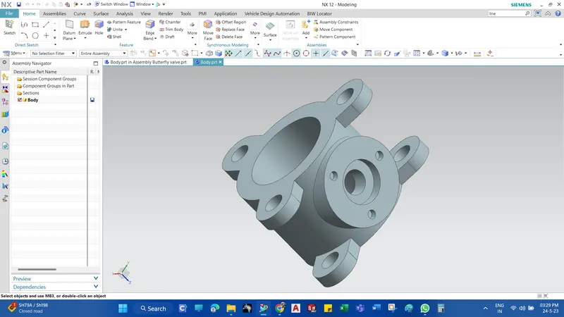
1. Butterfly valve body
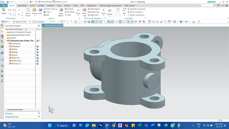
- Butterfly valves generally have bodies that fit between two pipe flanges. This butterfly valve has a lug body design consisting of protruding lugs that provide bolt holes matching those in the pipe flange.
- Create two circles of the required diameter and use Extrude command to form a cylindrical body/housing.
- On that cylindrical body create three lugs with holes in them. This will help us connect the butterfly valve to the pipe flanges. We have created the lugs on the mid-plane and then Extruded them with reference to the mid-plane(i.e. symmetrical value).
- Using the Move object command we created similar lugs on the outer surfaces of the body with the help of lugs created earlier.
2. Shaft
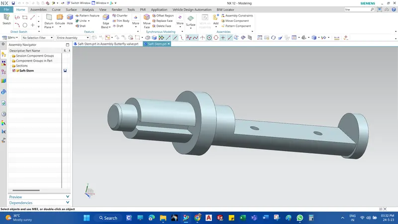
It is another important component of the butterfly valve. It inserts into the body of the valve and sits perpendicular to the direction of flow. It holds the disc inside the body and is clamped with the lever outside the body. It is created using simple features like revolve and extrudes features in the NX modeling environment. After the part creation is completed, the drawing is created in the drafting application of NX, and GD&T is applied using the features of NX. For this shaft, position tolerance should be given to the holes which hold the disc, a profile of the surface should be applied to the surface where the disc sits, and position tolerance for the cylindrical body of the shaft concerning the defined datums. Composite position tolerance is applied in the case of disc positioning holes as it repeats creating a pattern.
Features used to create Shaft :
- Sketch
- Revolve
- Datum plane
- Extrude
- chamfer
Initially, Select the XY coordinate and click on the line tool from the Sketch tab.
Revolve command is used to get the desired shape of the shaft.
Then Extrude command is used to create a recess portion in the front and rear portion of the shaft.
Finally, two holes of 12.5mm in diameter are created in the rear recess portion of the shaft.
Drafting
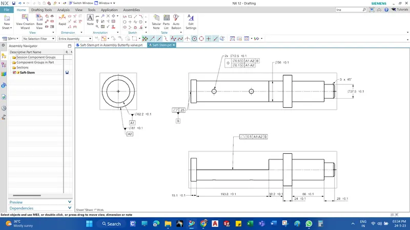
- A1 size of the sheet is used to create a drawing of the shaft.
- Here, only two datums are used as one degree of freedom is required for efficient working of the shaft.
- Datum A1 and A2 are given to the part which comes in contact with the body of the butterfly valve.
- Datum B is given to the base of the shaft.
- Different tolerances are given to some features which are important for the functioning of the shaft.
Disc Plate
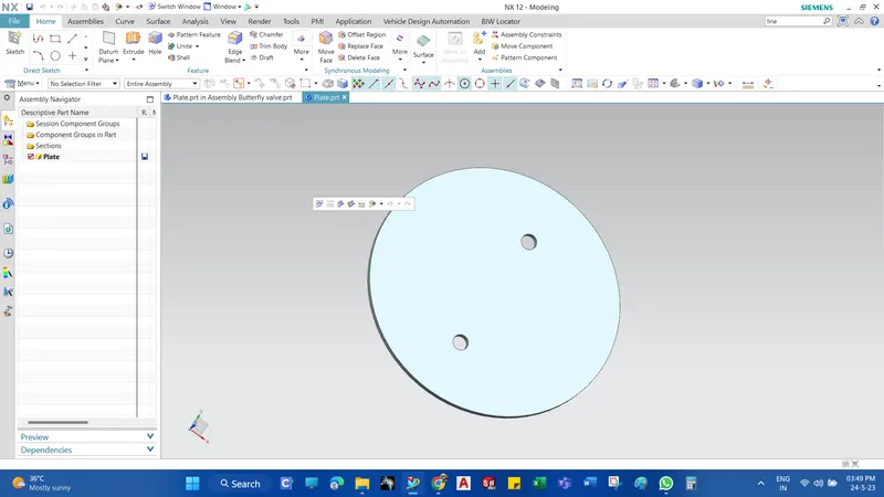
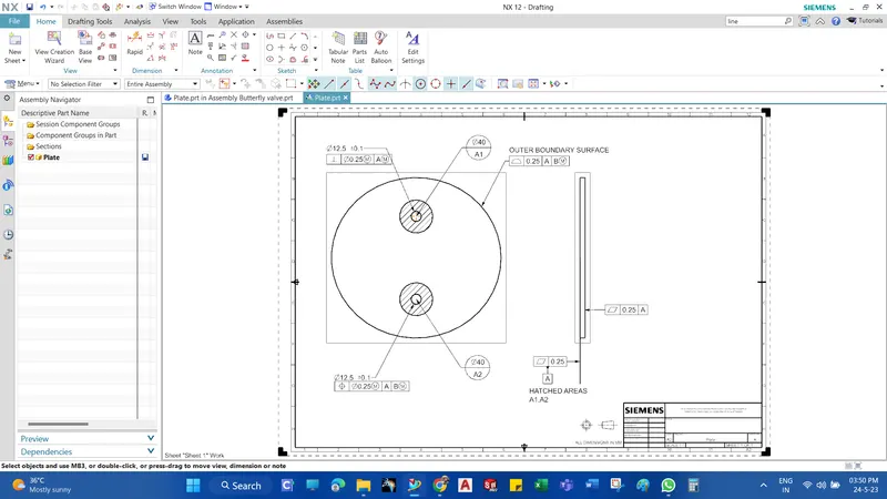
This disc plate is the main component of the butterfly valve which regulates the flow in the valve. The orientation of this disc determines the flow rate of the fluid. It is not perfectly circular, rather it is elliptical in profile. The holes in it help to position it properly on the shaft created earlier. A simple feature like extrude can create this part in NX. To apply GD&T for this part, the primary datum is defined on the surface where it comes in contact with the surface of the shaft, and perpendicular and perpendicular tolerances are applied as per the requirement. As the cost increases, while machining the entire contact surface, small circular datum targets are created and GD&T is applied to reduce the manufacturing cost.
Features used to create Disc plate :
- Sketch
- Extrude
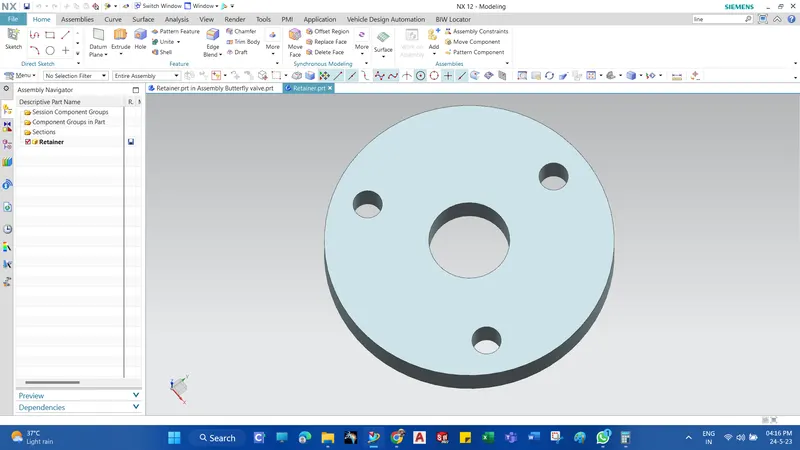
The 3D model of the Retainer is created with the help of given dimensions.
Initially, the concentric holes of 200mm and 56mm diameter are drawn and the other 3 circles of 20.3 mm diameter are drawn with the help of 150mmBCD by using the Pattern option.
Drafting
- After the modeling, the part is taken to the drafting portion where the three datums A, B, and C are applied.
- Datum target areas A1, A2, and A3(Primary datum-A) are applied to one side of the Retainer which comes in contact with the upper portion of the body.
- Datum-B is applied to one of the holes of the retainer where the bolt is inserted.
- Datum-C is applied to the other hole of the retainer.
- Finally, the other tolerances like Perpendicularity, position, and the profile of a surface are applied to the other holes and the surface of the retainer, the drawing is saved in the required folder.
Lever
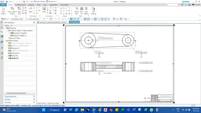
A lever is a handle that is used to rotate to regulate the flow. It is attached to the shaft with the help of a key to fix it in position concerning it. So when it is rotated, the shaft rotates which in turn rotates the disc and regulates the flow inside the pipe. It is created using simple features like extrude in NX after the proper base sketch is created. For the application of GD&T on the lever, a section view is also created to show how different datums are defined and tolerances are provided. Position tolerance is applied to the proper holes after the perpendicular tolerance is applied to the first hole. To control the key slot, small tolerance is applied to the width of it. Profile tolerances are provided to the surfaces which come to contact with other parts as per the requirement.
Features used to create Lever :
- Sketch
- Extrude
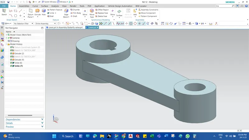
With the help of a 2D drawing of the lever, the 3D model of the lever is designed with the help of different operations.
2. The different operations used are Trim, Extrude, circle, Tangency, etc.
3. Finally, the part is saved in the required folder.
Retainer
This part helps to retain or to fix the shaft with the body of the butterfly valve. It prevents the shaft from coming out of the body and keeps it in position for the proper functioning of the disc inside the body. The creation of the retainer plate involves only a simple feature like extruding in NX. For the GD&T application in the retainer plate, similar steps are followed as in the case of the disc. Primary, secondary, and tertiary datums are defined properly as per the design intent, and datum targets are applied to the holes. Perpendicular and position tolerances are applied to lock the DOF of the retainer in position. A profile tolerance is also applied to control the upper surface of the retainer.
Features used to create Retainer :
- Sketch
- Extrude
The 3D model of the Retainer is created with the help of given dimensions.
Initially, the concentric holes of 200mm and 56mm diameter are drawn and the other 3 circles of 20.3 mm diameter are drawn with the help of 150mmBCD by using the Pattern option.
Finally, the 2D sketch is extruded and the part is saved in the required folder.
Drafting
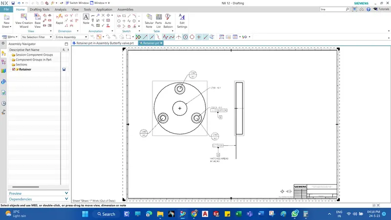
- After the modeling, the part is taken to the drafting portion where the three datums A, B, and C are applied.
- Datum target areas A1,A2,A3
- Primary datum-A is applied to one side of the Retainer which comes in contact with the upper portion of the body.
- Datum-B is applied to one of the holes of the retainer where the bolt is inserted.
- Datum-C is applied to the other hole of the retainer.
- Finally, the other tolerances like Perpendicularity, position, and the profile of a surface are applied to the other holes and the surface of the retainer, the drawing is saved in the required folder.
Nut
this is the final part that helps to fix the lever in position with the stem. It allows you to keep it in position or to disassemble it whenever required. It is created using simple extrude and revolve features in NX. To apply GD&T for this nut, the primary datum is defined on the surface which comes in contact with the lever. Perpendicular tolerance is applied to the hole or the thread and is defined as datum B. Size tolerance is also applied to the thickness of the nut.
Features used to create Nut :
- Sketch
- Extrude
- Revolve
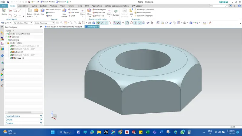
The 3D modeling of the Nut is created with the given dimensions.
Initially, the hexagonal-shaped nut is extruded with a depth of 25mm and a hole of 37mm diameter.
Finally, the fillet of radius 10mm is provided by using the revolve option.
Drafting
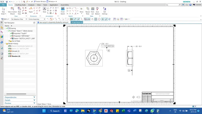
- Datum A is given to the bottom surface of Nut which is going to come in contact with the Lever surface.
- Datum B is given to the Hole.
- Finally, other tolerances are given to the surfaces and features of the Nut.
Assembly
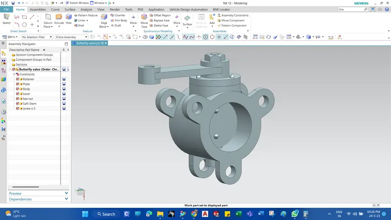
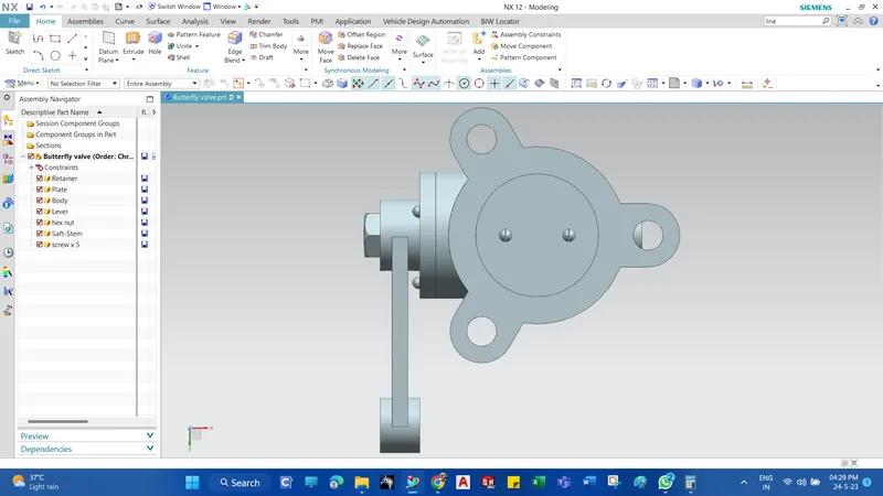
After the design, all the models should assemble with appropriate constraints. The assembly is created by first placing the body in position and mating other parts to it with the application of different joints provided in NX. First, the shaft and disc are joined together with the screws in place to create a sub-assembly which is then joined to the body in position. The retainer plate is then mated with the body and screws are used to fix them. After that, the lever is mated to the shaft in a position that is then fixed after the nut is mated with the shaft.
Features used to Assembly
- Infer Axis/center
- Touch Align
- Concentric
- Move Component
The Assembly file is opened in NX CAD.
The above parts are added to the assembly file.
Now, one by one part is assembled using the Move part command and assembly constraint command.
Different constraints are used to assemble the butterfly valves, such constraints are Infer Axis, Touch, and Align.
Finally, the assembly of the butterfly valve is saved in the folder where all the other parts are saved.

Drafting
- Datum target areas A1, A2, and A3 are given to the ears of the butterfly valve.
- Datum target areas A2 and A3 are given with perpendicular tolerance and Position tolerance respectively.
- Sub datum D is given to the third ear.
- Finally, other tolerances are given to the surfaces and features of the Butterfly Valve.