Week 14 challenge
AIM:
To design and Assemble components of Butterfly valve and apply GD&T to the assembly drawing.
OBJECTIVE:
- The objective is to design & assemble the components of the butterfly valve using various modeling & assembly features in SIEMENS NX CAD.
- Developing drawing sheets of butterfly valve assembly using various drafting tools.
- Understanding various GD&T symbols and applying the same to the butterfly valve assembly.
INTRODUCTION:
BUTTERFLY VALVE:
Butterfly valves are a family of quarter-turn rotational motion valves that are used in pipelines to shut-off flow. It is often said that butterfly valves can be used to regulate the flow. However, we do not recommend doing this, as it can damage the valve disk and have a negative effect on the sealing properties. They are used in a wide variety of process media and industries especially in water supply, collection, and distribution, as well as pumping stations, and have a broad range of use cases especially in flow isolation. A couple of their key advantages over other valve families are their simple construction and compactness, resulting in the end products being of lighter weights and lower cost and with smaller installation footprints and faster actuation speeds.
WORKING PRINCIBLE:
The construction of a butterfly valve is relatively simple, with the rotation of the valve disc controlling the fluid flow. In the closed position, the disc blocks the valve bore while in the open position, the disc is oriented perpendicular to the flow direction to allow flow. Butterfly valves generally provide bi-directional flow and shutoff capability. However, they are not full-bore, which renders them unsuitable for pigging or swabbing. The body material is ductile iron with an epoxy powder coat on both internal and external surfaces. The valves are typically operated by handwheels, gears, or actuators, or a combination thereof, according to the specific application requirement and technical specifications.
ADVANTAGES:
- Lightweight and Compact: With a compact design and a smaller face to face dimension, butterfly valves have a considerably less installation footprint and offer savings in the form of lower installation costs including labour cost, equipment, and piping support.
- Low Maintenance Requirements: An inherently simple, economic design that consists of few moving parts, and hence fewer wear points, significantly reduces their maintenance requirements.
- Fast Acting: A 90° rotation of the handle, or the actuation mechanism, provides a complete closure or opening of the valve. However, with larger butterfly valves, a gearbox is often required as part of the actuation mechanism which reduces the operational torque and simplifies the operation of the valve but comes at the expense of speed.
- Low Cost: Owing to their simple design, butterfly valves require less material and are simpler to design and manufacture and are often the more economical choice compared to other valve types. The cost savings are mainly realized in larger valve sizes, typically above DN 300.
- Versatility: Butterfly valves have a wide variety of use cases including the ability to be installed underground.
PROCEDURES
Developing Designs for the each component with proper given dimensions and assembled all the coponents in proper contraints.Once the components and assembly are developed, GD&t(geometric dimensioning and tolerancing) is applied to each component as well as the assembly. The purpose of GD&T is to describe the engineering intent of parts and assemblies. GD&T can more accurately define the dimensional requirements for a part, allowing over 50% more tolerance zone than coordinate (or linear) dimensioning in some cases. Proper application of GD&T will ensure that the part defined on the drawing has the desired form, fit (within limits), and function with the largest possible tolerances. GD&T can add quality and reduce cost at the same time through producibility.
There are several standards available worldwide that describe the symbols and define the rules used in GD&T. One such standard is the American Society of Mechanical Engineers (ASME) Y14.5. This article is based on that standard, but other standards, such as those from the International Organization for Standardization (ISO), may vary slightly. The Y14.5 standard has the advantage of providing a fairly complete set of standards for GD&T in one document. The ISO standards, in comparison, typically only address a single topic at a time.
COMPONENTS DESINGS.
Valve Body
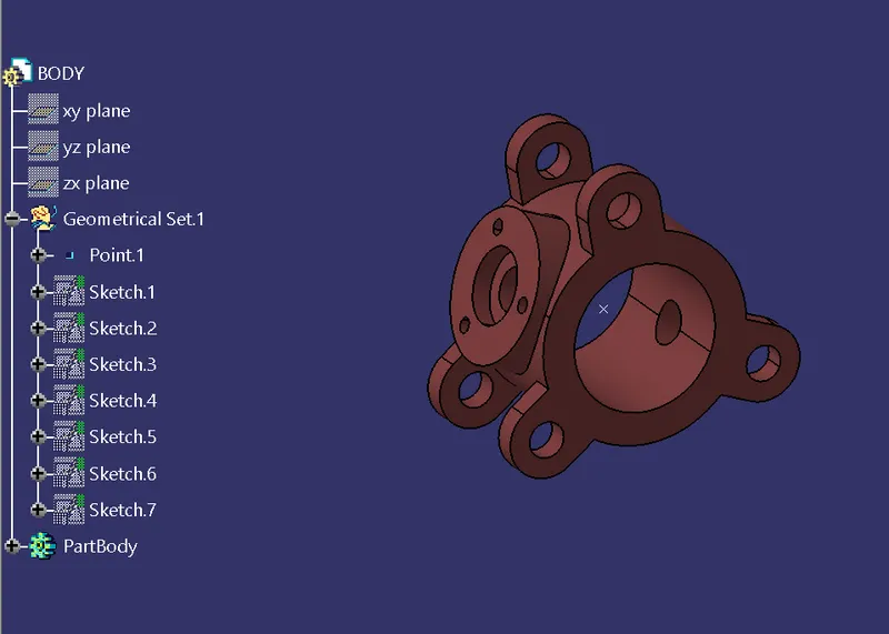
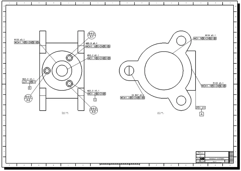
Butterfly valves generally have bodies that fit between two pipe flanges. The most common body designs are lug and wafer. The lug body has protruding lugs that provide bolt holes matching those in the pipe flange. A wafer body does not have protruding lugs. The wafer valve is sandwiched between the pipe flanges, and the flange bolts surround the body.
Designed component of body
Drawing
SHAFT
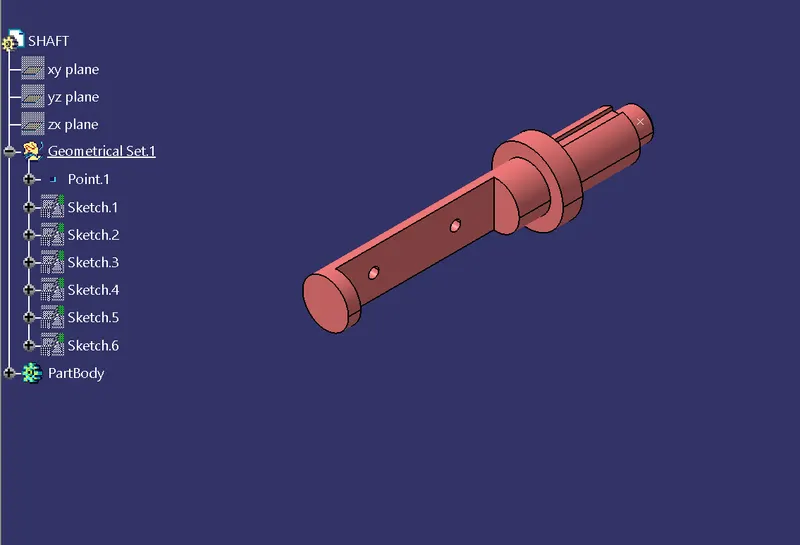
The stem of the butterfly valve may be a one-piece shaft or a two-piece (split-stem) design.
The stem in most resilient seated designs is protected from the media, thus allowing an efficient selection of material with respect to cost and mechanical properties.
In high-performance designs, the stems are in contact with the media and, therefore, must be compatible, as well as provide the required strength for seating and unseating the disk from the seat.
Designed component of Shaft
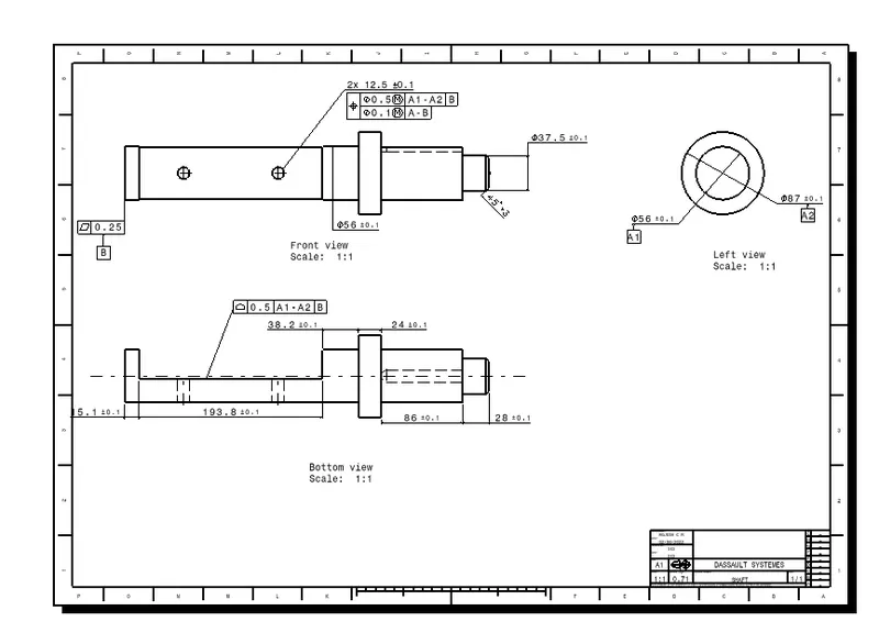
Drawing of Shaft
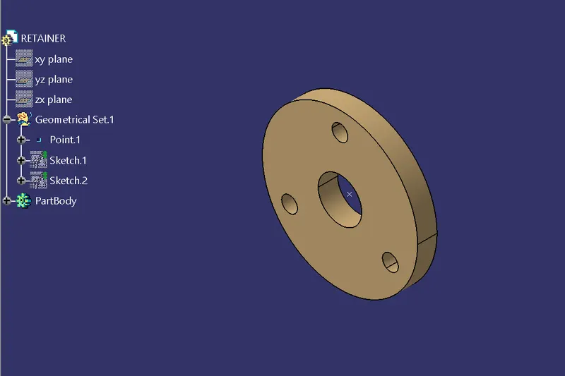
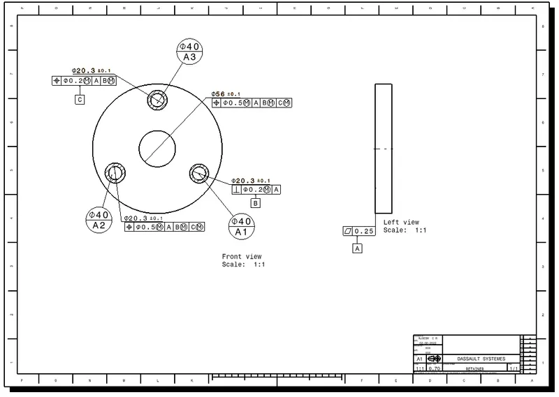
RETAINER:
It is some kind of washer assembled on the body of the butterfly valve and used to more fitment.
Designed component of Retainer
Drawing of Retainer
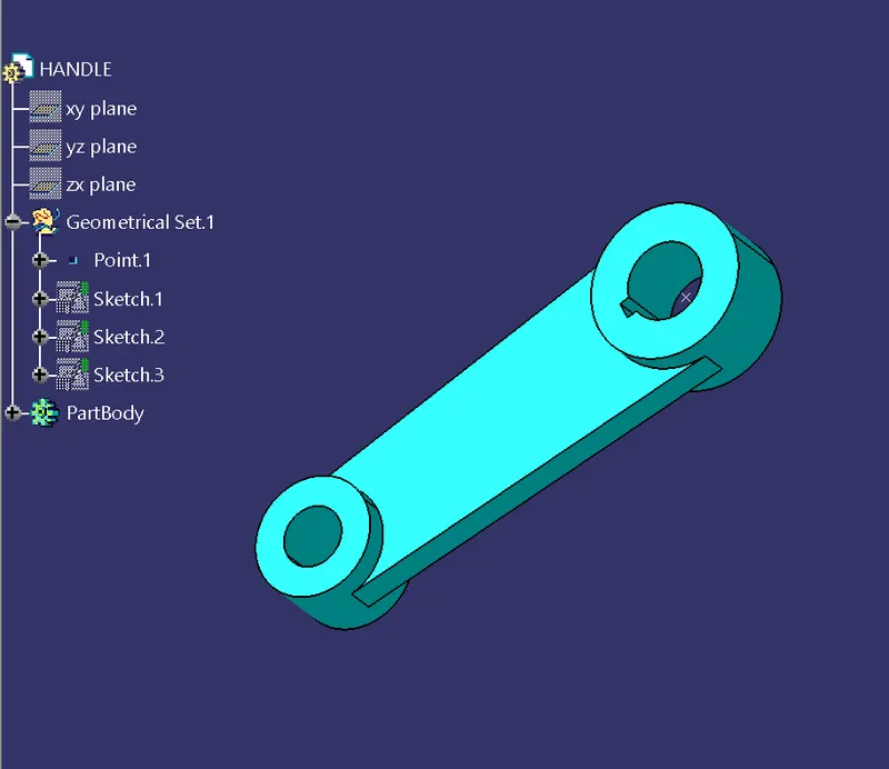
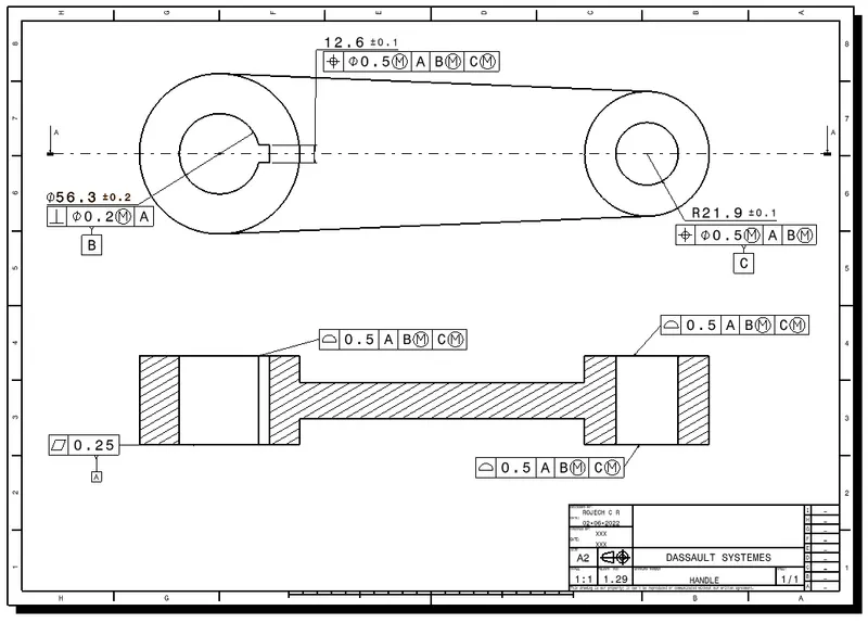
HANDLE:
The lever is attached at the end of the shaft/stem above the body & retainer. This lever handle is used in a small-sized butterfly valve. Using this we can regulate the flow by opening and closing the disc whenever required.
Designed component of Handle
Drawing of Handle
Disc plate
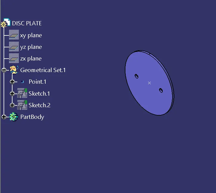
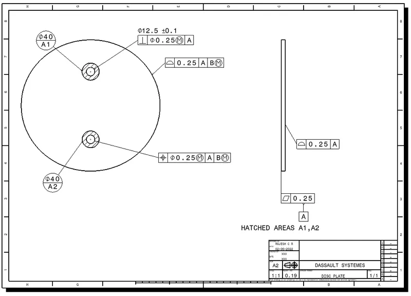
Attached to the valve body is the disc that functions as a gate that stops or throttles fluid flow; it can be considered equivalent to a gate in a gate valve, or a ball in a ball valve. The disc is typically bored to receive the stem, or shaft. There are many variations in disc design, orientation, and material in order to improve flow, sealing, and/or operating torque.
Designed component of Disc Plate
Drawing of Disc Plate:
NUT:
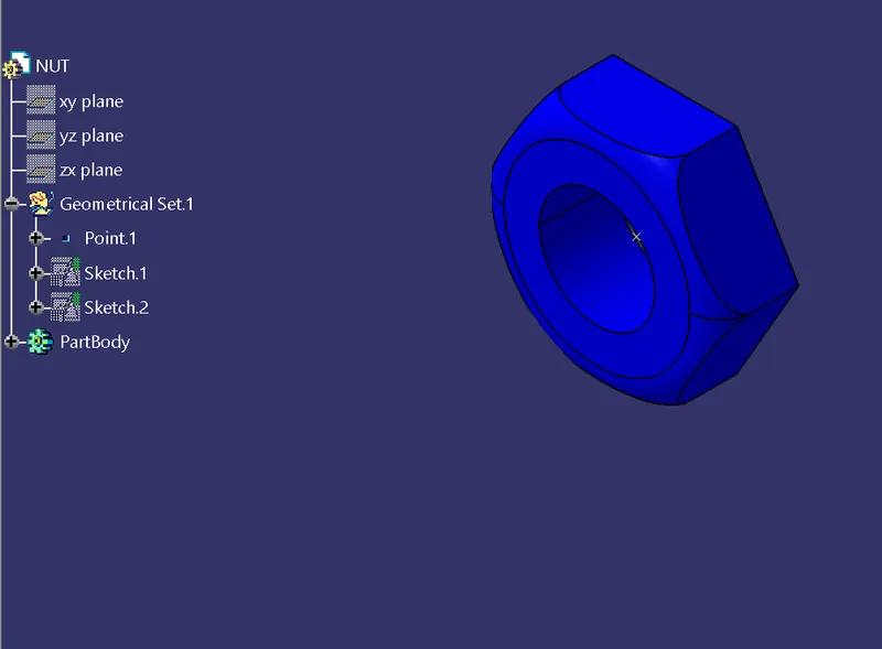
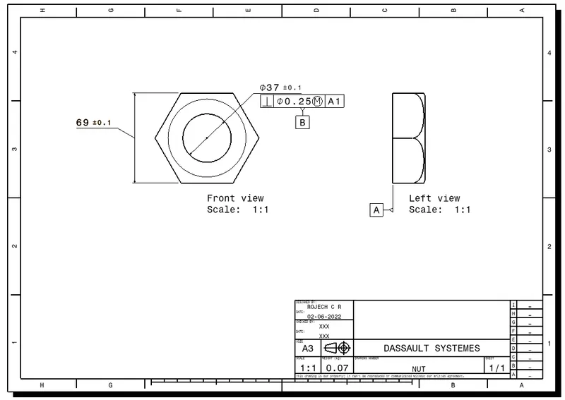
It is used to keep the lever and retainer intact with each other as well as the body of the butterfly valve.
Designed component of Nut
Drawing of Nut:
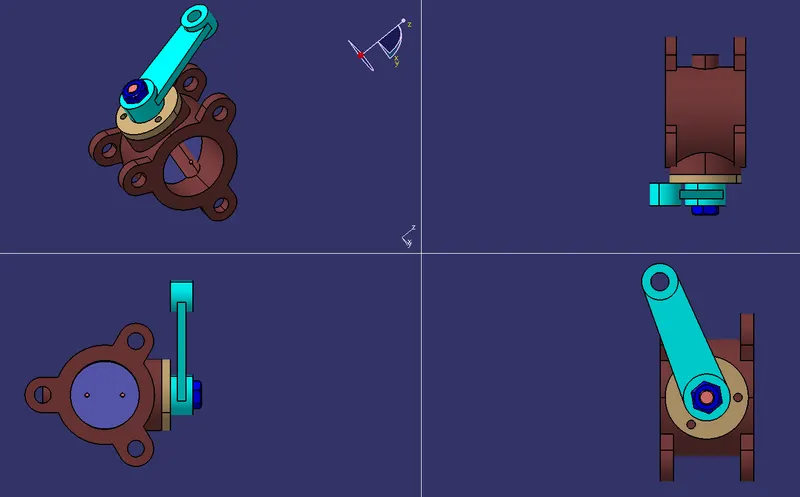
Assembly of Butterfly Valve:
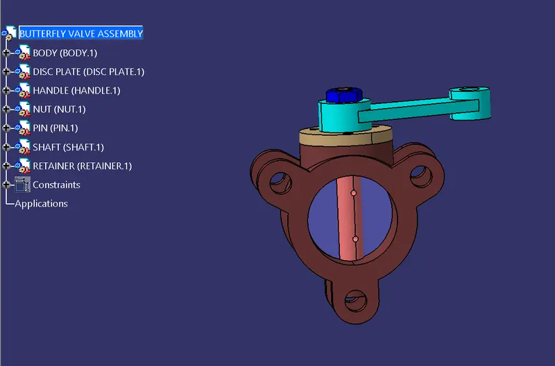
Drawing of Butterfly valve assembly
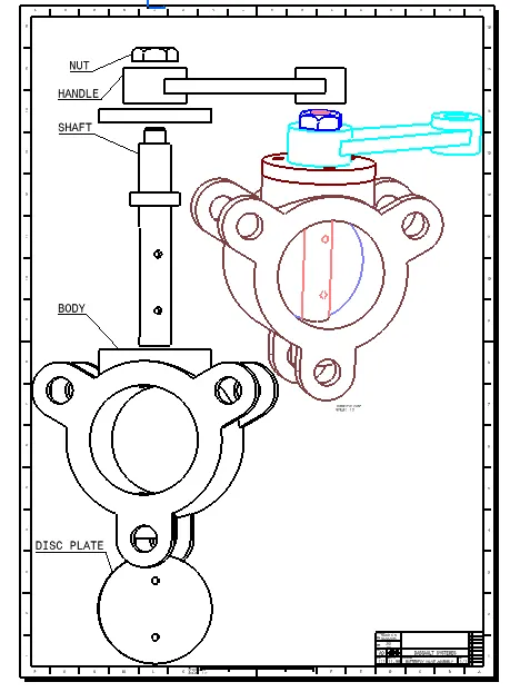
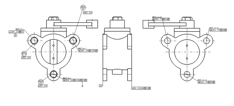
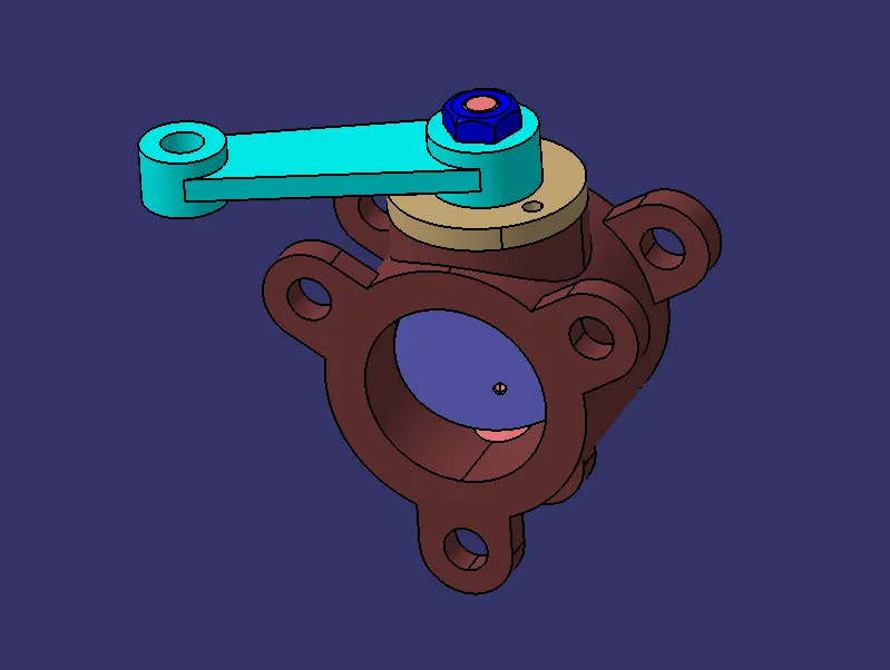
Conclusion:
Here, we designed Butterfly valve components and assembled all parts with porper contraints. Created Drawing for all parts and applied GD&T to individual components as well as assemblies of butterfly valve.