Week 14 challenge
OBJECTIVE:
- The goal is to design and assemble the butterfly valve components in SIEMENS NX CAD using various modelling and assembly features.
- Creating butterfly valve assembly drawing sheets with various drafting tools.
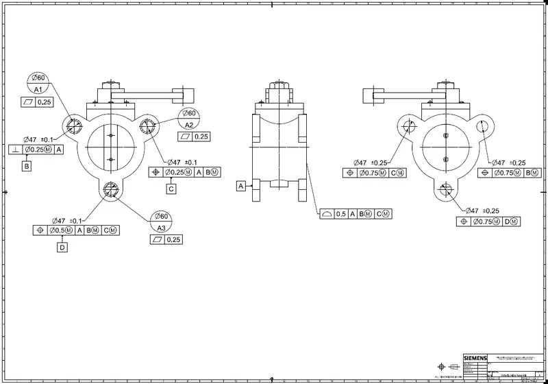
- Understanding and applying various GD&T symbols to the butterfly valve
INTRODUCTION:
A butterfly valve is a valve that isolates or regulates the flow of a fluid. The closing mechanism is a disk that rotates. A butterfly valve is from a family of valves called quarter-turn valves. In operation, the valve is fully open or closed when the disc is rotated a quarter turn. The "butterfly" is a metal disc mounted on a rod. When the valve is closed, the disc is turned so that it completely blocks off the passageway. When the valve is fully open, the disc is rotated a quarter turn so that it allows an almost unrestricted passage of the fluid. The valve may also be opened incrementally to throttle flow.
In operation, the valve is fully opened or closed when the disc is rotated a quarter turn. When the valve is closed, the disc is turned so that it completely blocks the passageway. And, when the valve is open the disc is rotated a quarter turn/90 deg so that it allows the unrestricted flow of the fluid. The valve may also be opened incrementally to throttle flow. Many different types of valves are used in flow control. They are used for a variety of reasons, such as phase (liquid or gases), pressure, piping restrictions, and solids content. Other valves are chosen for their capability to open and close in a quarter turn.
Early use of butterfly valves focused on water applications, but new designs and component materials have allowed them to be utilized in growing industrial fluid applications. Presently, butterfly valves can be found in almost every chemical plant handling a variety of diverse fluids.
PARTS OF BUTTERFLY VALVE
- Body
- Shaft/Stem
- Disc Plate
- Lever Handle
- Retainer
- Nut
- Bolt
DESIGN AND METHODOLOGY
1. BODY OF BUTTERFLY VALVE
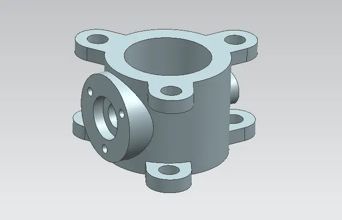
The body is the housing for the internal components and it is the main part of the butterfly valve. The body connects to two pipes on its two sides and it regulates to flow. For the creation of this part, simple features like to revolve, extrude, and move objects are used in the modeling application of NX.
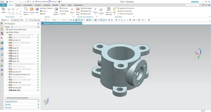
Front View:
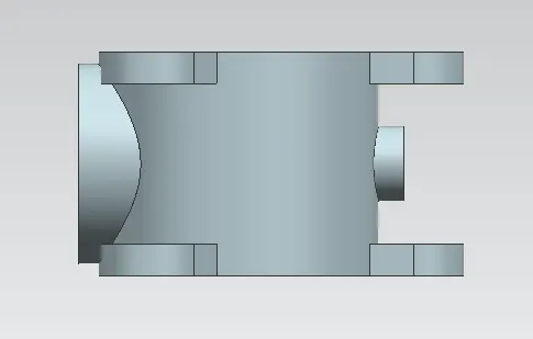
Side View:
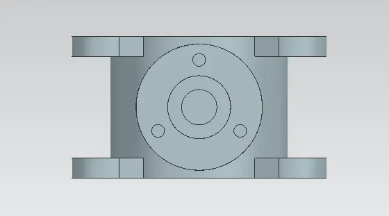
Top View:
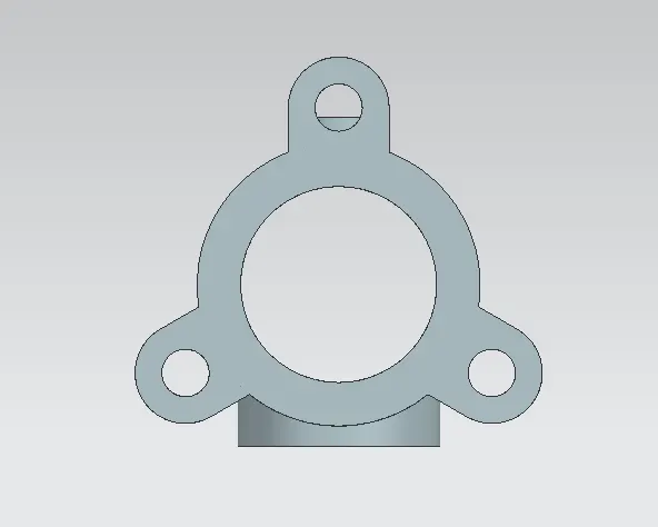
Isometric View:
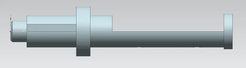
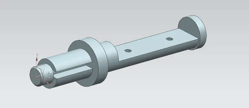
2. SHAFT/STEM OF BUTTERFLY VALVE
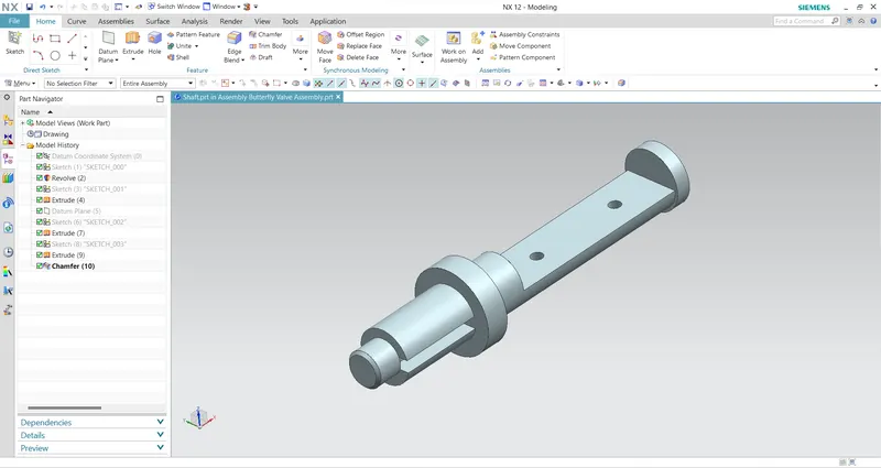
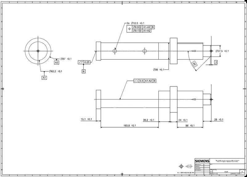
It is another important component of the butterfly valve. It inserts into the body of the valve and sits perpendicular to the direction of flow. It holds the disc inside the body and is clamped with the lever outside the body. It is created using simple features like revolve and extrudes features in the NX modeling environment. After the part creation is completed, the drawing is created in the drafting application of NX, and GD&T is applied using the features of NX. For this shaft, position tolerance should be given to the holes which hold the disc, a profile of the surface should be applied to the surface where the disc sits, and position tolerance for the cylindrical body of the shaft concerning the defined datums. Composite position tolerance is applied in the case of disc positioning holes as it repeats creating a pattern.
Front View:
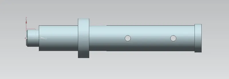
Side View:
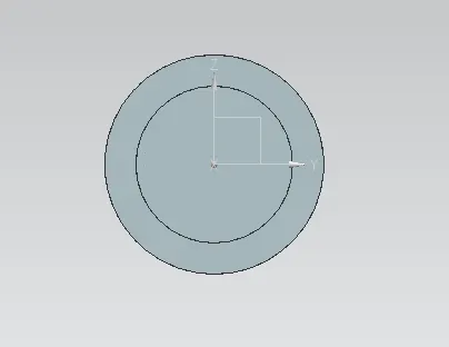
Top View:
Isometric View:
Drawing Sheet:
3. DISC PLATE OF BUTTERFLY VALVE
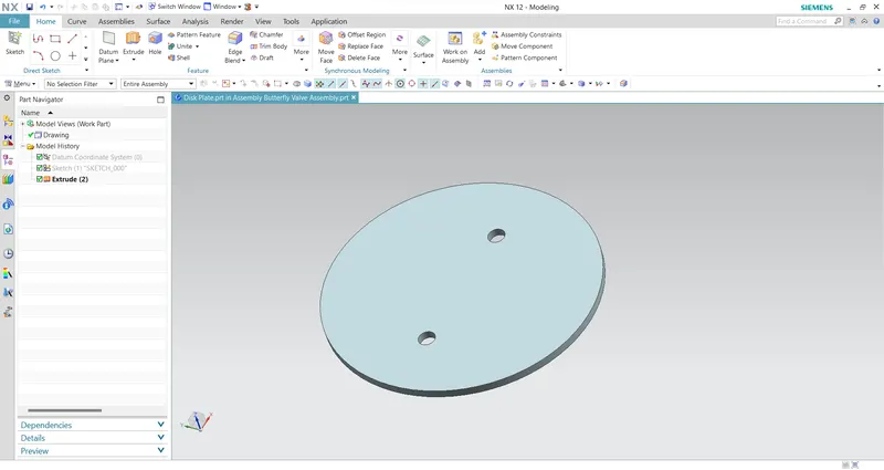
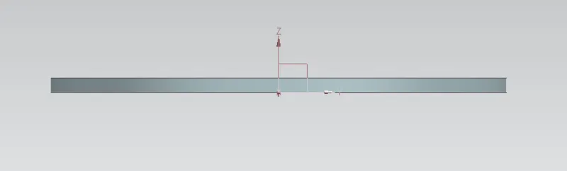
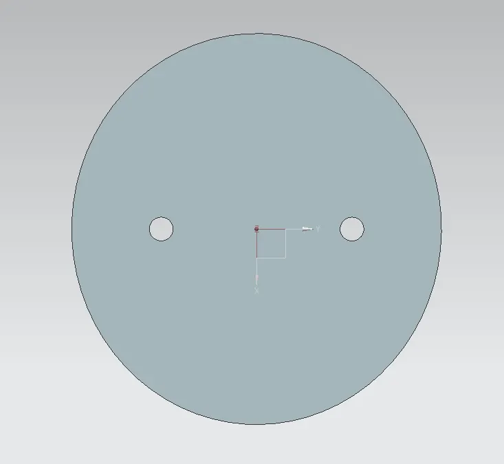
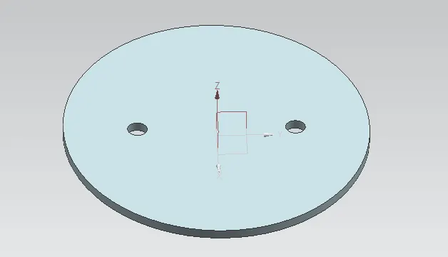
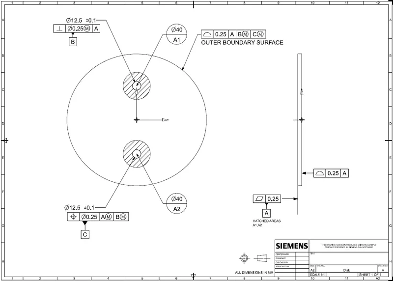
This disc plate is the main component of the butterfly valve which regulates the flow in the valve. The orientation of this disc determines the flow rate of the fluid. It is not perfectly circular, rather it is elliptical in profile. The holes in it help to position it properly on the shaft created earlier. A simple feature like extrude can create this part in NX. To apply GD&T for this part, the primary datum is defined on the surface where it comes in contact with the surface of the shaft, and perpendicular and perpendicular tolerances are applied as per the requirement. As the cost increases, while machining the entire contact surface, small circular datum targets are created and GD&T is applied to reduce the manufacturing cost.
Front View:
Top View:
Isometric View:
Drawing Sheet:
4. LEVER HANDLE OF BUTTERFLY VALVE
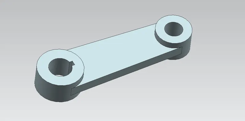
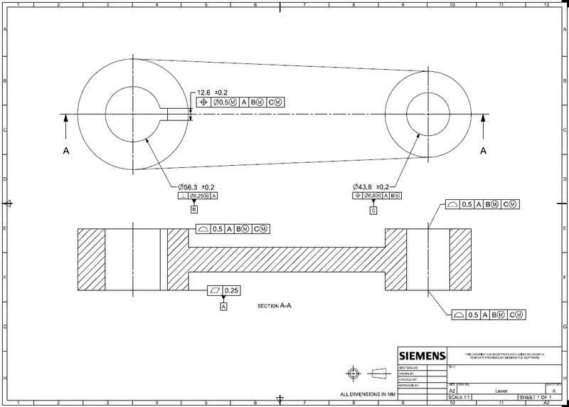
A lever is a handle that is used to rotate to regulate the flow. It is attached to the shaft with the help of a key to fixing it in position concerning it. So when it is rotated, the shaft rotates which in turn rotates the disc and regulates the flow inside the pipe. It is created using simple features like extrude in NX after the proper base sketch is created. For the application of GD&T on the lever, a section view is also created to show how different datums are defined and tolerances are provided. Position tolerance is applied to the proper holes after the perpendicular tolerance is applied to the first hole. To control the key slot, small tolerance is applied to the width of it. Profile tolerances are provided to the surfaces which come to contact with other parts as per the requirement.
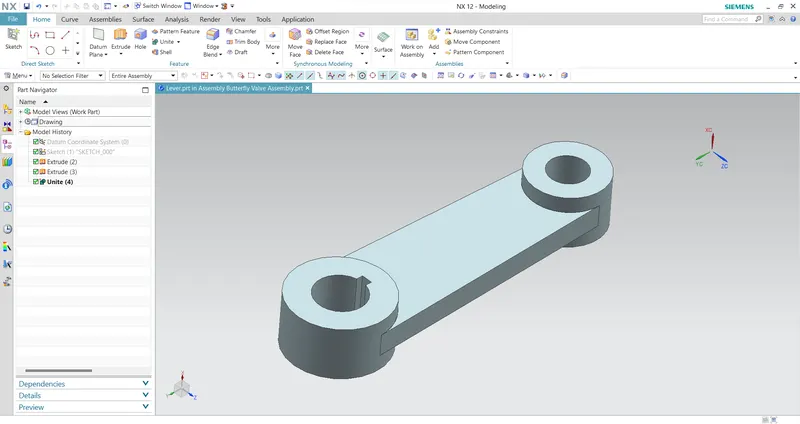
Front View:
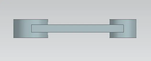
Side View:
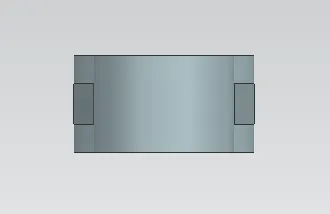
Top View:
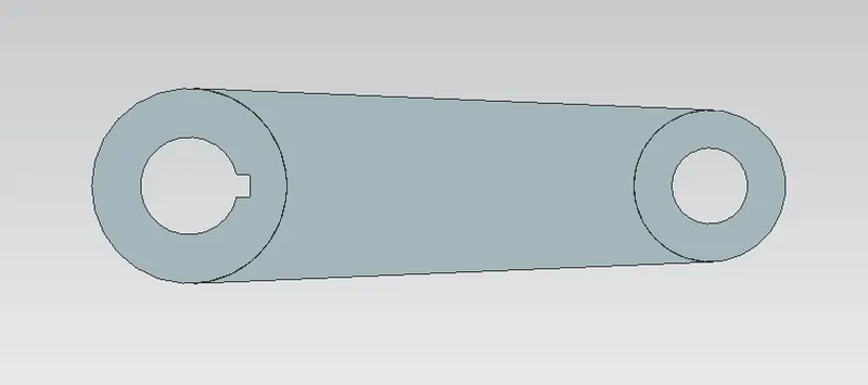
Isometric View:
Drawing Sheet:
5. RETAINER OF BUTTERFLY VALVE
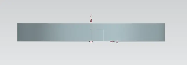
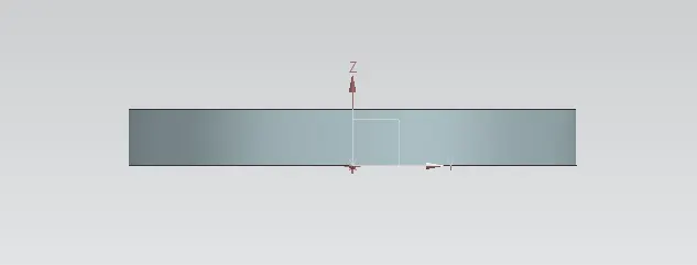
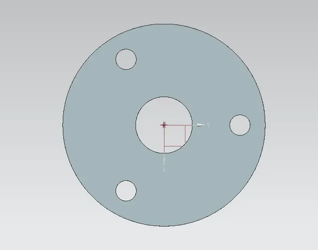
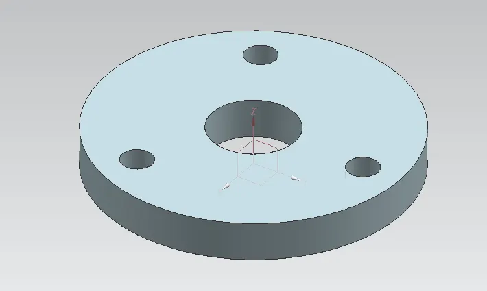
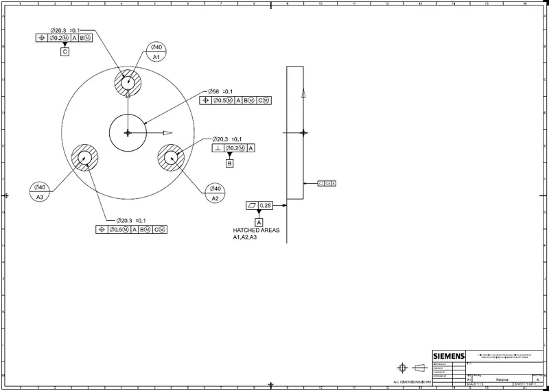
This part helps to retain or to fix the shaft with the body of the butterfly valve. It prevents the shaft from coming out of the body and keeps it in position for the proper functioning of the disc inside the body. The creation of the retainer plate involves only a simple feature like extrude in NX. For the GD&T application in the retainer plate, similar steps are followed as in the case of the disc. Primary, secondary and tertiary datums are defined properly as per the design intent, and datum targets are applied to the holes. Perpendicular and position tolerances are applied to lock the DOF of the retainer in position. A profile tolerance is also applied to control the upper surface of the retainer.

Front View:
Side View:
Top View:
Isometric View:
Drawing Sheet:
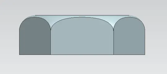
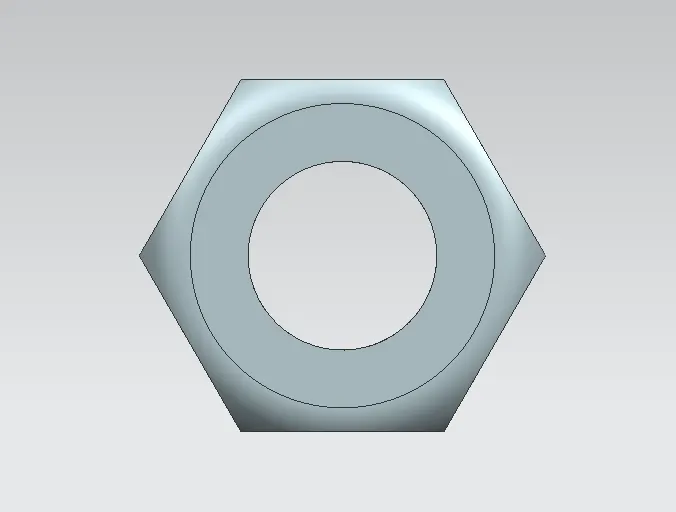
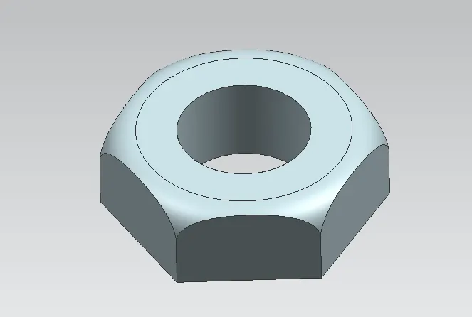
6. NUT - BUTTERFLY VALVE
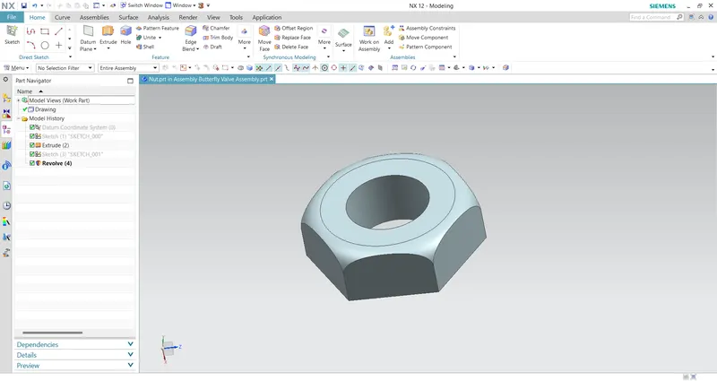
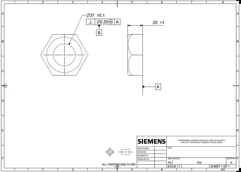
It is the last part that helps to fix the lever in position with the stem. It allows to keep it in position or to disassemble whenever required. It is created using simple extrude and revolve features in NX. To apply GD&T for this nut, the primary datum is defined on the surface which comes in contact with the lever. Perpendicular tolerance is applied to the hole or the thread and is defined as datum B. Size tolerance is also applied to the thickness of the nut.
Front View:
Top View:
Isometric View:
Drawing Sheet:
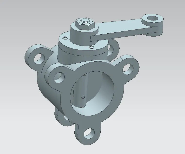
Butterfly Valve Assembly
After the design, all the models should assemble with appropriate constraints. The assembly is created by first placing the body in position and mating other parts to it with the application of different joints provided in NX. First, the shaft and disc are joined together with the screws in place to create a sub-assembly which is then joined to the body in position. The retainer plate is then mated with the body and screws are used to fix them. After that, the lever is mated to the shaft in a position that is then fixed after the nut is mated with the shaft.
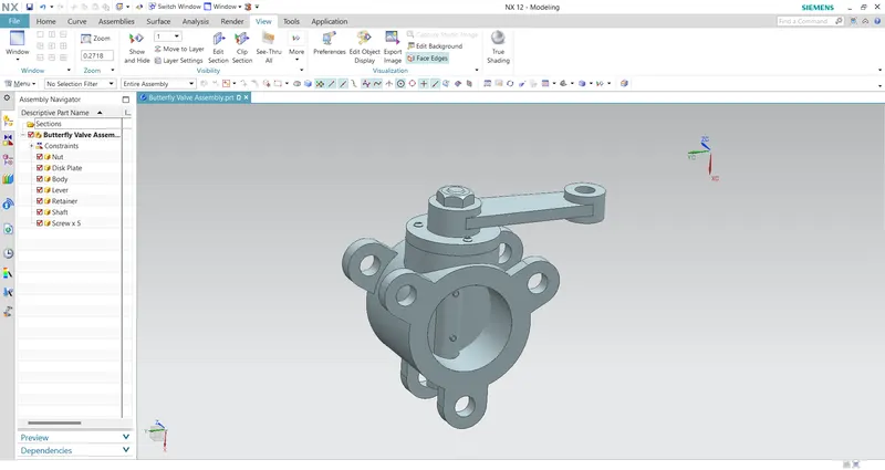
Front View:
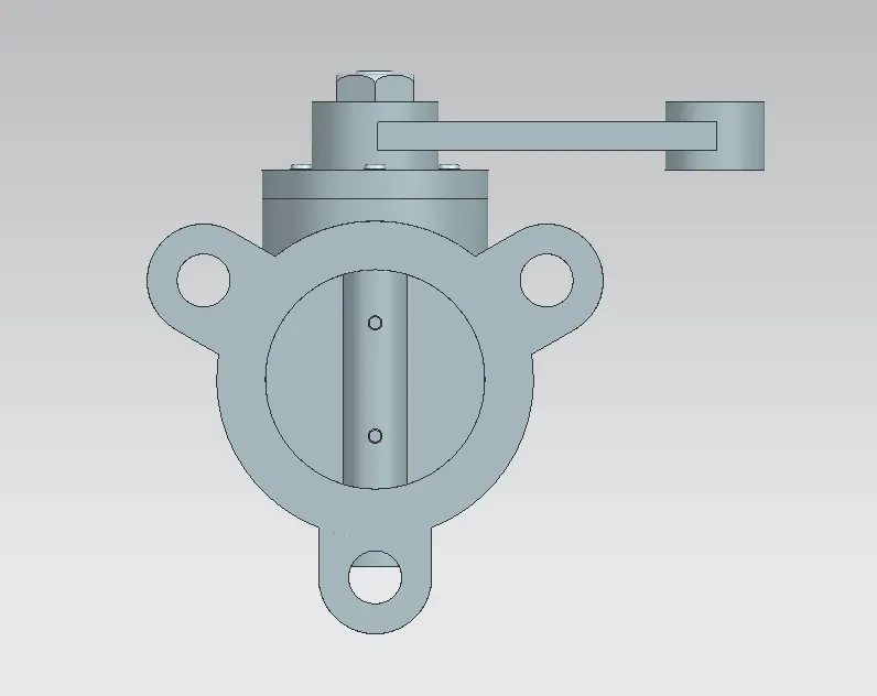
Side View:
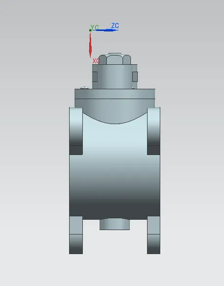
Top View:
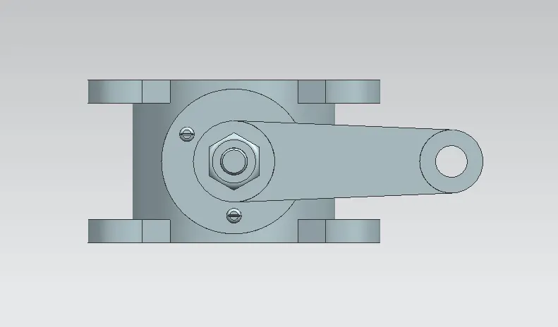
Isometric View:
Drawing Sheet:
CONCLUSION:
In this project, a butterfly valve is designed and assembled in parametric CAD software, Siemens NX. A design process in a real industrial manner is followed in this design of butterfly valve understanding the design process more with the application of GD&T with industrial standards.