Week 14 challenge
Week 14 challenge
Objective:
- To created the 3D part of the butterfly valve sub part name like Body, Shaft, Lever, Nut, Retainer, Disc Plate etc.
- To apply GD&T to the butterfly valve assembly drawing.
- To understand the concept of Geometric Dimensioning and Tolerancing.
A Butterfly valve is used to stop, regulate, and start flow. Butterfly valves are easy and fast to open. A 90° rotation of the handle provides a complete closure or opening of the valve. Butterfly valves are especially well-suited for the handling of large flows of liquids or gases at relatively low pressures and for the handling of slurries or liquids with large amounts of suspended solids. Butterfly valves are built on the principle of a pipe damper. The flow control element is a disk of approximately the same diameter as the inside diameter of the adjoining pipe, which rotates on either a vertical or horizontal axis. When the disk lies parallel to the piping run, the valve is fully opened and when the disk becomes perpendicular position, the valve is shut. Intermediate positions, for throttling purposes, can be secured in place by some locking mechanisms.
GD &T is a system for defining and communicating design intent and engineering tolerances that helps engineers and manufacturers optimally control variations in manufacturing processes.
GD &T offers some advantages e.g
- Saving Money — GD&T enhances design accuracy by allowing for appropriate tolerances that maximize production.
- For many projects, the process provides extra or bonus tolerances, further increasing cost effectiveness.
Design methodology:
- Create sketches to make 3-D parts in NX CAD modeling workbench.
- Create drawing for 3-D parts in NX-CAD Drafting workbench.
- Apply GD and T on individual parts.
- Switch to assembly workbench and create an assembly of these parts.
- Create drawing for assembly in NX-CAD Drafting workbench.
- Apply GD and T on assembly
After modeling each part in 3-D, create an assembly file, load all the components and position them in desired orientation.
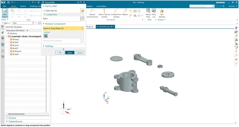
Fig.1
After positioning, assemble them and then switch to drafting workbench.
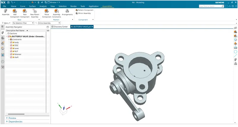
Fig.2
On one of the surface define the datum target area as shown below and name this datum as A.
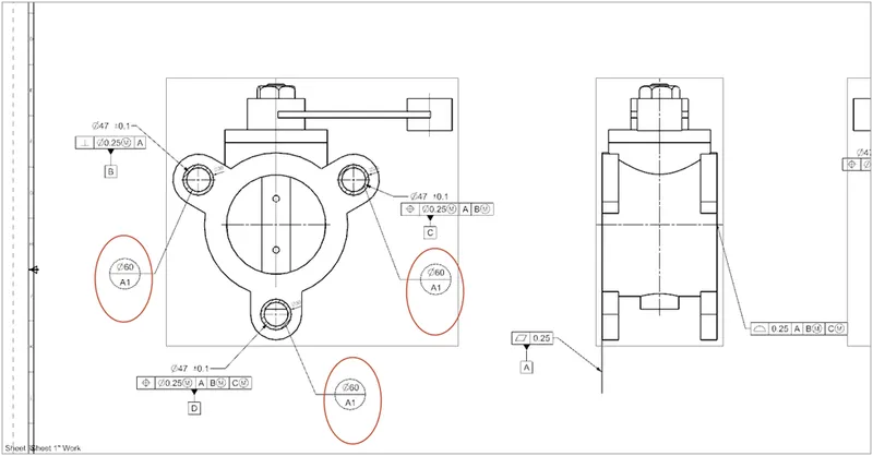
Fig.3
Give flatness to this surface to control the flatness of datum target areas.
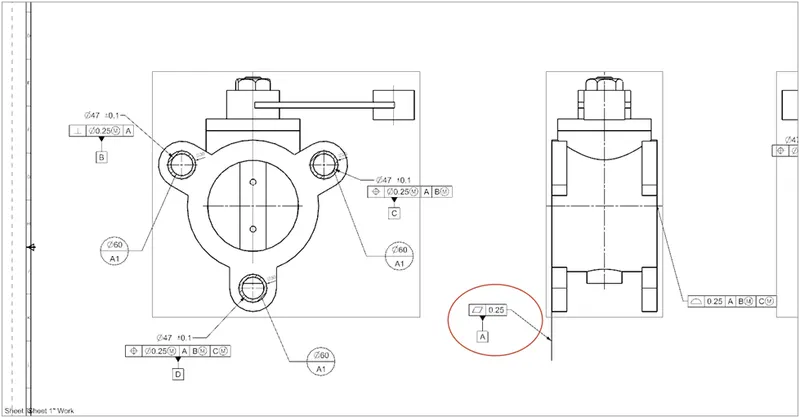
Fig.4
Define perpendicularity tolerance for hole with respect to datum A and name it as datum B.
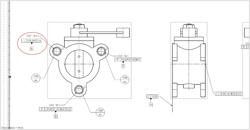
Fig.5
Define position tolerance for the second hole and define it as datum C.
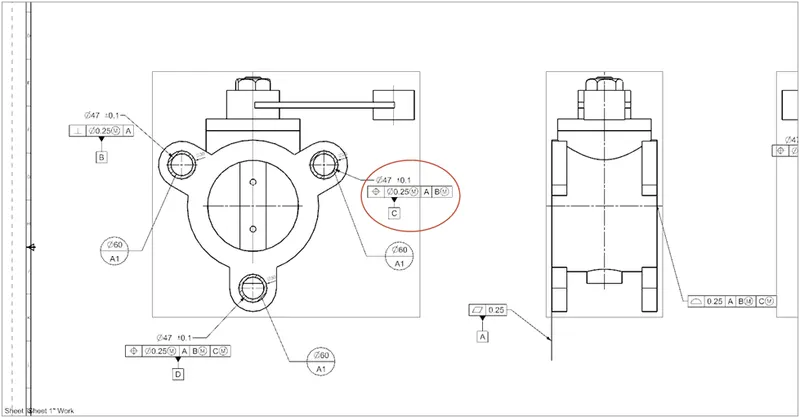
Fig.6
Again define position tolerance for the third hole and name it as datum D. This datum D along with datum A, B and C will help in controlling the position of the holes located on the opposite surface.
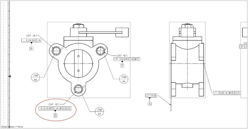
Fig.7
Use the profile of surface tolerance to control the profile of surface opposite to surface A.
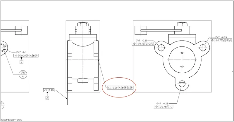
Fig.8
Use position tolerance for the holes located on opposite surface of datum A with respect to respective datum as shown below.
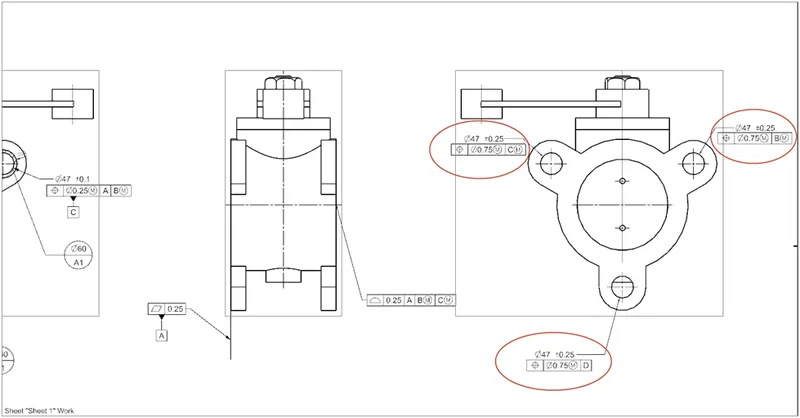
Fig.9
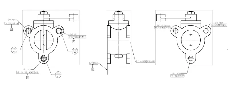
Fig.10
Final drafting sheet with applied GD & T.