Week 14 challenge
OBJECTIVES:
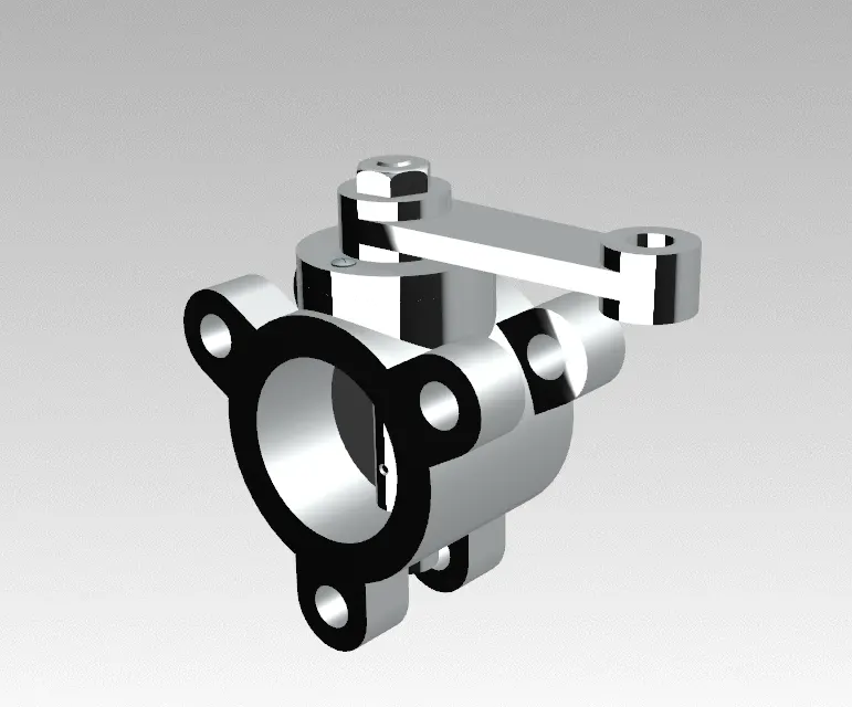
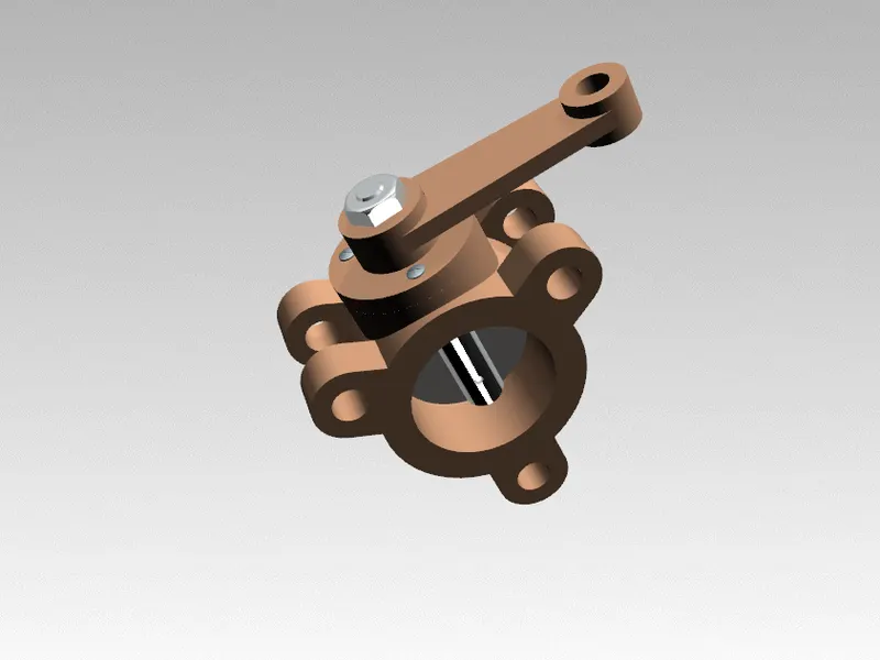
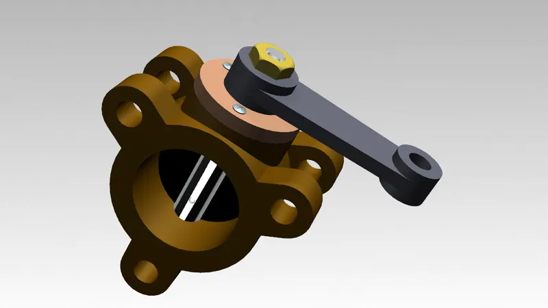
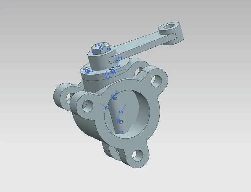
The objective of this project is that design the all parts of butterfly valve separately and assemble and create the butterfly valve by the help of multiple comments by the siemens NX.
INTRODUCTION:
Butterfly valve:
Butterfly valves are a family of quarter turn rotational motion valves which are used in pipelines to shut off flow. It can be to regulate the flow. In this valve metal disc is mounded on the shaft. It is called as butterfly. When the disk is closed with the main body, it will block off passageway. When the disk is opened, it will allow passage of the fluid. There are different kinds of butterfly valve which adapted for different pressure and usage.
GD&T:
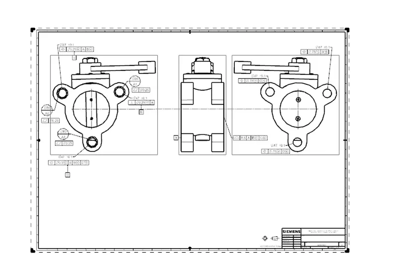
GD&T means Geometric dimensioning and tolerancing. It is a system for defining and communicating engineering tolerances. It is used a symbolic language on engineering and computer generated three dimensional solid models. It explicitly describes nominal geometry and allowable variations. It gives details to the machine operators. GD&T gives geometry of parts and assemblies, to define allowable variation in forms and possible size of the features and give allowable variation between features.
There are several standards available worldwide that describe the symbols and define the rules in GD&T. One such standard is American Society of Mechanical Engineers (ASME) Y14.5 Which provides a fairly complete set of standers for GD&T. Another standard is International Organization for Standardization (ISO) which typically only address a single topic at a time.
Advantages of GD&T:
- Saving money
- Assisting digital design method
- Offering uniformity and convenience
- Ensuring dimensional and tolerance requirements
- Provide accurate communication
Designing software:
In this project we use NX CAD software which is one of the Computer Aided Designing software which is used to create 3D modelling, assembly the parts and drawing etc. It supports the product developing and manufacturing at all stage of life cycle.
Design Tools:
- Sketch:
It is used draw 2D sketch with respect plane to create the 3D model.
- Extrusion:
It is used to extrude the sketch in one or two directions to for the 3D model Add option used to add and subtract option is used to remove the portions.
- Revolve:
It is a one of the options to create the solid model by rotating the sketch
- Chamfer:
This tool is used to avoid the sharp edges.
Assembly tools:
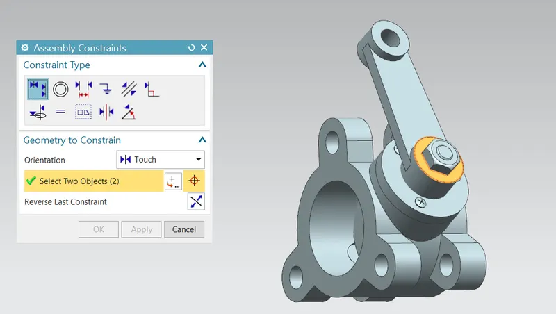
We need to give constrain the parts to assemble wit another parts.
- Infer axis/centre:
This is used to align the two parts with the help of centre axis.
- Touch:
This is used to give touch between two parts.
Drafting:
It is a different workbench in which workbench create the 2D drawing and give the dimension and GD &T to the parts. Add option used to add and subtract option is used to remove the portions.
2D Drawing:
It is 2D drawing with dimensions. By this value is used to design the butterfly valve main body.
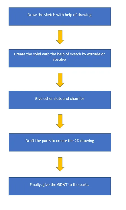
DESIGNING MTHODOLOGY:
FOR PARTS:
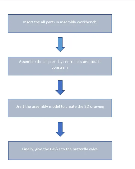
FOR ASSEMBLY:
DESIGNING:
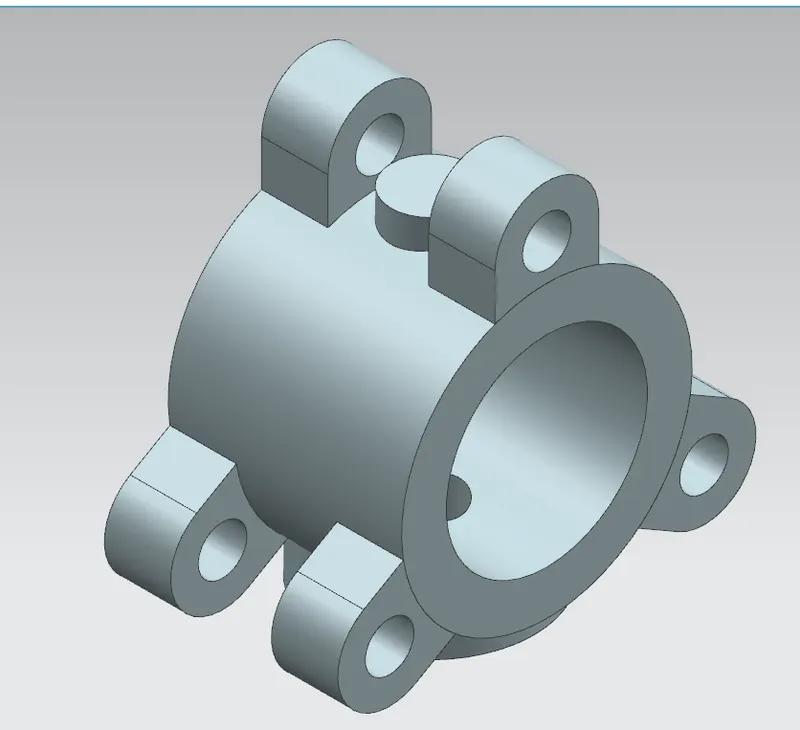
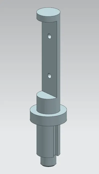
First design the all parts separately with help of extrude, revolve, move component, chamfer etc. Following parts are created for butterfly valve assembly.
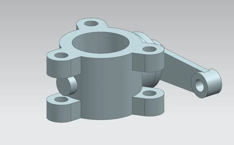
- Main body
2. Shaft
3. Retainer
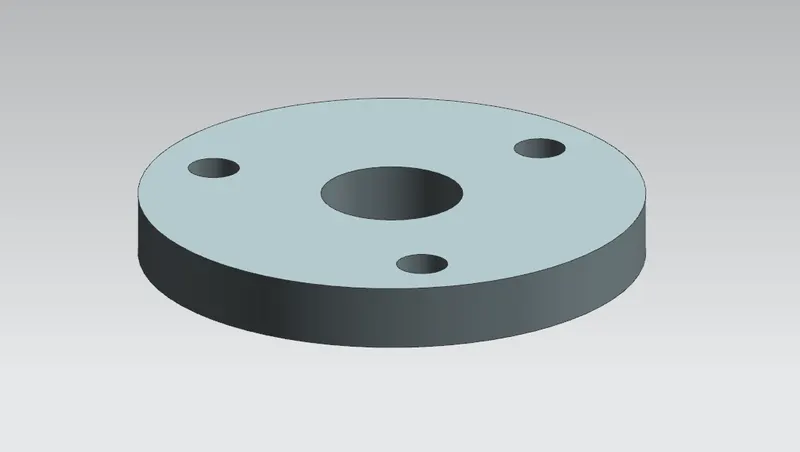
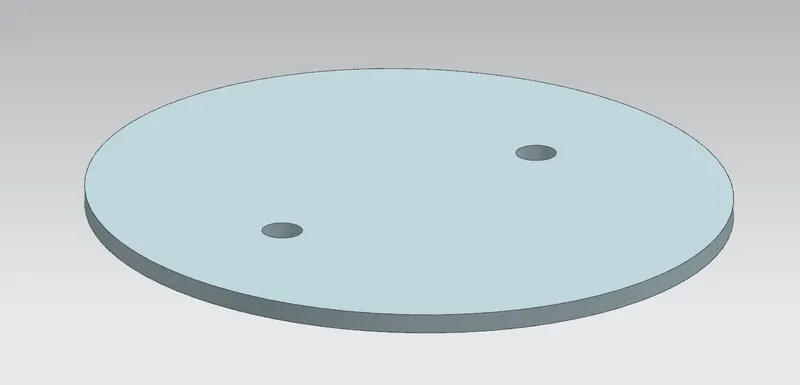
4. Disk
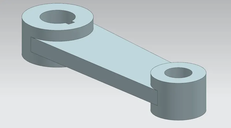
5. Lever
6. Nut:

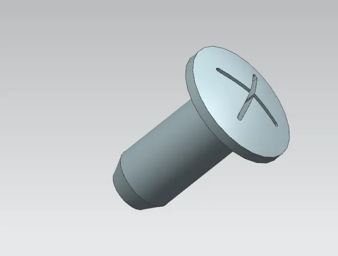
6. Bolt:
Assembling:
Created parts are assembled in the assembly workbench.
Drafting& GD&T:
First create the drafting then give the GD&T to the butterfly valve.
CONCLUSION:
Parts of butterfly valve is successfully created and assembled and GD&T are successfully given by Siemen NX.
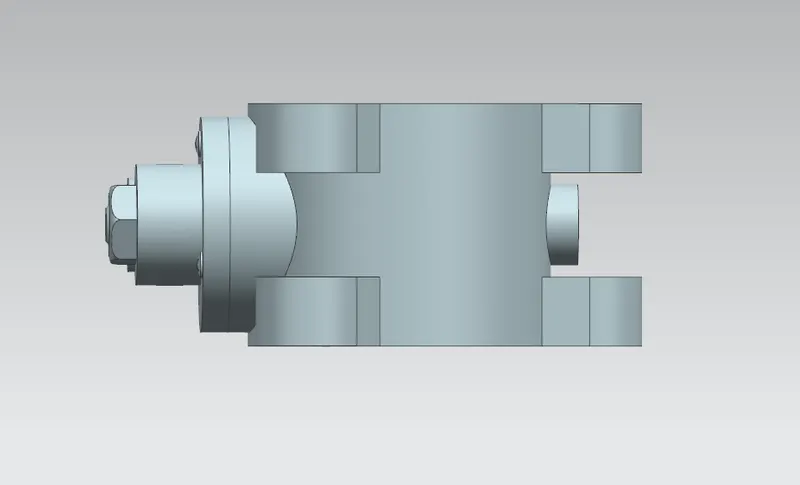
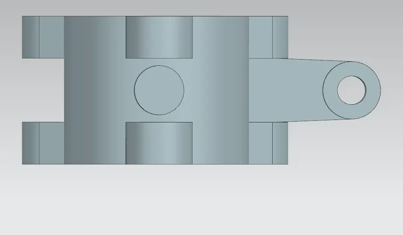
Different types of views:
Rendering view: