Week 12 - Validation studies of Symmetry BC vs Wedge BC in OpenFOAM vs Analytical H.P equation
Symmetry Vs Wedge BC for a pipe-flow simulation in OpenFOAM
Objective:
The main aim of this project is to compare the results obtained by using symmetry and wedge Boundary condition (BC) for simulating the pipe-flow problem in OpenFOAM with analytical solution. The simulation was performed for 3 different wedge angles using both the boundary condition separately.
Introduction:
The pipe-flow problem is a fundamental problem in fluid dynamics and this internal flow through the pipe is axisymmetric in nature. Hence the 3D problem is converted into 2D and only a small wedge is simulated. The following figure shows a schematic representation of the wedge geometry.
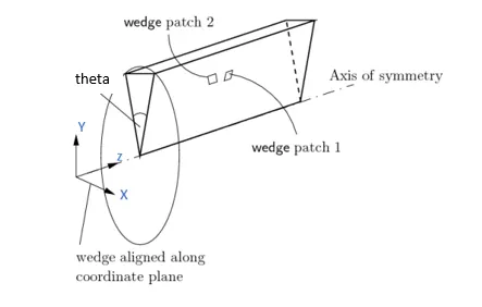
The parameters used in this simulation were
|
Parameter |
Value |
|
Diameter of pipe |
`0.1 m` |
|
Length of pipe |
`12 m` |
|
Wedge angle |
`5 deg` |
|
Working fluid |
Water @ `20°C` |
|
Density |
1000 `Kg/m^3` |
|
Dynamic viscosity |
`1*10^-3` `Pa-s` |
|
Inlet Reynolds number |
`2100` |
For solving such a problem, two types of Boundary conditions are offered by OpenFOAM: Symmetry and Wedge.
Symmetry BC:
This BC defines a mirror face/surface and it should be used only if the physical object or geometry and the expected flow field pattern of the developed solution are mirrored along that surface [1]. This BC can be applied to both planar and non-planar faces.
The following conditions are applied on the flow variables when a Symmetry BC is used:
- The flux across the symmetry is zero
- The normal components of all the variables are set to zero
Wedge BC
The wedge boundary condition defines an axisymmetric boundary condition such that all the flow variables have the same value at any angle. In other words, the flow variables vary only in the axial and radial direction. This boundary condition must be specified by two planes on either side of the centreline.
In this project, the flow is simulated for 3 different wedge angles: 10,25 and 45. Each case is simulated with two boundary condition and then their results were compared with the analytical solution obtained from Hagen-Poiseillis equation [2]
Mesh Generation:
The mesh for this case was generated using the blockMesh feature of OpenFOAM and the following matlab script was used to create the blockMeshDict file
%% script to generate the blockMeshDict file
clear all
close all
clc

%% inputs
filename="wedge_blockMeshDict_45";
axisSymBC = 'wedge';

length = 12; %m
wedgeAngle = 10; %deg
dia = 0.1; % m
convertToMeters=1; % [-]

x_dis = (dia/2)*sind(wedgeAngle/2);
y_dis = (dia/2)*cosd(wedgeAngle/2);

% Vertices
v(1).name = '0';
v(1).coord = [0 0 0];

v(2).name = '1';
v(2).coord = [x_dis,y_dis,0];

v(3).name = '2';
v(3).coord = [-x_dis,y_dis,0];

v(4).name = '3';
v(4).coord = [0 0 length];

v(5).name = '4';
v(5).coord = [x_dis,y_dis,length];

v(6).name = '5';
v(6).coord = [-x_dis,y_dis,length];

% blocks
blocks(1).type = 'hex';
blocks(1).value = [0 0 1 2 3 3 4 5];
blocks(1).numCells = [1 20 100];
blocks(1).gradingType = 'simpleGrading';
blocks(1).gradingValue = [1 1 1];

% boundary faces
bc(1).name = 'inlet';
bc(1).type = 'patch';
bc(1).faces = [0 0 2 1];

bc(2).name = 'outlet';
bc(2).type = 'patch';
bc(2).faces = [3 4 5 3];

bc(3).name = 'outerWall';
bc(3).type = 'wall';
bc(3).faces = [2 5 4 1];

bc(4).name = 'front';
bc(4).type = axisSymBC;
bc(4).faces = [5 2 0 3];

bc(5).name = 'back';
bc(5).type = axisSymBC;
bc(5).faces = [0 1 4 3];

bc(6).name = 'axis';
bc(6).type = 'empty';
bc(6).faces = [3 3 0 0];

%%


fileId = fopen(filename,'w');
% file header
fprintf(fileId,'%s\n','/*--------------------------------*- C++ -*----------------------------------*\');
fprintf(fileId,'%s\n','  =========                 |');
fprintf(fileId,'%s\n','  \\      /  F ield         | OpenFOAM: The Open Source CFD Toolbox');
fprintf(fileId,'%s\n','   \\    /   O peration     | Website:  https://openfoam.org');
fprintf(fileId,'%s\n','    \\  /    A nd           | Version:  6');
fprintf(fileId,'%s\n','     \\/     M anipulation  |');
fprintf(fileId,'%s\n',' \*---------------------------------------------------------------------------*/');
fprintf(fileId,'%s\n',' FoamFile');
fprintf(fileId,'%s\n',' {');
fprintf(fileId,'%s\n','     version     2.0;');
fprintf(fileId,'%s\n','     format      ascii;');
fprintf(fileId,'%s\n','     class       dictionary;');
fprintf(fileId,'%s\n','     object      blockMeshDict;');
fprintf(fileId,'%s\n',' }');
fprintf(fileId,'%s\n','// * * * * * * * * * * * * * * * * * * * * * * * * * * * * * * * * * * * * * //');
fprintf(fileId,'%s\n',' ');
fprintf(fileId,'%s\t%0.4f%s\n','convertToMeters',convertToMeters,';');
fprintf(fileId,'%s\n',' ');

for i=1:size(v,2)
    last=false;
    if i==size(v,2)
        last=true;
    end
    writeVertices(fileId,i,v(i),last);
end

for i=1:size(blocks,2)
    last=false;
    if i==size(blocks,2)
        last=true;
    end
    writeBlocks(fileId,i,blocks(i),last);
end

% edges
fprintf(fileId,'%s\n','edges');
fprintf(fileId,'%s\n','(');
fprintf(fileId,'%s\n',');');
fprintf(fileId,'%s\n',' ');

for i=1:size(bc,2)
    last=false;
    if i==size(bc,2)
        last=true;
    end
    writeBCs(fileId,i,bc(i),last);
end

% Merge Patches
fprintf(fileId,'%s\n','mergePatchPairs');
fprintf(fileId,'%s\n','(');
fprintf(fileId,'%s\n',');');
fclose(fileId);


%% functions
function writeVertices(fileId,num,v,last)
    if num == 1
        fprintf(fileId,'%s\n','vertices ');
        fprintf(fileId,'%s\n','(');
    end
    fprintf(fileId,'\t( %0.4f %0.4f %0.4f )\t%s%s\n',v.coord,'//',v.name);
    if last

        fprintf(fileId,'%s\n',');');
        fprintf(fileId,'%s\n',' ');

    end

end

function writeBlocks(fileId,num,block,last)

    if num == 1
        fprintf(fileId,'%s\n','blocks ');
        fprintf(fileId,'%s\n','(');
    end
    fprintf(fileId,'\t%s (%d %d %d %d %d %d %d %d) (%d %d %d) %s (%d %d %d)\n',block.type,block.value,block.numCells,block.gradingType,block.gradingValue);
    if last

        fprintf(fileId,'%s\n',');');
        fprintf(fileId,'%s\n',' ');

    end

end

function writeBCs(fileId,num,bc,last)
    if num == 1
        fprintf(fileId,'%s\n','boundary ');
        fprintf(fileId,'%s\n','(');
    end
    fprintf(fileId,'\t%s\n',bc.name);
    fprintf(fileId,'\t%s\n','{');
    fprintf(fileId,'\t\t%s\t%s%s\n','type',bc.type,';');
    fprintf(fileId,'\t\t%s\n','faces');
    fprintf(fileId,'\t\t%s\n','(');
    fprintf(fileId,'\t\t\t(%d %d %d %d)\n',bc.faces);
    fprintf(fileId,'\t\t%s\n',');');
    fprintf(fileId,'\t%s\n','}');
    if last

        fprintf(fileId,'%s\n',');');
        fprintf(fileId,'%s\n',' ');

    end

end
The blockMeshDict file produced from the above program is shown in the code snippet below
/*--------------------------------*- C++ -*----------------------------------*\
  =========                 |
  \\      /  F ield         | OpenFOAM: The Open Source CFD Toolbox
   \\    /   O peration     | Website:  https://openfoam.org
    \\  /    A nd           | Version:  6
     \\/     M anipulation  |
 \*---------------------------------------------------------------------------*/
 FoamFile
 {
     version     2.0;
     format      ascii;
     class       dictionary;
     object      blockMeshDict;
 }
// * * * * * * * * * * * * * * * * * * * * * * * * * * * * * * * * * * * * * //

convertToMeters	1.0000;

vertices
(
	( 0.0000 0.0000 0.0000 )	//0
	( 0.0044 0.0498 0.0000 )	//1
	( -0.0044 0.0498 0.0000 )	//2
	( 0.0000 0.0000 12.0000 )	//3
	( 0.0044 0.0498 12.0000 )	//4
	( -0.0044 0.0498 12.0000 )	//5
);

blocks
(
	hex (0 0 1 2 3 3 4 5) (1 20 100) simpleGrading (1 1 1)
);

edges
(
);

boundary
(
	inlet
	{
		type	patch;
		faces
		(
			(0 0 2 1)
		);
	}
	outlet
	{
		type	patch;
		faces
		(
			(3 4 5 3)
		);
	}
	outerWall
	{
		type	wall;
		faces
		(
			(2 5 4 1)
		);
	}
	front
	{
		type	wedge;
		faces
		(
			(5 2 0 3)
		);
	}
	back
	{
		type	wedge;
		faces
		(
			(0 1 4 3)
		);
	}
	axis
	{
		type	empty;
		faces
		(
			(3 3 0 0)
		);
	}
);

mergePatchPairs
(
);
The wedge was changed and the blockMeshDict for the other wedgeAngles were produced and used in the simulation.
The Boundary conditions used in this simulation are shown in the following code-snippets. The only change is the type used for front and back faces where symmetry condition will be used for a symmetry case.
/*--------------------------------*- C++ -*----------------------------------*\
  =========                 |
  \\      /  F ield         | OpenFOAM: The Open Source CFD Toolbox
   \\    /   O peration     | Website:  https://openfoam.org
    \\  /    A nd           | Version:  6
     \\/     M anipulation  |
\*---------------------------------------------------------------------------*/
FoamFile
{
    version     2.0;
    format      ascii;
    class       volVectorField;
    object      U;
}
// * * * * * * * * * * * * * * * * * * * * * * * * * * * * * * * * * * * * * //

dimensions      [0 1 -1 0 0 0 0];

internalField   uniform (0 0 0);

boundaryField
{
    inlet
    {
        type            fixedValue;
        value           uniform (0 0 0.021);
    }

    outlet
    {
        type            zeroGradient;
    }
    outerWall
    {
	type		noSlip;
    }

    front
    {
        type            wedge;
    }

    back
    {
        type            wedge;
    }
    axis
    {
	type		empty;
    }

}

// ************************************************************************* //
Pressure:
/*--------------------------------*- C++ -*----------------------------------*\
  =========                 |
  \\      /  F ield         | OpenFOAM: The Open Source CFD Toolbox
   \\    /   O peration     | Website:  https://openfoam.org
    \\  /    A nd           | Version:  6
     \\/     M anipulation  |
\*---------------------------------------------------------------------------*/
FoamFile
{
    version     2.0;
    format      ascii;
    class       volScalarField;
    object      p;
}
// * * * * * * * * * * * * * * * * * * * * * * * * * * * * * * * * * * * * * //

dimensions      [0 2 -2 0 0 0 0];

internalField   uniform 0;

boundaryField
{
    inlet
    {
        type            zeroGradient;
    }

    outlet
    {
        type            fixedValue;
	value		uniform 0;
    }
    outerWall
    {
	type		zeroGradient;
    }

    front
    {
        type            wedge;
    }
    back
    {
	type		wedge;
    }
    axis
    {
	type		empty;
    }
}

// ************************************************************************* //
Results and Discussion:
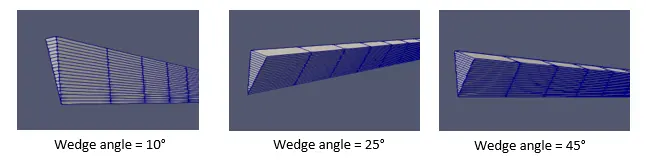
The above picture shows the various wedge angles and the corresponding wedge geometry used in this case. All the above geometry were generated using the blockMeshDict file created through the matlab script.
The analytical solution for this problem exists in the form of Hagel-Poiseuille equations.
Pressure-drop:
`Deltap=(8*mu*L*Q)/(pi*R^4)`
Where
`Deltap` - pressure drop in the cylindrical pipe in Pa
`mu` - dynamic viscosity in `Pa*s`
`L` - length of the pipe in `m`
`Q` - volumetric flow rate in `(m^3)/s`
`R` - radius of the pipe in `m`
Using this equation, the pressure is calculated as
`Deltap = (8*10^-3*12*pi*0.05^2*0.021)/(pi*0.05^4) = 0.8064 Pa`
Radial Velocity:
`u(r) = V_c*(1-(r^2)/(R^2))`
Where
`V_c = (Deltap*D^2)/(16*mu*l)` - is the centreline velocity in [m/s]
`R` - is the pipe radius in [m]
`u(r)` is the velocity along the radial direction in [m/s]
From the above formula,
`V_c = (0.8064*0.1^2)/(16*10^(-3)*12) = 0.042 m/s`
Wall shear stress:
`tau_w = (Deltap*D)/(4*L) = (0.8064*0.1)/(4*12) = 1.68*10^(-3)`
The following figures shows the results obtained from this simulation.
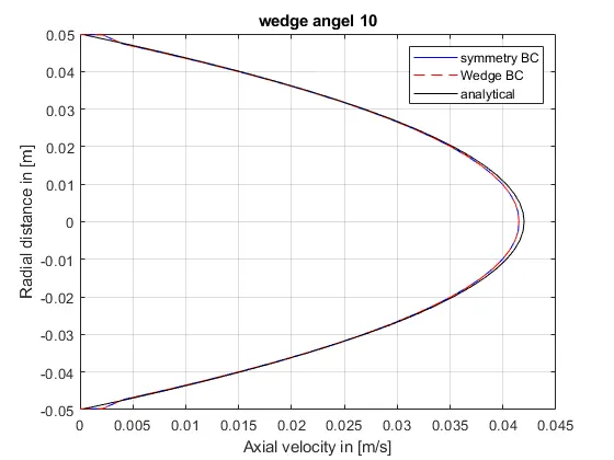
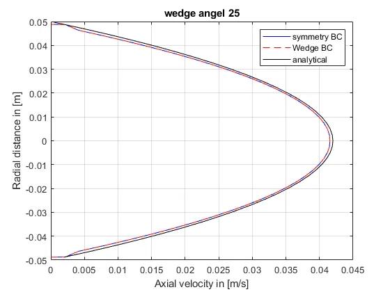
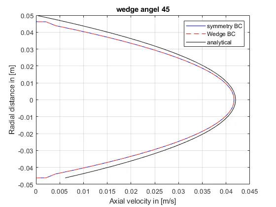
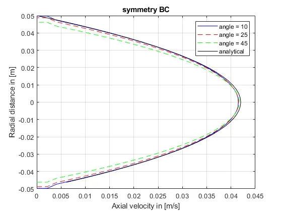
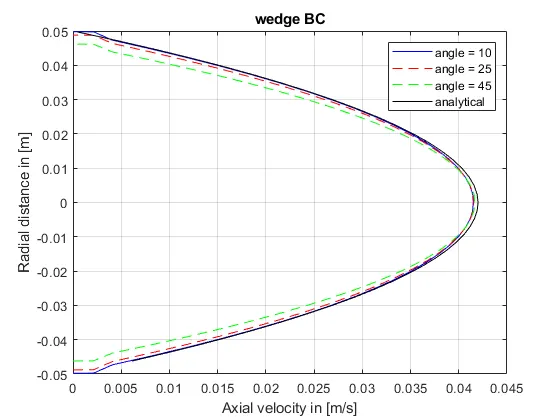
In the above figures, the velocity profile obtained from the usage of different boundary conditions is compared for different wedge angles. From the figures, it can be observed that there is no difference between the results obtained from using symmetry bc and wedge bc. The velocity profile results were close to the analytical results. However, as the wedge angle increased, the velocity values deviated more from the analytical results. This phenomenon can be observed more clearly from the figures below where the influence of wedge angle on the velocity is compared
The important results obtained from the simulation are summarized in the table below
Symmetry BC
|
Angle |
Wall Shear Stress (N/m²) |
Max Velocity (m/s) |
Simulation time (s) |
|
10 |
1.17e-3 |
0.0415 |
90.54 |
|
25 |
1.26e-3 |
0.0416 |
89.99 |
|
45 |
1.32e-3 |
0.0417 |
82.9 |
Wedge BC
|
Angle |
Wall Shear Stress (N/m²) |
Max Velocity (m/s) |
Simulation time (s) |
|
10 |
1.23e-3 |
0.0415 |
73 |
|
25 |
1.29e-3 |
0.0416 |
74 |
|
45 |
1.32e-3 |
0.0417 |
74.9 |
Conclusion:
Comparing the simulation results with the analytical results, it can be observed that both the boundary conditions produce the same results and the results are more accurate for smaller wedge angle. As the wedge angle increases, the geometry moves away from the true cylindrical geometry for which Hagen-Poiseuille’s equation is valid. The one thing to note is that the simulation was performed for a 2D-axisymmetric case with one cell along with the wedge.
It can also be observed that although the maximum velocity remains close to the one obtained from the HP equation, the overall radial velocity for the different wedges. Ideally, the wedge angle should be less than 5°.
With regards to simulation time, the symmetry BC take more computational effort than the wedge BC. Both of the BC was developed for converting a 3D case to a 2D case in OpenFOAM. However, the wedge BC was specifically developed for the axisymmetric case whereas the symmetry BC is a more general case. Hence the symmetry BC is taking more time than the wedge BC
References: