Week 12:Project 2-Meshing of Rear Wheel Holder challenge
Q:Project 2-Meshing of Rear Wheel Holder challenge
- GEOMETRY CLEANUP
- MID-SURFACE
- MESH
Mesh the component given below and assign thickness:
Target Element Length = 5 Units
S.N Quality Criteria Value 1 Aspect Ratio 5 2 Skewness 45 3 Warping 15 4 Taper 0.5 5 Min. Length 2 Units 6 Max. Length 8 Units 7 Min angle Quad 45 8 Max angle Quad 135 9 Min angle Tria 20 10 Max angle Tria 120 10 Tria % 10
Solution
First open the hypermesh and select optistruct profile
Now import the file by going to file-import-Model(according to file type)-then hit import
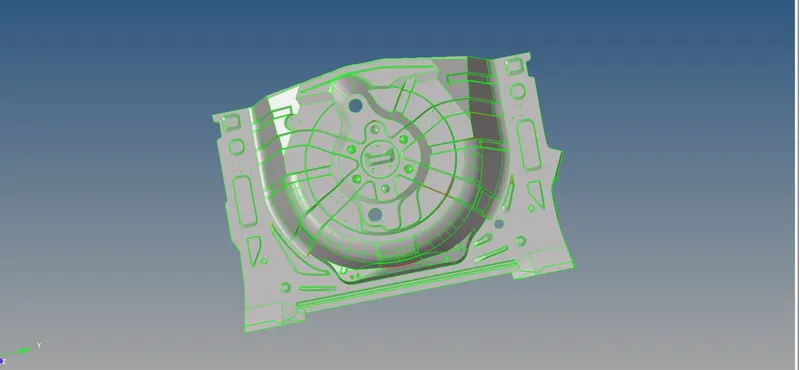
Now check for any geometrical error and repair it using quickedit,replace node,surface etc
Also try to be in Topo mode
and use wireframe mode to delete unneccessary points and lines which are not visible.
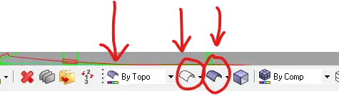
Some geometrical error fixing
To repair geometry there are lots of tools but in the quick edit panel there is many options to repair the geometry
To go to quick edit
First go to Geom-Quick edit

1. Toggle
It is the tool by which we can supress the lines and stitch the free edges
with this you can supress unneccessary lines which will give errors in meshing
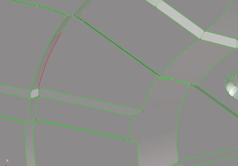
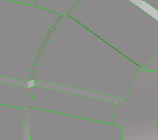
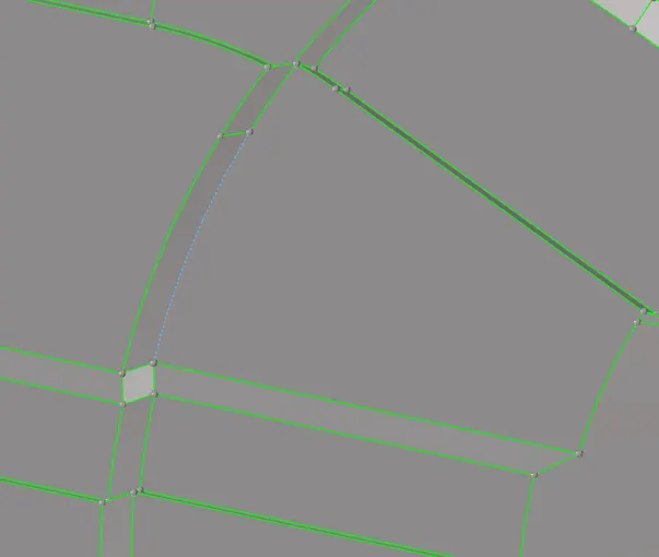
free edge(before toggle) After toggle you can supress it by click on line after toggling it
2.Delete which will cause problems in Meshing beacuse of small size
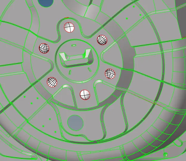
Delete this buttons
3.Mask and Delete
I have used Mask by using shortcut key F5

Delete option by using shortcut key F2.

Mask
It is used for hide things(surface,elements,etc) temporary
Delete
As the name suggest it deletes things (surface,elements,etc)
Now,lets see some errors i have solved using Mask and Delete
#Error
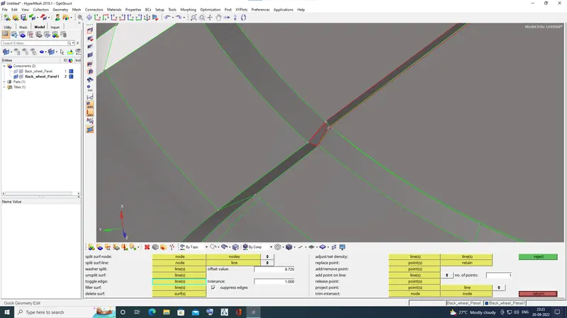 Before(fig 1)
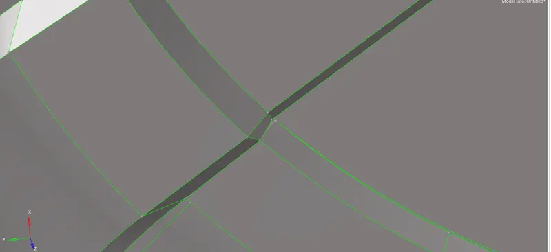 After(Fig 2)
Solution
To solve this ,I used mask option to see how many unnecessary surfaces are there
And then deleted the extra surface and made new using surface ruled option by going to Geom-surface-Ruled-select lines-then create.
Below are some Similar Errors
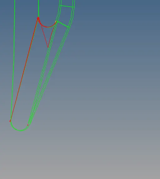
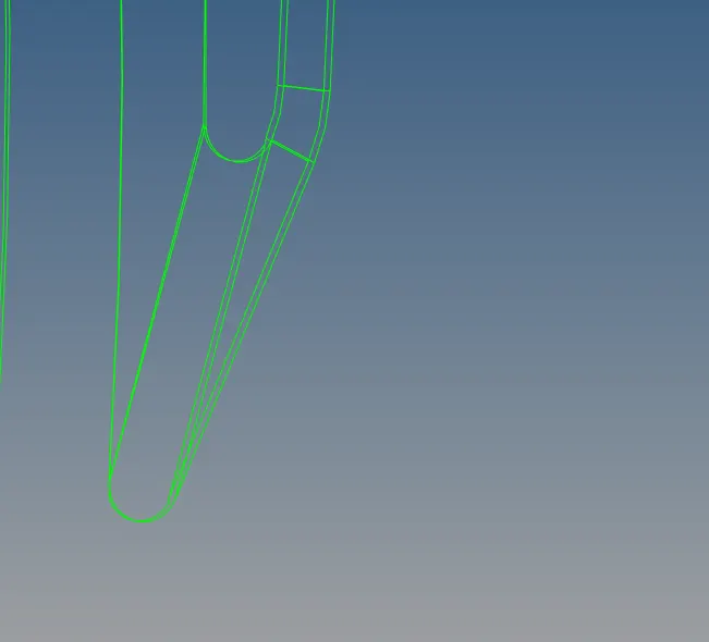
Before After
Sometimes there are just duplicate underneath surfaces so first mask upper surfaces and then delete.
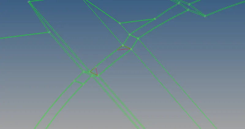
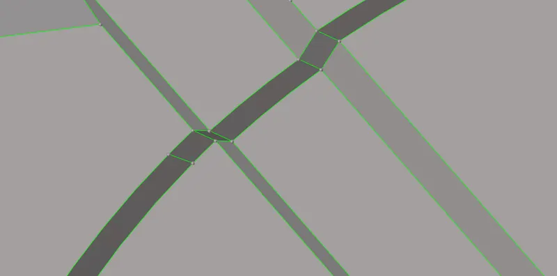
before(in wireframe) After
first mask the outer surface then delete the extra surface.
Remove unneccessary points after their use because they can interfere in meshing later.
By using add remove point in quick edit panel

Now,After cleaning the geometry
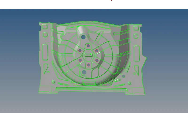
Split the surface (it is optional but very benefcial for complex geometries)
First , decide where do you want to split and assign temp nodes there by going to Geom-Temp nodes-
and then click on line and then click multiple times and then click on create and make another one on another end.
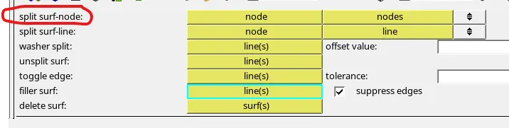
and now creating nodes use split surface node from quick edit
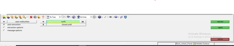
Now, Create mid surface
There are many Options to Create Mid -Surface
And,Here I am Using Auto extractiion by going to Geom-midsurface-Auto midsurface-Auto extraction
And then right click on surfs - displayed-then it will extract the mid-surface.
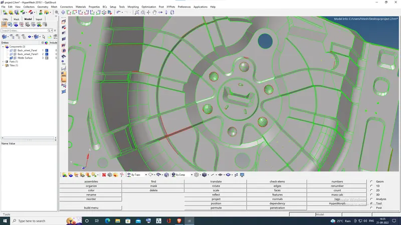
Extraction of Mid-surface is completed and there are some minor errors ,just stitch them using Toggle.
After cleaning the Mid-surface
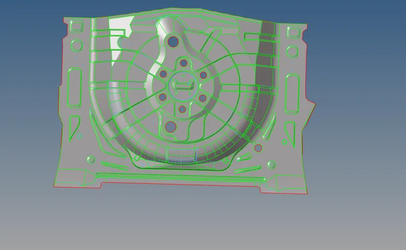
NOW,MOVE ON TO MESHING.
NOW first check the criteria file settings and match them with question.
by going to peference--criteria file settings
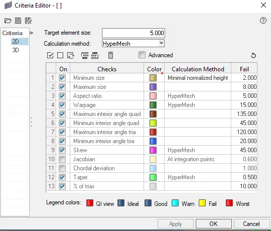
NOTE:do not mesh whole surface at one time and mesh separately using split surf node by going to quick edit option.
Now,go to 2D-Automesh-select the surface and select mixed and give the value 5 for target element size and then click on mesh.
Now,try to minimise the tri elements as much as possible
Things i have done to minimise the tria elements
Rebuild mesh multiple times by going to 2D-rebuild mesh

Go to quality index by going to 2D-quality index and check how many elements are failing and worse conditions and correct them using cleanup tools in quality index.

Use Replace node by shortcut F3

Use align option by clicking F7 key

clean elements by going to 2D-edit elements and
See if there is any coloured elements and clean by selecting the elements and click on clean.

#Remove unnecesaary points it makes mesh smooth
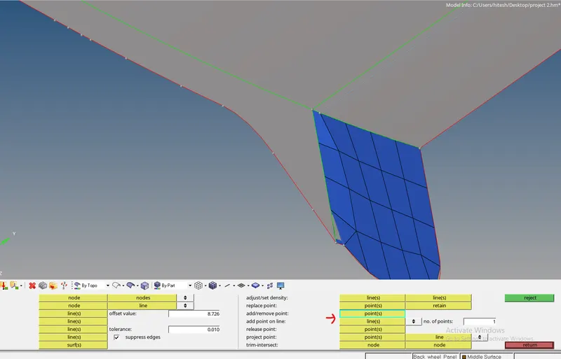
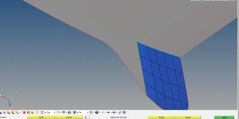
Before After
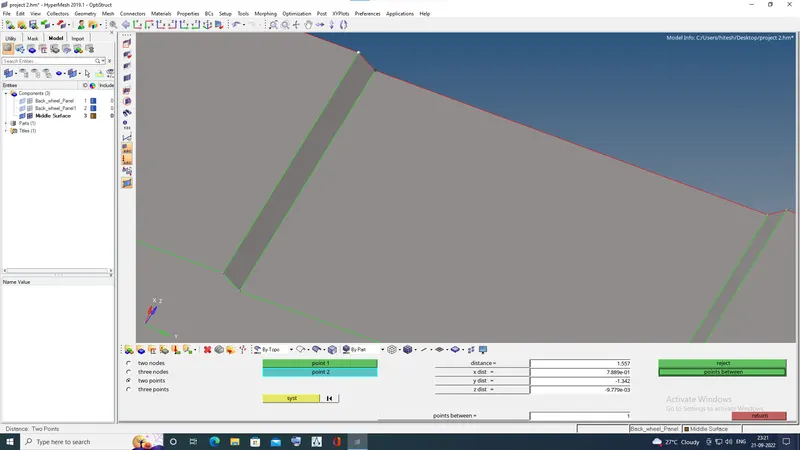
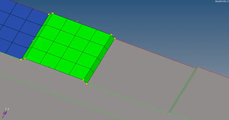
#I have to toggle one line because distance is smaller than element size
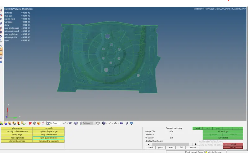
Final Mesh
#Now Assign Thickness
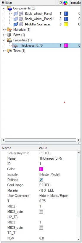
Before giving thickness first measure the thicknness of component from parent geometry.
To Assign thickness ,
create Property by right click and create property-then select property and new dialog box will appear
then give thickness and then after that assign it to all components.
#NOW THE MODEL IN 2D DETAILED ELEMENT REPRESENTATION

CONCLUSION
THE MESHING IS DONE.
ASSIGNED THE THICKNESS.