Week 12:Project 2-Meshing of Rear Wheel Holder challenge
MESHING OF REAR WHEEL HOLDER
AIM:-
To extract a mid surface and mesh the given component.
OBJECTIVES:-
1. To geometrically clean the model for any error on it.
2. To extract a mid-surface of the component.
3. To clean and defeature the Midsurface so as to avoid any minimum length errors while meshing.
4. To mesh the midsurface while trying to minimize the number of trias and its concentration.
5. Clear all elements that are failing any Quality criteria that was set.
6. To assign thickness to the mesh according the component.
7. Checking for free edges.
PROCEDURE:-
1) Import the Model -
This is the first step in any preprocessor tool, we have to import a cad model.
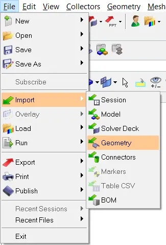
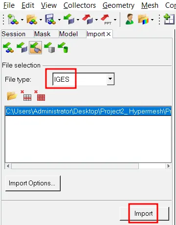
File > Import > Geometry > File type - IGES > Locate the .iges file > Open > Click on the file > Import
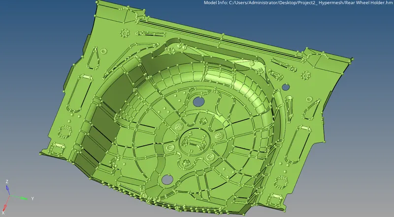
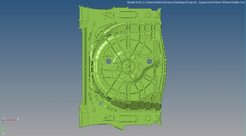
2) Geometry Clenup -
If any unnecessary triple cons, double cons, single cons, sharp corners, free edges etc. as a cae engineer we need to cleanup the geometry by manually using quick edit, edge edit, lines, and surfaces commands.
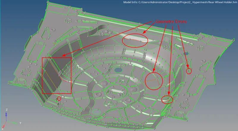
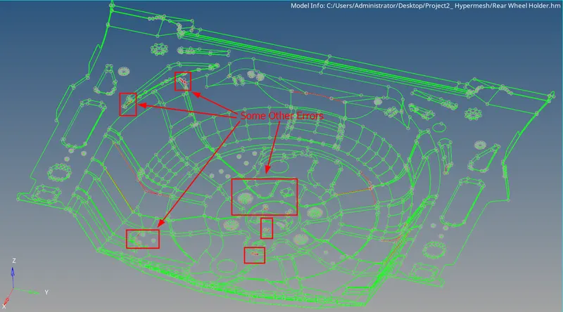
Sometimes these errors are not visible directly so we can swith to the wireframe mode in order to get a more clear and informative view regarding these errors and address them to get them fixed. Quick edit panel and surface panels have some of the most used commands for geometry cleanup.
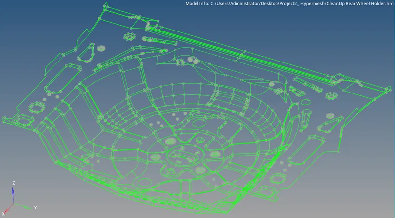
After Geometry Cleanup -
3) Thickness Measurement -
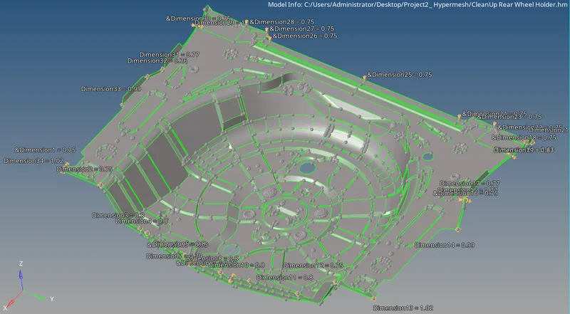
Thickness is measured at various regions of the geometry in order to figure out the average thickness of the component since it is plastic component with thickness variations and the average thickness is coming out to to be 0.83mm when evaluated.
4) MidSurface Generation -
This is the first step to take after completing the geometry cleanup. It is maily depending on component, we need to identify weather we are working with the sheet metal component, plastic trim, etc.
- If the thickness is greater than 5mm we will choose solid meshing.
- If the thickness is less than 5mm we will go for shell meshing.
- if the thickness might be uneven then also we will choose solid meshing.
here we are taking a mid surface by using mid surace command, we have different types of automidsurface methods in under this -
- skin offset
- offset
- sweep+planes
- offset+plane+sweeps.
Geom > midsurface > extraction options
by manually checking with different components with different algorithms then only will get which method is best suitable for which component. generally skin offset gives the better results while taking a mid suarface, sometimes offset command.

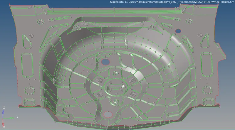
Here in this case we need to take midsurface manually by offset method because we are not getting proper midsurface using either of the methods mentioned above. we create a new component in which we will be having the midsurface and set it as current component.
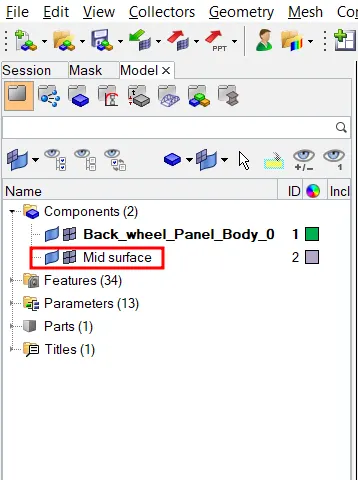
The offset distance is 0.83/2 = 0.415mm
Surface Edit(Shift+F9) > offset > Select the surface > surfs > duplicate > current comp > Enter offset distance - 0.415mm > offset
5) Quality Criteria Setup -
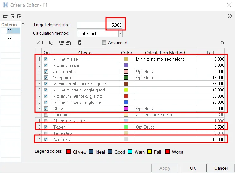
Before we can strat meshing, we need to set the Quality criteria for the meshing process. To do this, we need to use the Preferences tab and use the option of Criteria File Setting. In this option, we need to fill in all the necessary Quality criteria values such as the value of minimum and maximum length or and even the value for warpage etc. as shown in the image below.
6) Meshing -
After the Quality criteria is set, we then need to proceed to mesh the midusrface. To perform meshing on the component, we need to use the command of Automesh (F12) under the 2D Tab. In this command we need to change the element type to "Mixed" and change the average element length to 5mm (as given in the Quality criteria).

Always keep the flow Align and size option ticked as it will give a much better mesh flow on the component. The basic rules while meshing are to be followed here, such as that there should be no tria element on a feature line and even to avoid the rotational Quad elements in the mesh. We also need to keep the tria count as low as possible because Tria elements are much more stiffer than Quad Elements, but Tria elements are to be given preference over the presence of Rotational Quad Elements. If we get any Fixed/Pattern Tria we simply need to remesh these regions. Or we can simply resolve the Rotational Quad elements into two seperate tria elements in two different directions or even resolve the Fixed/pattern tria elements into three different directions as well.
For better mesh flow and control over the nodal number, we can divide the geometry into much smaller segments that can be meshed individually.
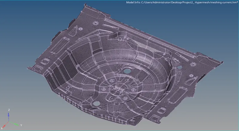
After meshing the entire mid surface, the meshed mid-surface looks like this -
7) Quality Checks -
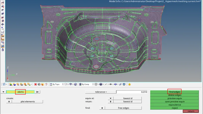
1. Free Edge Check - There should not be any free edge present in between elements other than at the boundary of the mid surface if it is present anywhere in between throughout the component then that means there are connectivity issues which is not acceptable so this needs to get resolved. Go to Tool > edges > elems - displayed > find edges to check for the free edges.
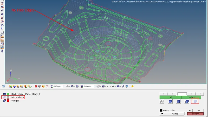
Hit x key to go to the visible attributes where we can decrease the transparency of the elements to clearly see the free edges as shown in the image below.
2. Connectivity Check - Go to Tool > edges > elems - displayed and check for different tolerance values by clicking on preview equiv and then click on equivalance to get the issue isolved if any.

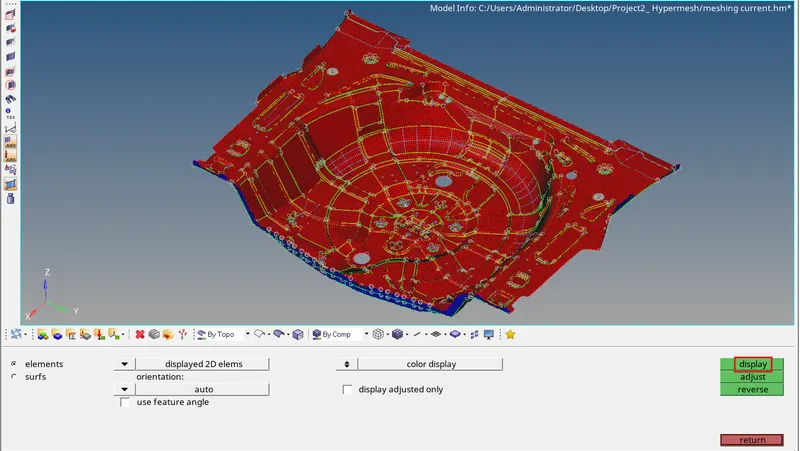
3. Normals Check - Normals should be checked after meshing the component, go to Tool > normals > display. whole face of one side should have red or blue colour click on adjust if not so.
8) Thickness and Property Assignment -
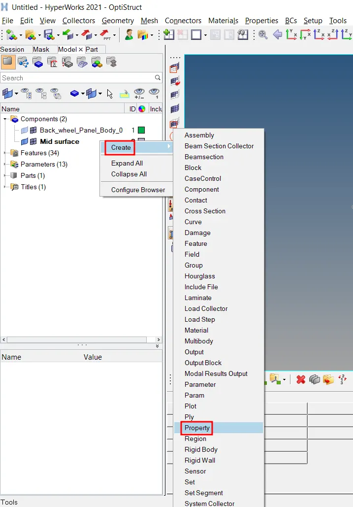
Now to assign proper thickness to the elements, we need to create properties and change the value of thickness for that property. To create a property, we again right click on the tree and select the create option and under this option we need to select the option of Property.
After we create the property, we then need to change the value of thickness for this property. The value of thickness for a property is under the value of "T" under the property tab. So if the thickness of the component is 0.83 mm, then we need to change the value of "T" to 0.83
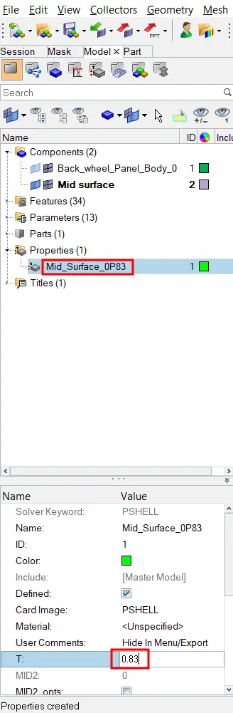
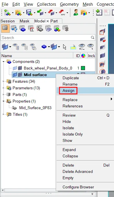
After the property is created, we then need to assign this property to the component for it to reflect onto the elements. To do this, we simply need to right click on the component and select the option of assign.
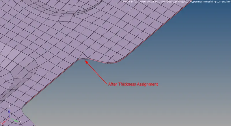
Now that the property is assigned, we can view the 3D elements with the thickness assigned by changing the view from "2D Traditional Element Representation" to "2D Traditional and Element Representation". The final Thickened mesh will look something as the following.
CONCLUSION:-
The given Rear-wheel holder panel has a consistent thickness, the mid surface was easily taken using offset option manualy. The model contains several sharp edges which were a major concern during the meshing process. warpage failure was the major issue which faced in the sharp edges. So those are eliminated by using the translate option. This model was a very complex model to capture features in detail.