Project-1-Meshing of Door Inner Panel (Plastic Trim)
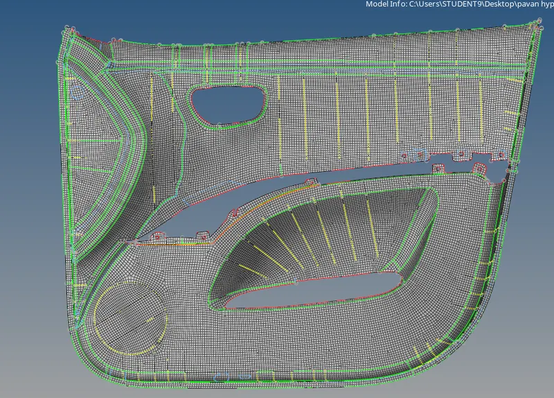
AIM: To perform shell meshing on an Automotive side door Interior plastic component with given quality parameters.
Quality Criteria:
Target Element Length = 4mm
| S.N | Quality Criteria | Value |
| 1 | Aspect Ratio | 5 |
| 2 | Skewness | 45 |
| 3 | Warping | 15 |
| 4 | Taper | 0.5 |
| 5 | Min. Length | 2mm |
| 6 | Max. Length | 6mm |
| 7 | Min angle Quad | 45 |
| 8 | Max angle Quad | 135 |
| 9 | Min angle Tria | 20 |
| 10 | Max angle Tria | 120 |
| 10 | Tria % | 10 |
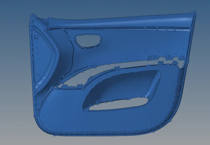
Given Component:
Theory:
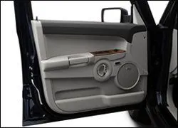
- An interior component attached to the inner side of the door. This product does more than merely improve the appearance of the vehicle interior. Rather, it is a vital module component that creates a more comfortable interior by providing a variety of accoutrements and functions.
- In that panel there are speakers and some electronic circuit wiring are present and there is a place to keep the personal things like water bottle, wallets etc.
There are various steps before going to the meshing procedure:
- Import the CAD model
- Geometry cleanup
- Mid surface extraction and assign the thickness
- Meshing process
Import the CAD model :
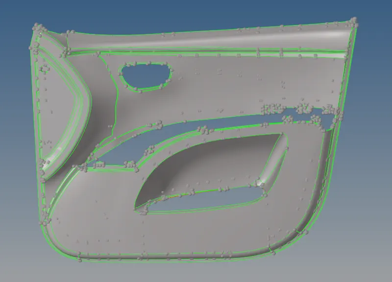
- First import the CAD model for that go>import model>then check that which format(IGES, STEP etc.)>then import.
Geometry cleanup:
- After importing the model put it on the topo mode and check the geometry is fine or not, If not we can first clear the geometry then move on to meshing.
- we can check the geometry using the check geometry under the toolbar when we click on it it will show the errors like unchecked faces, needle faces, shraps edges, triples, single cons etc.
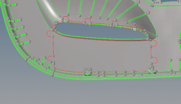
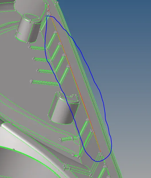
- For Clearing the geometry we should use the required options like geometry>Qucik edit shown in below image.

Mid surface extraction:
Midsurface modelling is a technique for creating a simplified shell representation of a solid model. Midsurface modelling can reduce the computational expense of analyzing a complete solid model when a shell model with a defined thickness and fewer details is suitable for the required analysis.

- We should extract the midsurface for the whole component, first, go through the individual component then extract the midsurface for that go to midsurface>auto midsurface>use Extraction options as per our requirement.
- If it not coming properly, use different options to obtain the better mid surface.
- After extracting give original thickness to the elements for that goto>property>thickness>then that property is assigned to the components.
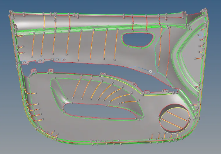
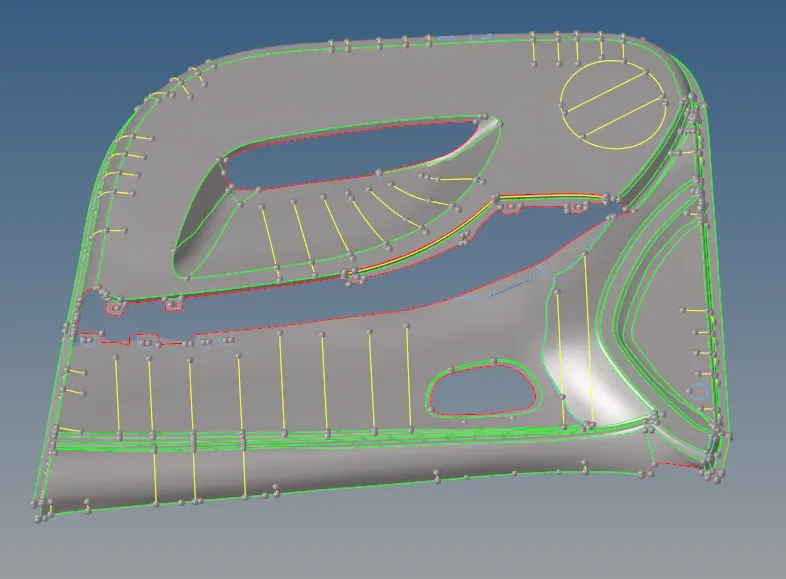
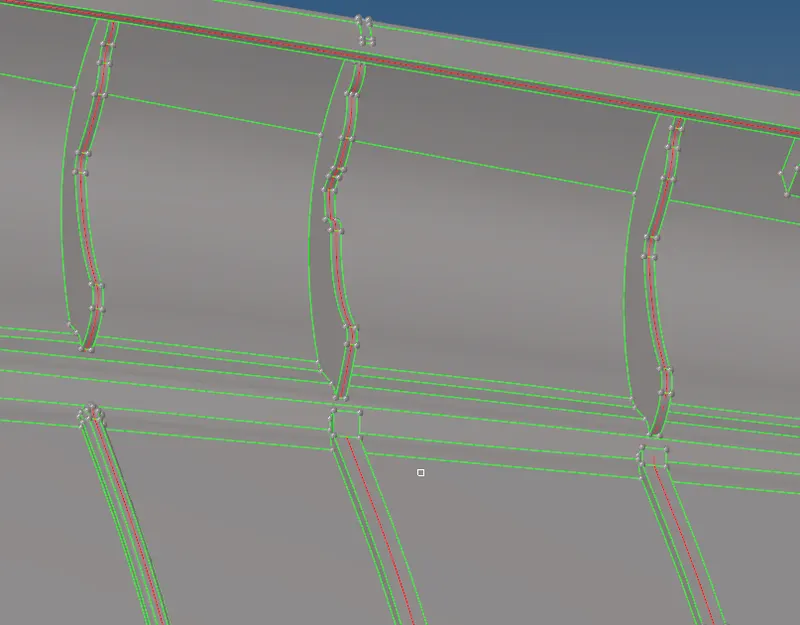
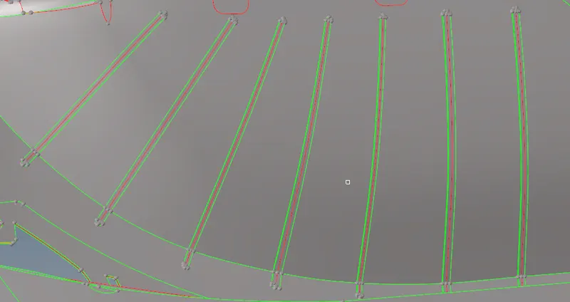
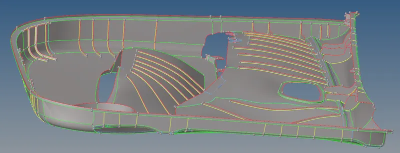
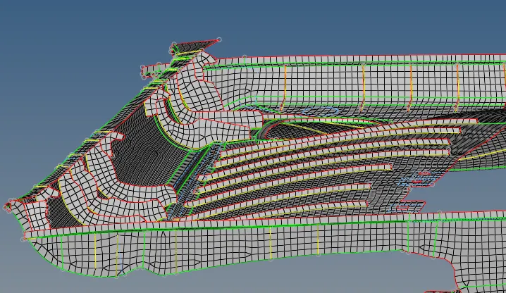
- In this plastic trim, the main change is the extraction of midsurface for ribs and attaching to the base surface as shown in the below images.
Defeaturing:
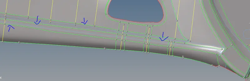
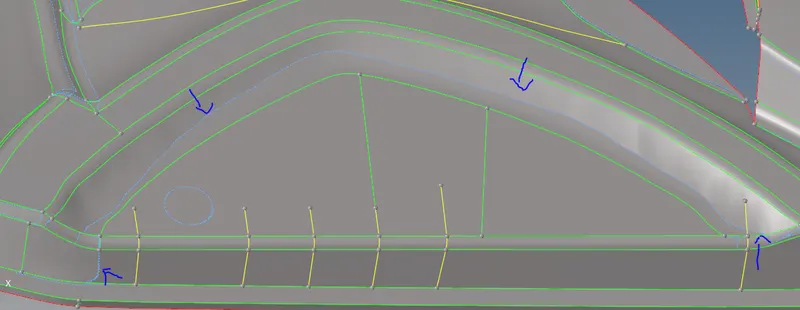
Defeaturing is the removal of details in the geometry in order to make the shape of the part simpler. Surface fillet, Pinholes, Edge fillets or we have to compromise on the one feature to save another feature.
Meshing:
A mesh is a network that is formed of cells and points it can have almost any shape in any size and is used to solve partial differential equations. each cell of the mesh represents an individual solution of the equation when combined for the whole network results in a solution for the entire mesh.
Meshing is an integral part of the engineering simulation process where complex geometries are divided into simple elements that can be used as discrete local approximations of the larger domain. The mesh influences the accuracy, convergence and speed of the simulation.
- First, we have to start from one side which as the low concentration area and then move to the high concentration area with having the minimum amount of trias.
- We can create a new construction line perpendicularly in some area which we can define the area to get the better mesh to flow over there. In the fillet area, we can compromise on the trias because in that area we avoid those trias over there.
- Then we can go with the best mesh option in mesh generation box, the mesh is done by area by area to get good mesh if any quality issues are coming we can go with the reconstruction option and after reconstruction us the smooth option to smooth the mesh.
- We can remove the trias using the rebuild, move node option and swap option to element the trias and make sure that there no tria elements in the edges of the component we can swap the trias using the swap option.
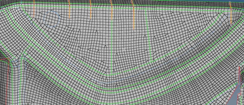
More tria concentration areas:
- This can be avoided by the again auto mesh option or rebuild option.
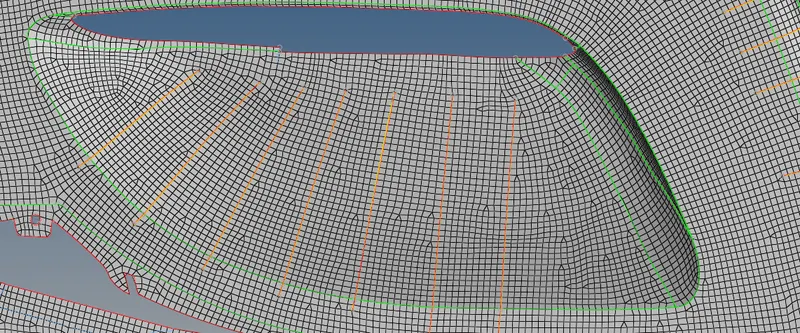
Meshing on Ribs area:
- Here we have to concentrate on the mesh connectivity issues this can be avoided by using the advanced remesh option before going to the mesh.
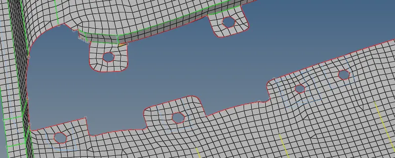
Meshing on the area of the holes:
- If there are small holes we have to mesh as itis or if there is a big hole having large diameter we have to define the washer split over there because in the region of the hole there is the high-stress concentration.
Meshing on edges of the component:
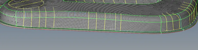
- Here in edges, we have to maintain the proper mesh flow with a minimal amount of trias
CONCLUSION:
The given Automotive side door Interior plastic component has meshed with mixed elements of trias and quads with the given quality criteria.
Learning outcomes:
- In this challenge, I am able to understand how to obtain better mesh flow over some critical areas on fillets and also eliminating the trias by using the split, swap, rebuild options.
- In was able to understand the doing the midsurface of a component using both auto midsurfacing and manual midsurfacing with options midsurface and offset.
- I have got an idea about the side door plastic trim and how to perform a better mesh flow over the plastic components components.