Week 12:Project-1-Meshing of Door Inner Panel Challenge
Objective:
Create the midsurface and cleanup the surface. Mesh the extracted midsurface and assign thickness to each and every features.
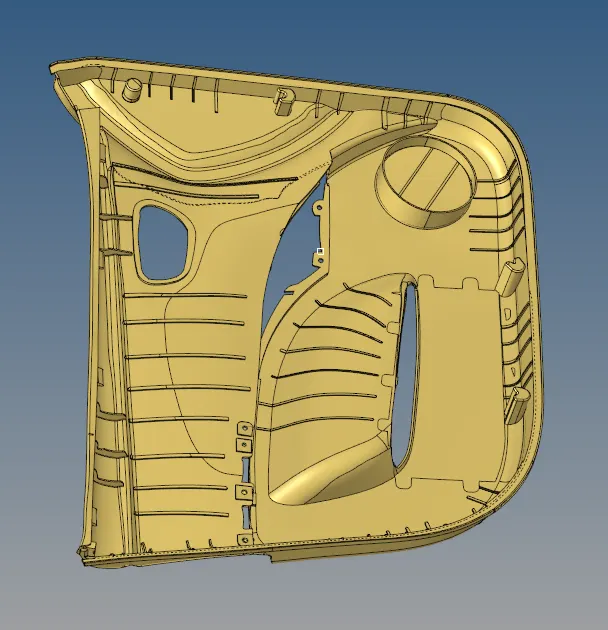
Procedure:
Midsurface:
The above given CAD model has various different kind of features involved with different thickness assigned to each features.
Initially the surface which has less or features appeared on is chosen. Using offset option midsurface is extracted.
geometry-> Surface edits-> offset-> choose surface-> Duplicate-> set distance.
The above steps are involved to offset the surface to the desired distance. Here the base surface has thickness of 2.8 units. Therefore the selected surface is offsetted to 1.4units of distance.
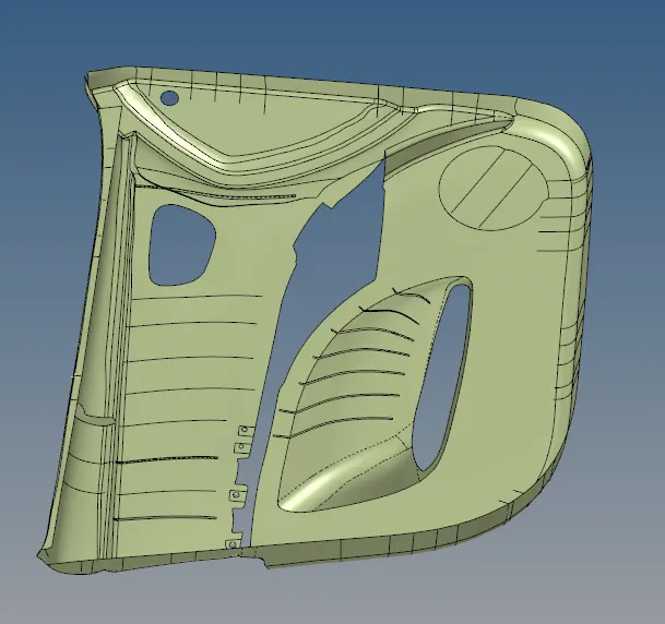
In the above extracted midsurface the further features involved in the CAD model is extracted using either midsurface tool or offset tool.
Easy extraction components are extracted using midsurface tool whereas complicated features are extracted manually using offset tool as mentioned aboe.
Also in auto extraction of midsurface various methods are involved. The most often method used to extract midsurface for the given CAD model is mentioned below.
Geometry-> midsurface-> final edit tools-> Side1; Side2 -> Extract.

Before meshing the surfaces, the various different surfaces are to be connected or to stitch the surfaces into single surface.
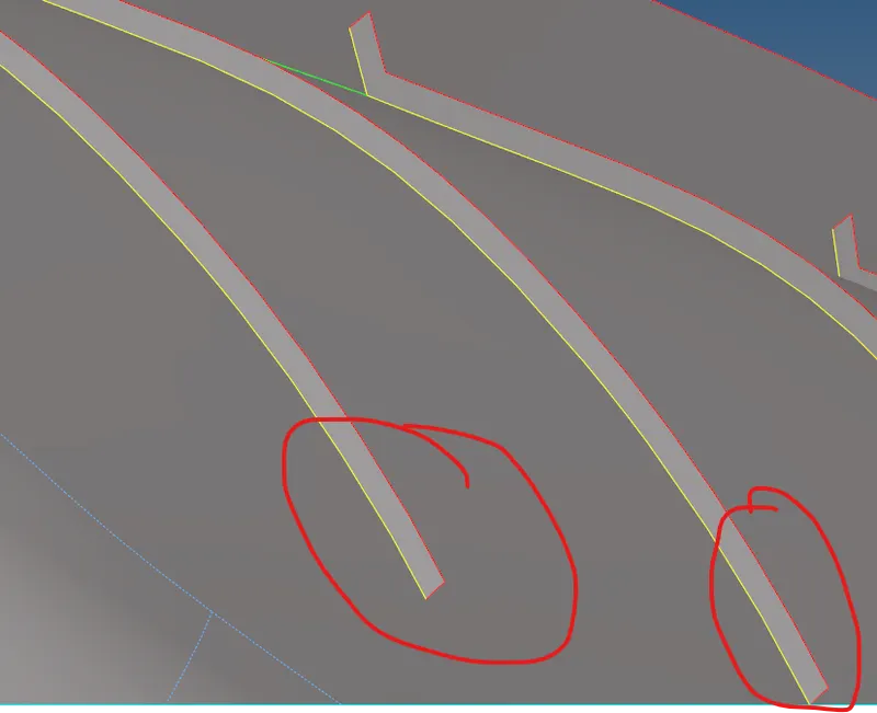
THe yellow line indicates that the two different surface edges are stitched together.
To stitch the surface extend tool is used.
Geometry-> Surface edits-> Extend.
Select the surface to be extended and target surface.
Press extend to stitch them.
Meshing:
Meshing is straight forward as followed before. Select the midsurface extracted and automesh tool is used to create elements.
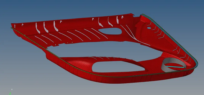
Every feature is selected and mesh is done.
Thickness Assigned:
Each feature has their own different thickness. To assign thickness to all features each feature of same thickness are gathered in a individual collector. And all the collectors are assigned with different thickness with property component.\
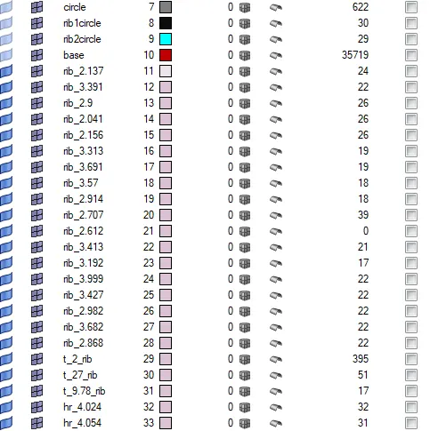
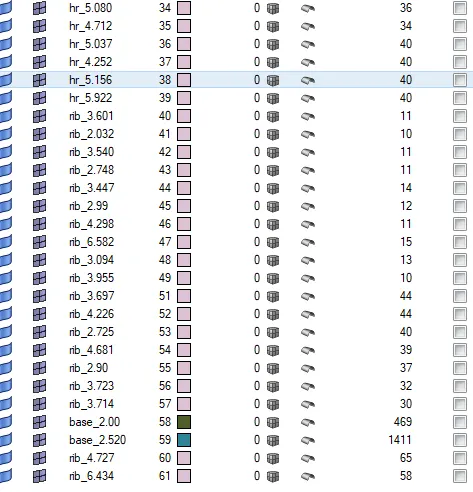
The above listed are the components of different thickness values.
According to their thickness values, each components are collected in the separate collectors.
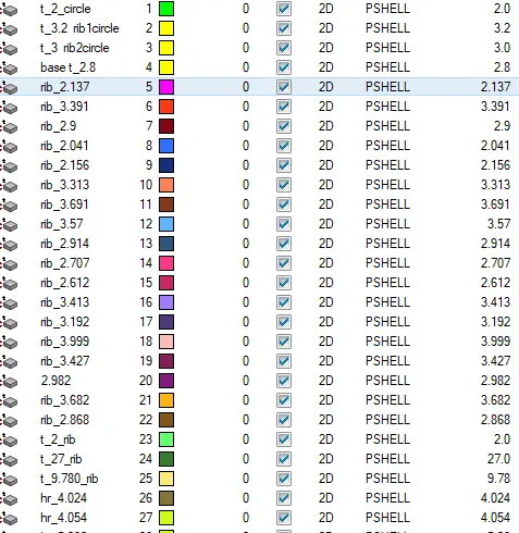
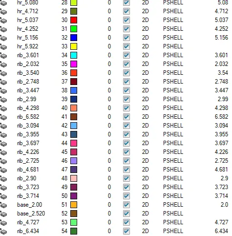
Similarly the property component is created for each different thickness components with their respective thickness.
These properties are assigned to their respective components using the following steps.
Right click on component-> Assign-> choose respective property.
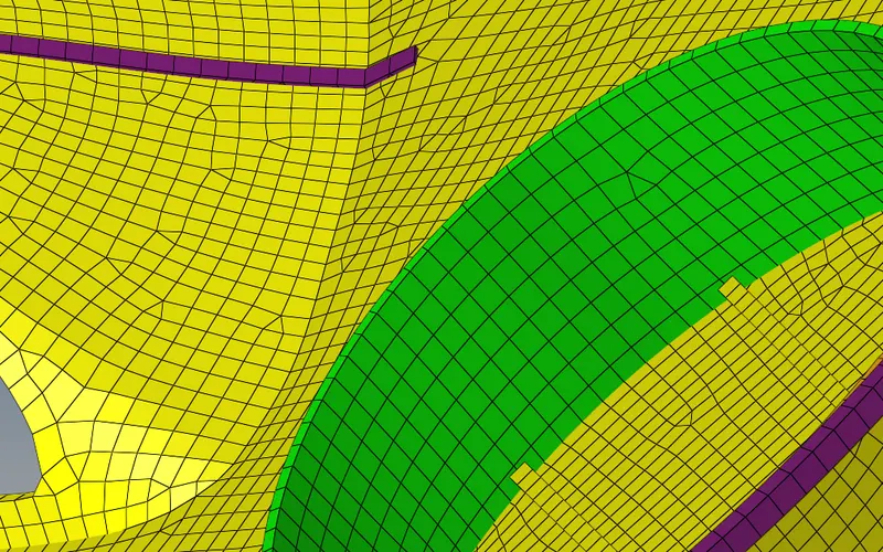
It's seen that each component is assigned with different thickness.
Result:
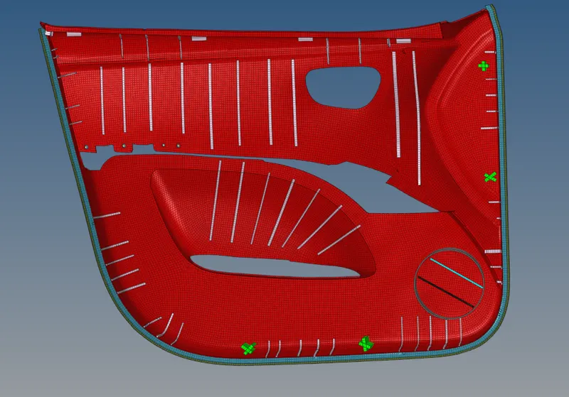
Thus the given CAD model is used to create midsurface and to mesh the midsurface with the given thickness value.