Week 12:Project-1-Meshing of Door Inner Panel Challenge
PROJECT-1
MANUAL MIDSURFACE EXTRACTION: When working with plastic components, the mid-surface must be manually extracted because the thickness is not uniform. Some parts of the component may be x thickness, while others may be y thickness. As a result, we must manually extract mid-surface using the techniques listed below:
Make a new component with the name mid-surface Txx.
Measure the component's thickness and use that instead of xx.
Make it a working part.
Select surface-edit offset from the drop-down menu.
Choose the surface that we believe should be the part's mid-surface.
Duplicate the surface in the current component by clicking on it.
To get the mid surface of that feature, enter the offset value, check the normal, and offset the surface.
Every feature must go through a similar procedure.
Create a new component called mid-surface Txx.
Instead of xx, measure the thickness of the component.
Make it a functional component.
From the drop-down menu, choose surface-edit offset.
Select the mid-surface of the part that we believe should be used.
By clicking on the surface in the current component, you can duplicate it.
Enter the offset value, check the normal, then offset the surface to get the feature's mid surface.
Every feature has to go through the same process.
When establishing a mid-surface component, give it the name mid-surface Txx, where xx is the part's thickness.
This should be done for each feature in the model.
Create the property with a right-click and the name Txx.
Assign the property a thickness of xx.
Assign the property to the component's thickness by clicking on the component's mid surface.
THE MID-SURFACE IS EXTRACTED: The surfaces are connected as they were in the parent geometry after the mid-surface is extracted. To sew them together, follow the procedures below:
Go to Geom's surface modify and extend section.
Select extend over edges and by distance from the drop-down menu, then enter a random distance number.
Extend both surfaces that will be linked.
Trim using surfaces/planes in Surface edit
Check the trim together option after selecting the surfaces to be trimmed.
Remove the unnecessary surfaces.
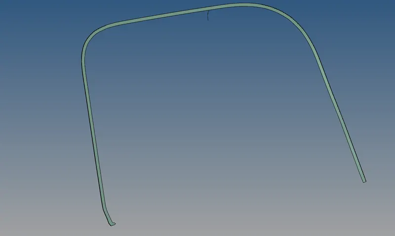
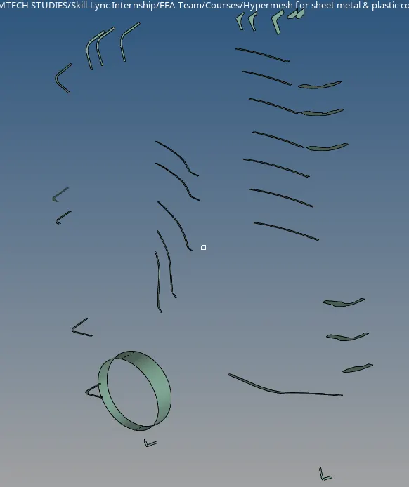
STEP-2: Manually Extracting the Mid-Surface: The procedure of manually extracting the mid-surface as described previously. To get the mid surface, repeat the procedure. The steps I took to remove the mid-surface are listed below.
Manually extract the component's major mid-surface
Manually remove each comp's mid-surface.
Geometry Clean-up is the most important step in the meshing process because it determines the mesh's quality. A good clean-up can result in a high-quality mesh, whereas a poor clean-up can result in a mesh that will require a lot of refinement. The cleanup procedure should include the following phases.
Flange and main mid-surface should be combined.
Combine the primary mid-surface with comp and other characteristics.
Remove minor fillets that may cause the elements to fail the minimal element criteria by using the defeature option.
To suppress unwanted edges, use rapid edit panel features like toggling edges.
Trim the geometry as needed, primarily to create a square and rectangular shapes.
To merge nearby points, use the replace points options.
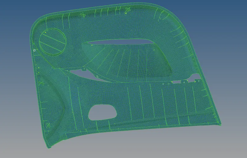
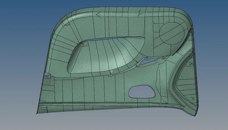
After tidying up the geometry, we must mesh the component and confirm that all of the pieces are in good working order. By selecting all of the surfaces at the same time, we can generate a mesh in one step. Follow the steps below to gain proper control over the mesh flow.
Because the component was divided into several little surfaces during the clean-up process, I preferred to mesh them one by one.
Create a mesh by going to auto mesh and selecting surface and element length as 4 units.
Reduce the number of tria elements by manipulating the nodes.
Set the parameter for the quality index and verify if any elements are failing. Use an element optimization tool or remesh the elements in such circumstances.
In some circumstances, we will need to split, merge, delete, and create elements.
In some circumstances, the nodes must be projected onto a line or a surface.
When all of the pieces are in good working order and the flow is consistent, we go on to the next section of the surface and repeat the process.
Rep this process until our entire component is properly mated.
Finally, give each feature of the component the appropriate thickness.
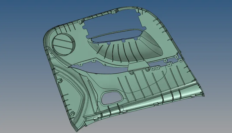
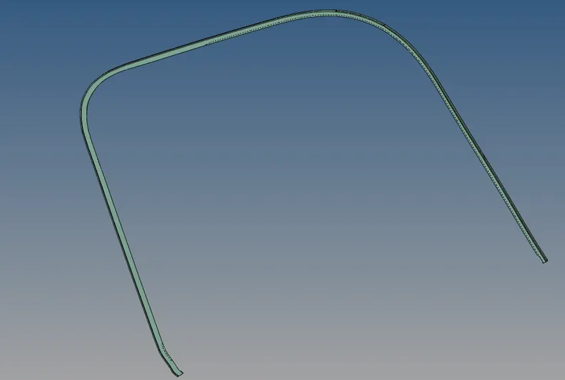
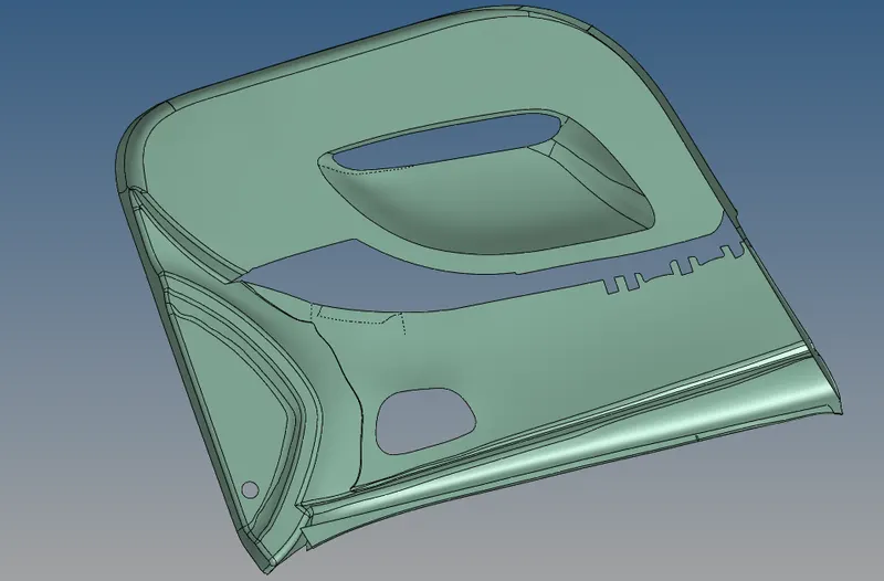
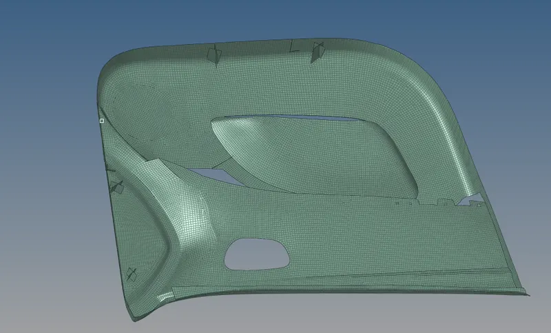
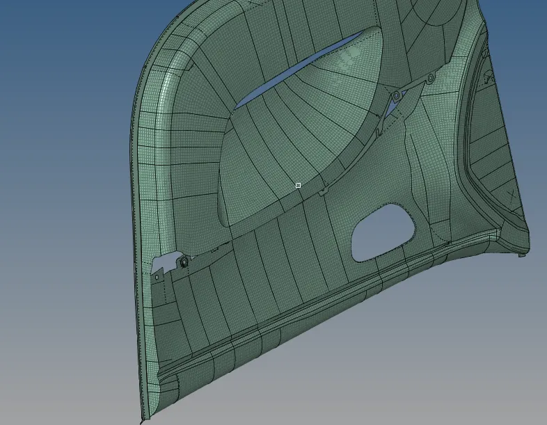
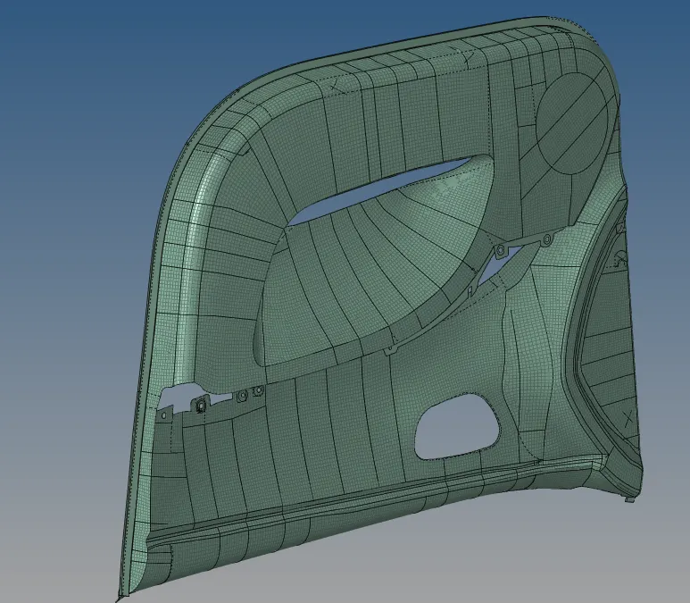
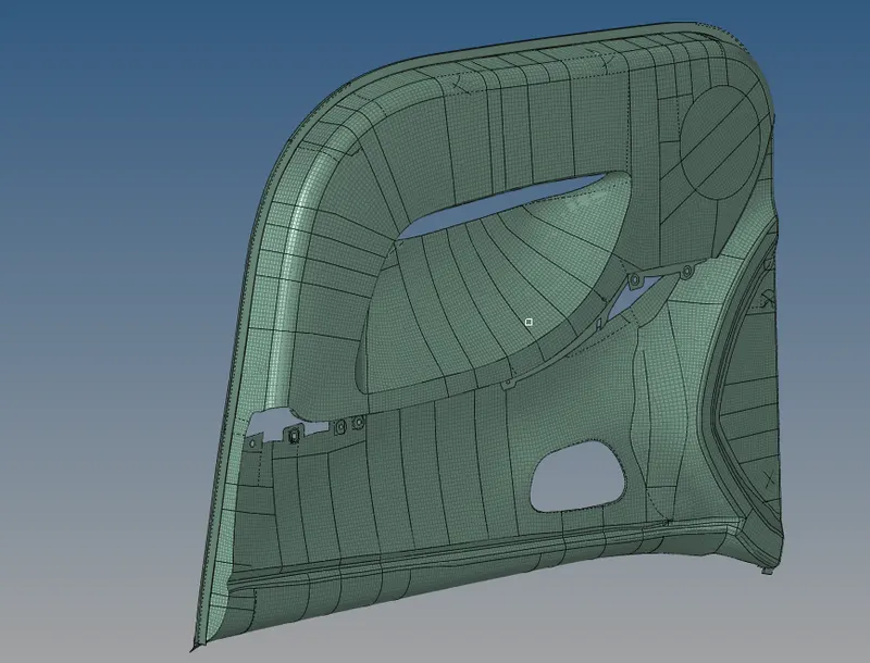
CONCLUSION: We learned how to mesh the plastic component utilizing manual mid-surfacing and assign varied thicknesses to different features of the same component in this assignment.