Week 12:Project-1-Meshing of Door Inner Panel Challenge
Aim : To perform Meshing of a Door Inner Panel ,with given mesh parameter and to extract the given side door.
Objective : to mesh the given side door model as given in above mesh creteria ,and to perform extraction of model .
* Given model :
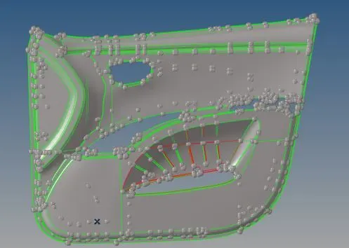
* Opening the model
* Click to open model as shown below

* After Opening the click auto clean up in geometry tab as shown below
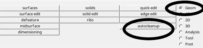
* Extracting the file manullay
* Making the model into smaller parts so that ,it can be worked easily .
*Click surface edit keeping it in geomrty and select trim with lines ,finally separate the model as shown below


* Select the required surface which need to be trimed and click ok
* The model before trimed are shown below
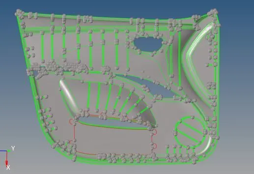
*The model after trimed are shown below
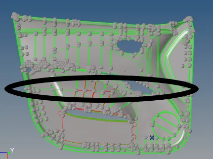
* As shown in above the encircled region are trimed into parts .
* Offsetting the trimed model
* Keeping a part in the model and measure the thickness of that part
* click to geometry and select distance ,moreover keeping in two points measure the thickness as shown below


* Click geomerty and select surface edit to offset the model after mesuring the distance
* keep in offset after opening the surafce ,enter the distance which need to be offste and select the surface
*click the offset as shown below


* The model which has trimed part are shown below .
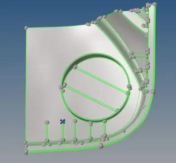
* The model which has offsetted are shown below

* Meshing the model :
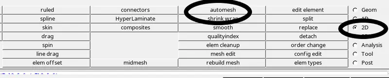
* Click 2D and select automesh ,giving the target element length as 4
* Selct the surface which need to be mesh and click mesh as shown below
* Performing mesh error
* In task bar click prefrence and select creteria setting ,apply the quality creteria which is given above and check the mesh errors
* By keeping it in 2d click quality index to check the mesh errors are shown below :


* The below shown are some options for cleaning the mesh errors

* Model before mesh errors
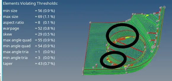
* The encircled region are the errors which need to cleaned
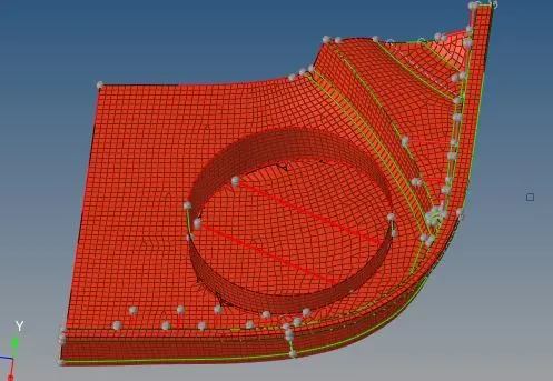
* Model after mesh errors
* Assigning the thickness to the offsetted model :
* In Model bar Rightclick the mouse and create a material of steel
* Same as create a property which need to assign a thickness ,the material and property are shown below
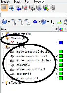
* Click to the component and below will get a menu assign the thickness
* Assign the property and material by clicking on it .
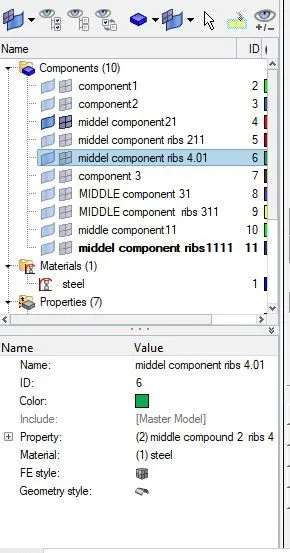
* Further from property assign the thickness of each and every model as shown below
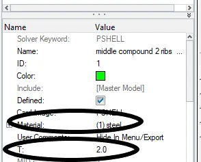
* The assigned thickness are shown below according to the model thickness
* Continue to each and every part of a model
* For Next part of the model
* Offsetting the trimed model
* Keeping a part in the model and measure the thickness of that part
* click to geometry and select distance ,moreover keeping in two points measure the thickness as shown below
* Click geomerty and select surface edit to offset the model after mesuring the distance
* keep in offset after opening the surafce ,enter the distance which need to be offste and select the surface
*click the offset as shown below
* The model which has trimed part are shown below
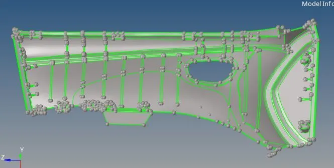
* The model which has offsetted are shown below
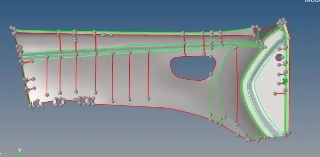
* Meshin the model :
* Click 2D and select automesh ,giving the target element length as 4
* Selct the surface which need to be mesh and click mesh as shown below
* Performing mesh error
* In task bar click prefrence and select creteria setting ,apply the quality creteria which is given above and check the mesh errors
* By keeping it in 2d click quality index to check the mesh errors are shown below :
* The below shown are some options for cleaning the mesh errors
* Model before mesh errors
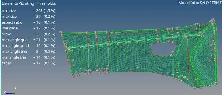
* The encircled region are the errors which need to cleaned
* Model after mesh errors
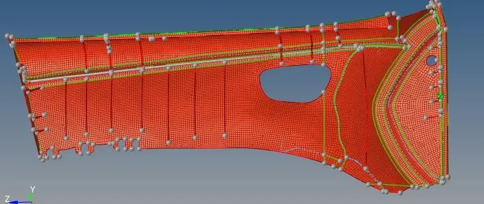
* Assigning the thickness to the offsetted model :
* In Model bar Rightclick the mouse and create a material of steel
* Same as create a property which need to assign a thickness ,the material and property are shown below
* Click to the component and below will get a menu assign the thickness
* Assign the property and material by clicking on it .
* The assigned thickness are shown below according to the model thickness
* Continue to each and every part of a model
* Further from property assign the thickness of each and every model as shown below
* For Next part of the model
* Offsetting the trimed model
* Keeping a part in the model and measure the thickness of that part
* click to geometry and select distance ,moreover keeping in two points measure the thickness as shown below
* Click geomerty and select surface edit to offset the model after mesuring the distance
* keep in offset after opening the surafce ,enter the distance which need to be offste and select the surface
*click the offset as shown below
* The model which has trimed part are shown below
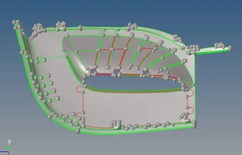
* The model which has offsetted are shown below
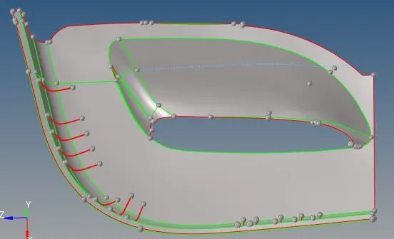
* Meshin the model :
* Click 2D and select automesh ,giving the target element length as 4
* Selct the surface which need to be mesh and click mesh as shown below
* Performing mesh error
* In task bar click prefrence and select creteria setting ,apply the quality creteria which is given above and check the mesh errors
* By keeping it in 2d click quality index to check the mesh errors are shown below :
* The below shown are some options for cleaning the mesh errors
* Model before mesh errors
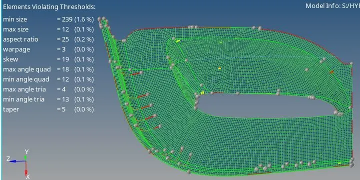
* The encircled region are the errors which need to cleaned
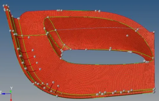
* Model after mesh errors
* Assigning the thickness to the offsetted model :
* In Model bar Rightclick the mouse and create a material of steel
* Same as create a property which need to assign a thickness ,the material and property are shown below
* Click to the component and below will get a menu assign the thickness
* Assign the property and material by clicking on it .
* The assigned thickness are shown below according to the model thickness
* Continue to each and every part of a model
* Further from property assign the thickness of each and every model as shown below
* Model after completion of meshing ,assigning thickness and offsetting are shown below :
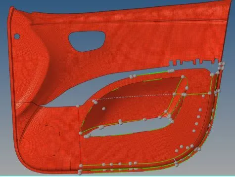
Conclusion : The given model can be worked for meshing ,assigning thickness and offsetting for given mesh creteria for the given model .The worked model are uploaded below