Week 12:Project-1-Meshing of Door Inner Panel Challenge
Aim
To extract mid surface and mesh with given quality criteria for side inner door of a car and assign thickness on it.
Introduction
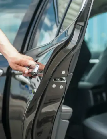
Door panel serve as an interface between the interior of the car and the inner working of the door. They are expected to meet a variety of design specifications regarding safety and functionality, other components attached are speaker, electronic window, a central locking system.
Procedure
Step1: Import the geometry
Import the given Geometry file into hypermesh, open HyperMesh software go to file -> import-> select the model.
Step 2 Splitting the grometry and defeaturing & Measurement
- Splitting the grometry
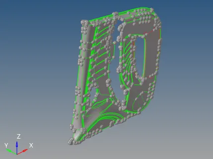
As we see the inner panel include many ribs and attachment components and small feature, such small feature increase the complexity in obtaining mid surface and also there are some features with varing thickness and some feature with no thickness. Splitting the geometry is done for easy extraction of mid surface.
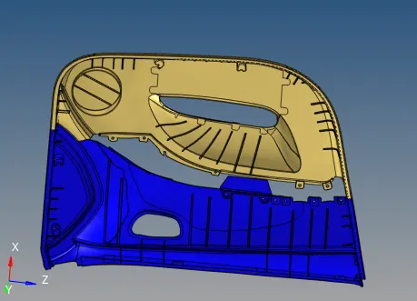
fig: Splliting the model.
- Defeaturing
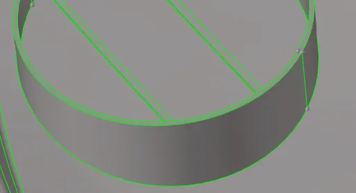
The geometry consists of many ribs with fillets less than our minimum elements length size, so defeaturing the filleta must be done to eliminate the elements failure size in these area. used defeature tool to defeature the ribs and pthere area.
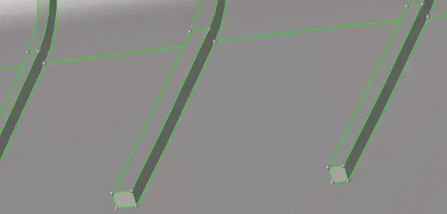
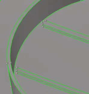
fig: Defearturing the ribs
- Measurement
To check thickness at different location on the model in order to assign the uniform thickness property of the model.
Step3: Mid surface extraction
The primary stage of meshing any part is to clean the geometry. when part are created in the CAD Modeling software and then open in the CAE software there are chance that the geometry get geometry error because of change in formatof the file.
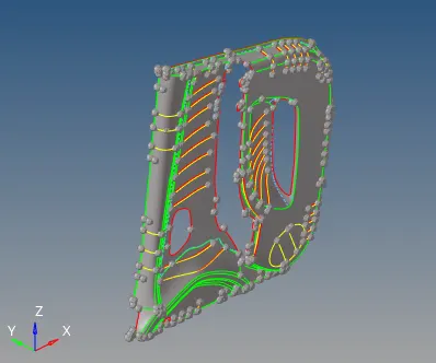
fig: Outer side of the inner panel
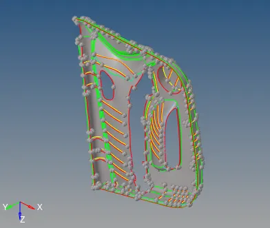
fig: Inner side of inner panel
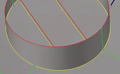
Step4: Assigning Quality criteria
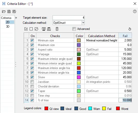
Meshing with 2D elements is basically performed using either tria or Mixed(tria and Quad). The accuracy of the result is depend on quality of elements. The quality criteria of the elements as shown below.
Step5: Meshing/Discretization
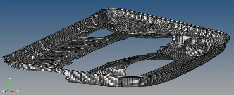
After assigning quality criteria, its time to mesh the model. for discretizing the model there are automesh command in 2D panel, by using this tool to mesh the model will mesh. for better mesh flow and reducing tria concentraction rebuilt tool is also used. Moreover elements clean up tool are used for better mesh flow.
Step6: Assigning thickness
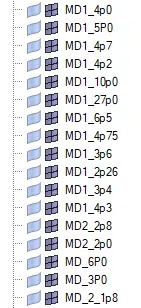
Many feature of the model had uniform thickness and some with non uniform thickess, for those with varying thickness different property card is assigned.
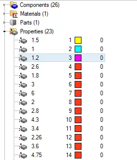
Step7: Elements checks
- Elem check
To check the elements quality criteria
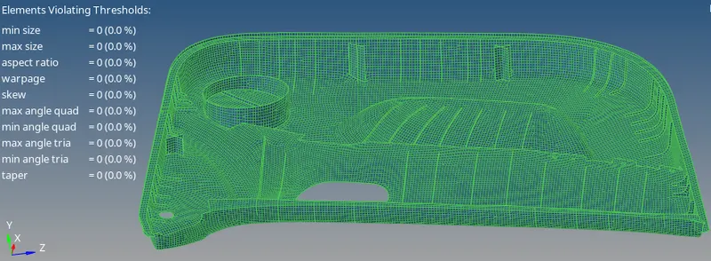
- EDGES check
Edges check is done to insure the connectivity of the elements is present.
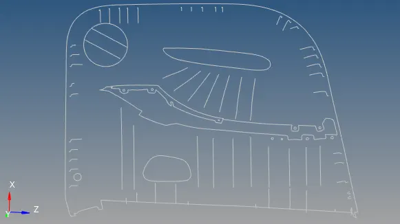
- Normal check
Normal check is perform to check the direction of the vector consistency of the geometry/Elements which directly affect the calculation of the physical quanity.
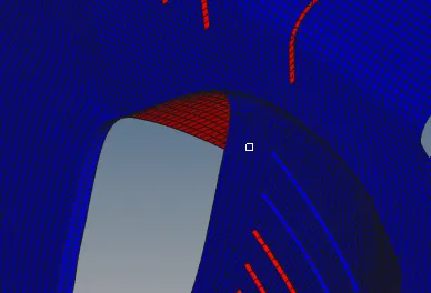
- Duplicate check
To check any duplicate elements are present in the model.
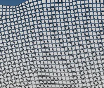
Final model
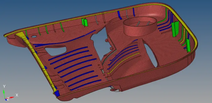
fig: with thickness
Learning outcomes
Able to understand
- Geometry clean up
- Defeaturing
- Assigning thickness
- Mid surfacing
- Shell/2D meshing
- Elements clean up tools
- Mesh flow
Conclusion
Geometry clean up, mid surfacing and Shell mesh was generated on the side door components with satisfying all the mentioned elements criteria.