Side door midsurface extraction and meshing
OBJECTIVE - To extract the midsurface of the given plastic component (Side door) and mesh the model acc. to given quality criteria and assign the thickness.
PROCEDURE - In order to accomplish the above objective we need to follow following steps.
1. Import the CAD model into hypermesh.
2. Geometry cleanup of the model.
3. Extraction of midsurface using manual various techniques.
4. Perform the 2D mesh on the midsurface.
5. Eliminate the failure element as per given quality criteria.
6. Assign the thickness to model and convert shell element into solid elements.
1. Import the CAD model into hypermesh - First we import the CAD file into hypermesh by using import geometry in menu bar.
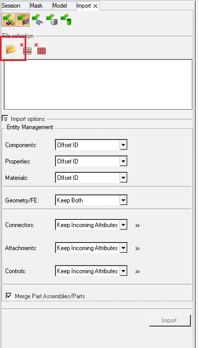
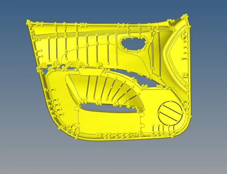
Fig . imported model
2. Geometry cleanup of the model - In order to extract the midsurface we make sure that the CAD model imported is free from topological errors like, free edges, crack , missing surface , duplicate surface or any deformation occurs in surface while importing the file into hypermesh . if any such errors are presesnt then eliminate those error in the model . Also remove the surface fillet in rib or parent surface in order to capture the feature properly in midsurface . for removing fillet goes into geometry > Defeature > surf fillet > find fillet in selected and choose the surface and give min. value 0.1 and max. value 15 and then find and surface fillet got selected and remove them.
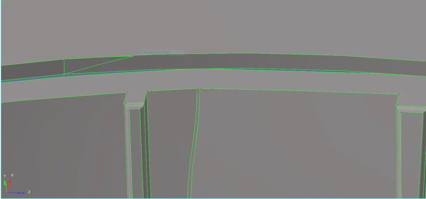
Fig. missing surface

fig. Defeature pannel
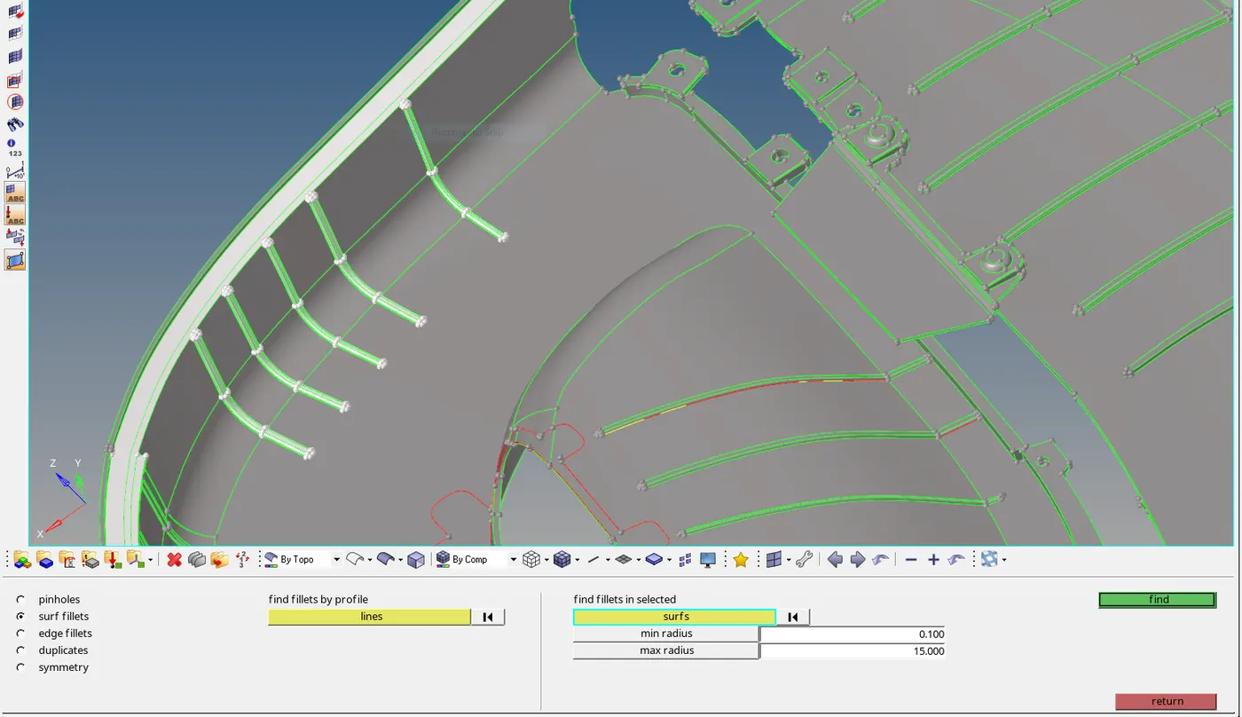
fig. Surface fillet pannel
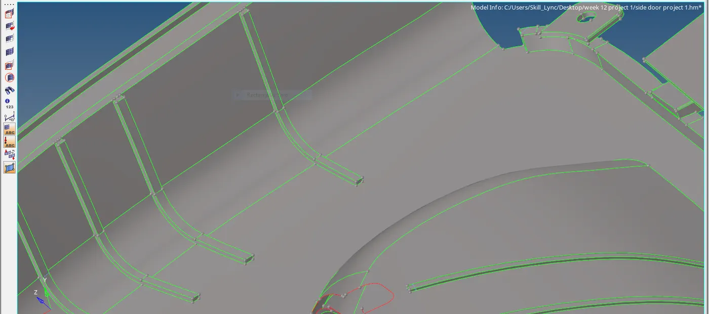
fig. removal of surface fillet
3. Extraction of midsurface using manual various techniques - Now the given plastic component is free from topological errors , now we can proceed to extract the midsurface of the component. first we extract the midsurface using auto extraction method.
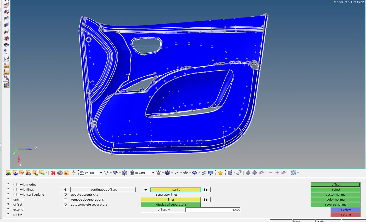
Fig. Offset taken of base model for midsurface
so in midsurface by auto extraction method there are some surfaces gets overlapped and some surface get distorted and missing due to the complexity of the model so now we delete the midsurface and create a midsurface by manual techniques. now we use a offset option to get a midsurface for that first we measure the thickness of each component , its a plastic component so thickness is varying in each part. first we offset a base surface which is 2.8 mm thick . press shift + F9 or go to surface edit > offset > Continuous offset > select as surface > duplicate the surface > give offset value (half of 2.8 ) > choose vector direction > offset. For extract a midsurface of rib we also used offset option and for linear rib we also used another command which is in Midsurface > final edit tools > select both side of surface > extract.
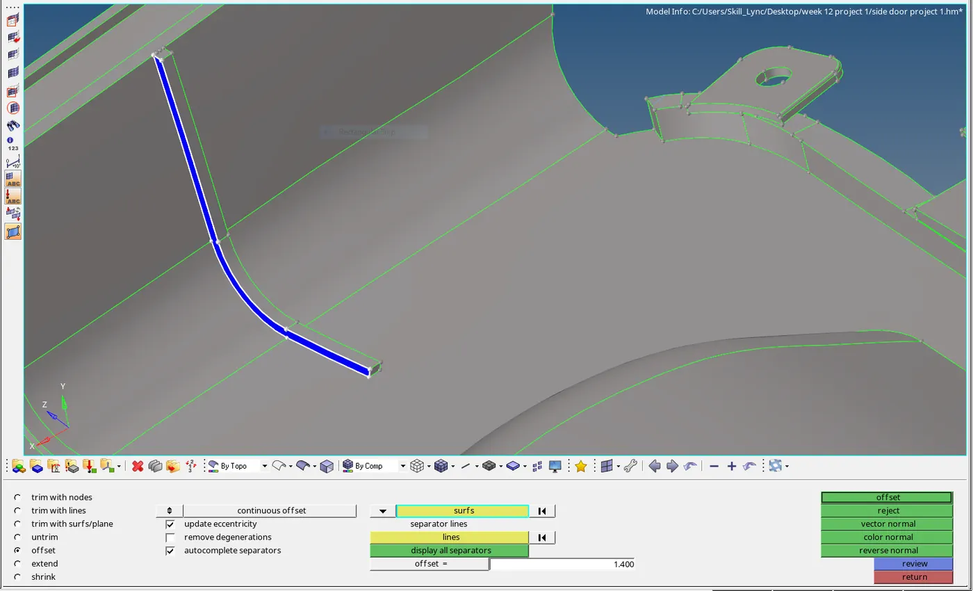
Fig. midsurface of rib by offset method
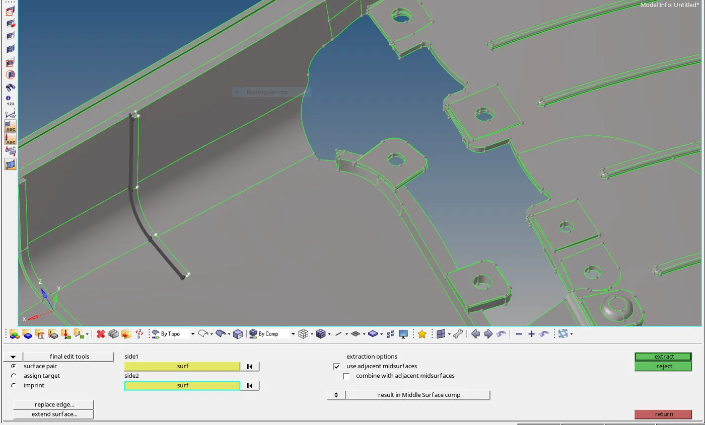
Fig. Midsurface of rib by final edit tool.
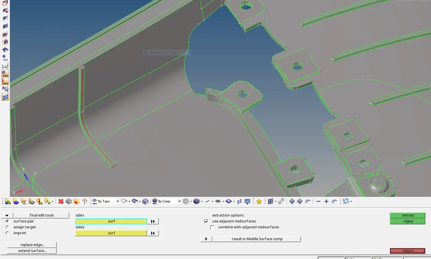
Fig. Midsurface generated of Rib by final edit tool method
now extend the rib to the base surface by using extend option which is in geo. > surface edit > extend > choose extend over edges > choose surf to extend is surf. to target . select the free edges line in line to extend over and select a surface over which line is extended in surf. to target then extend.
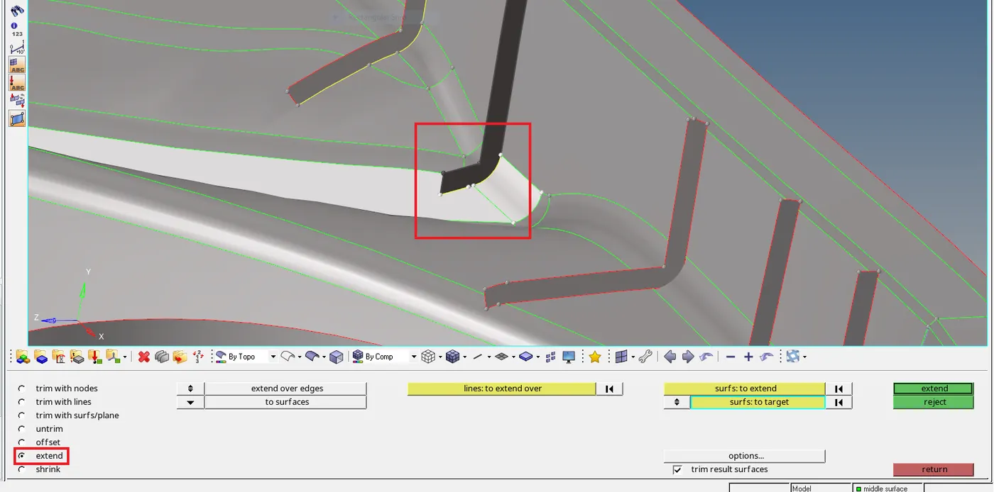
Fig. extend option (extend rib to parent or base surface )
4. Perform the 2D mesh on the midsurface - In order to mesh the midsurface first we input the given quality criteria and target element size as 4mm and element shape as mixed.

Fig. Given quality criteria
We mesh the complex surfaces first in order to maintain the proper mesh flow and make meshing easier while meshing the midsurface we make sure that we maintain the trias percentage as low as possible. while meshing curved or complex surface if the mesh doesnot properly catch the surface then we increase or decrease the node count so that mesh attaches the surface properly.
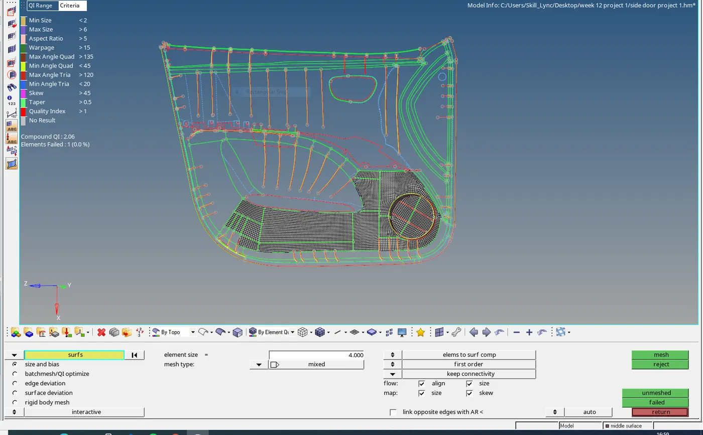
Fig. Meshing
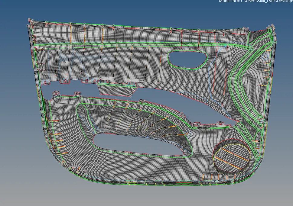
we use the smooth option while meshing in order to maintain the proper mesh flow. In order to mesh the rib some time there may be some node connectivity issues with the base mesh so we rectify this with mesh edit tool option . Go to 2D > Mesh edit >imprint > source select node in rib element > destination select base element > layer 3 > create. so now the nodes of rib getting connect with the base node.

Fig. Mesh edit tool
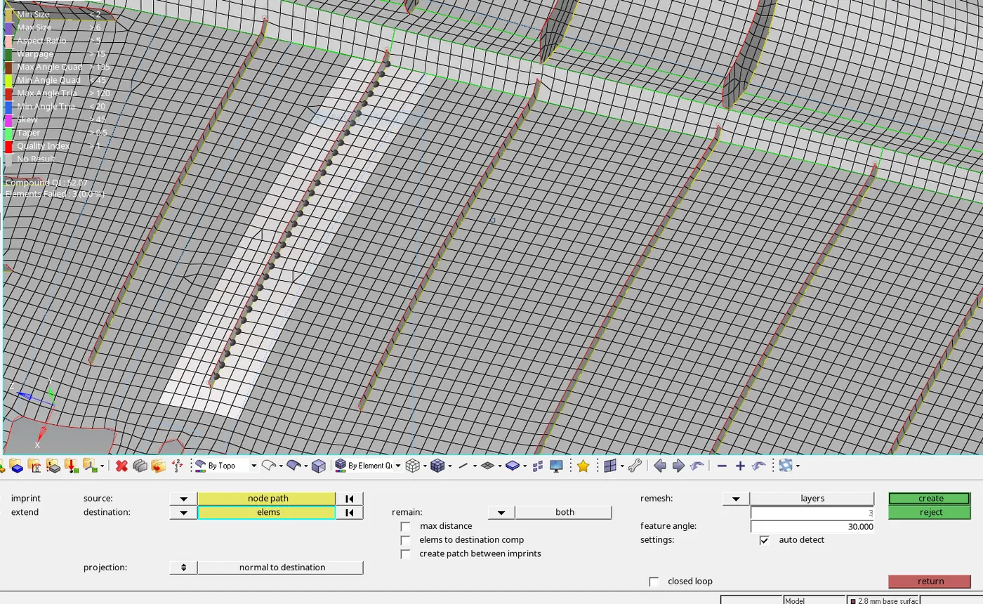
Fig. Mesh edit tool use for node connectivity of rib with base surface
5. Eliminate the failure element as per given quality criteria - After meshing the midsurface we check for element failure as per given quality criteria .this is performed in 2D > quality index > check element. we use various option like swap edge, drag element, split element etc in order to eliminate the errors caused due to violation of quality criteria
we eliminate the rotating quads and trias present near the free or feature edges. we also reduce the trias concentration by dragging the trias to the free ends or combing the opp. trias by dragging them near to each other. There may be lot of quality errors which fails for warpage ,min. length, max. length, aspect etc, so we rectify all the quality errors by using quality tools. Min. or max. length error can be rectify by increasing or decreasing the distance between two nodes. For warpage we used translate option by shift + F4 and select the node give direction and magnitude or icrease or decrease the angle by translate "+" "-" option. you can check the warpage element angle by press F10 and click on the element and in display its shows angle.
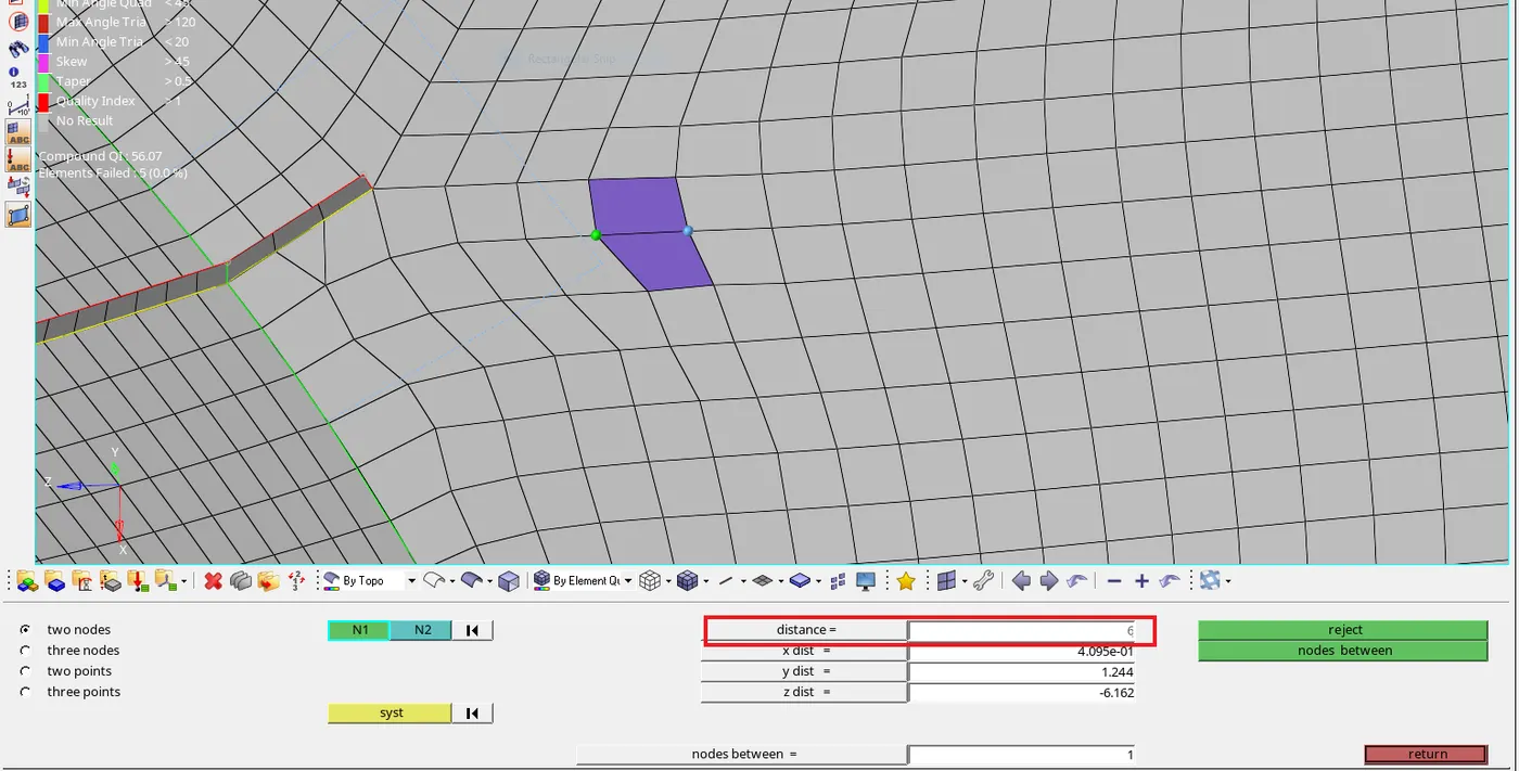
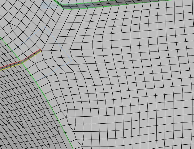
Fig. max length error Fig. Max. length error get fixed
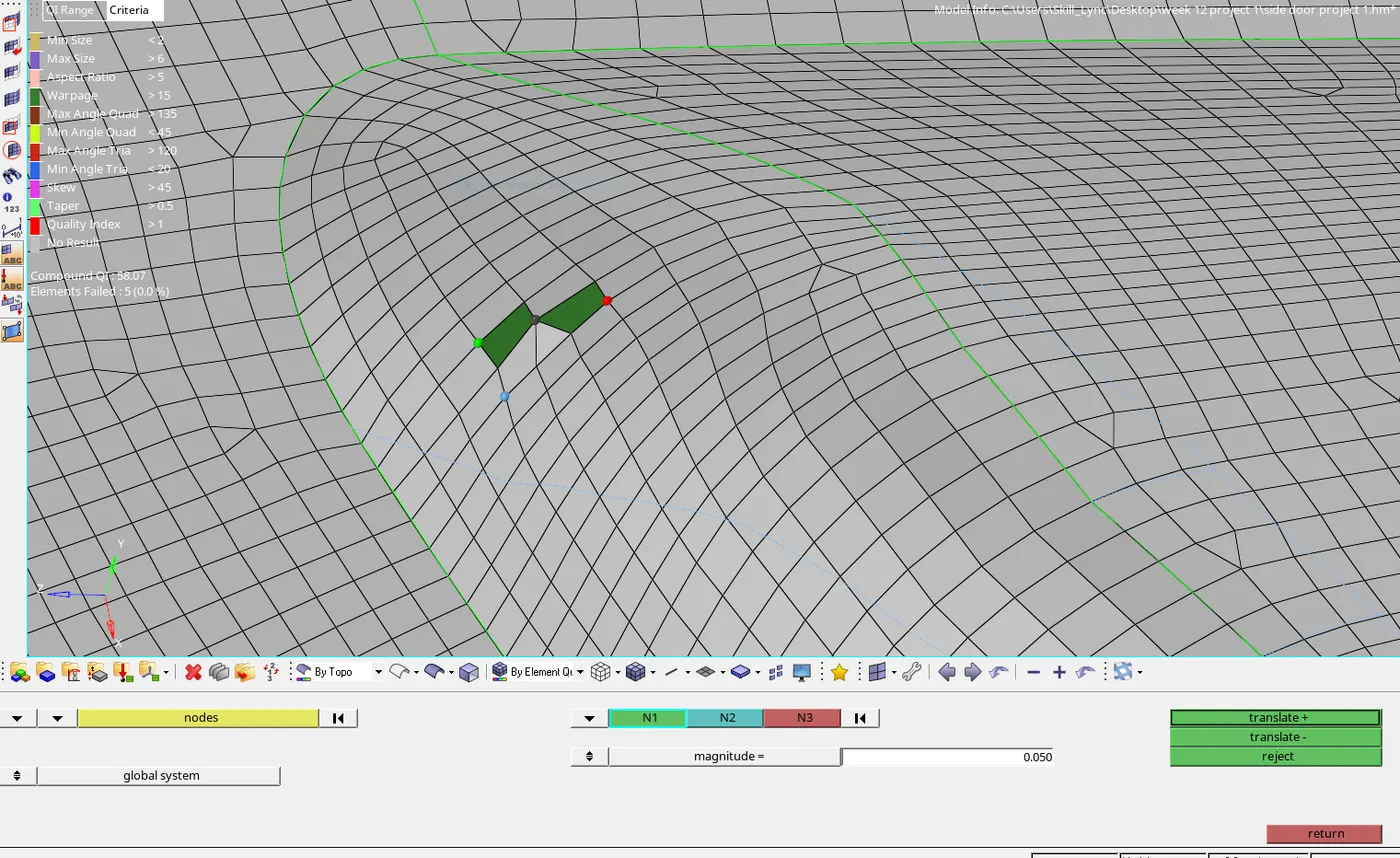
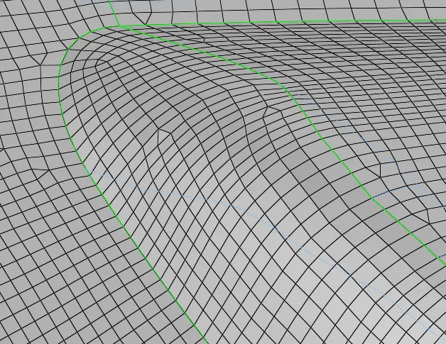
Fig. Warpage error Fig. warpage error fixed by translate option
there may be some other important parameter for tria management.
- No trias in corner or edges.
- No opposite trias.
- No back to back trias.
- No trias in fillet or hemming.
- No rotational quads.
6. Assign the thickness to model and convert shell element into solid elements - After completion of meshing, now we assign the thickness to midsurface. For assigning the thickness we create the property and in property we add the thickness value . now we create a component and in component we add a mesh of different thickness by using tool organize command. Go to tool > organize > collector > select the element > select desh component part which you make new component > move. Now for assigning thickness go to component and right click there is option of assign ,now click them . A separate panel is open now there is property column is there so we select the property id into them and apply them.
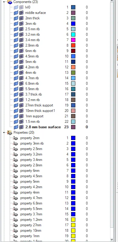
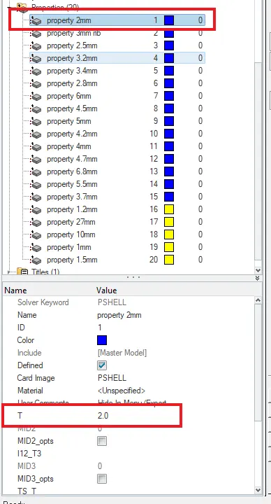
Fig. create component and property Fig. Give thickness to property id
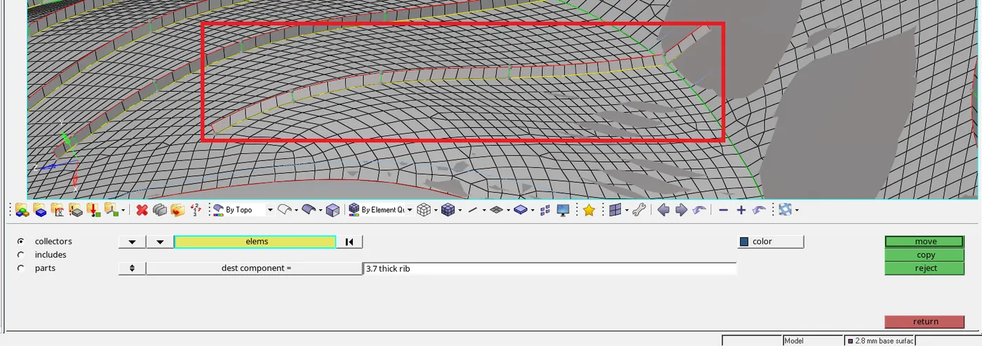
Fig. Move element to component with respective thickness
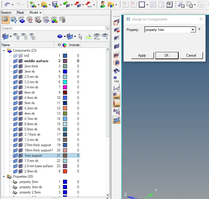
Fig. Assign property to component
To see the model in solid go to 2D detailed element representation tab.
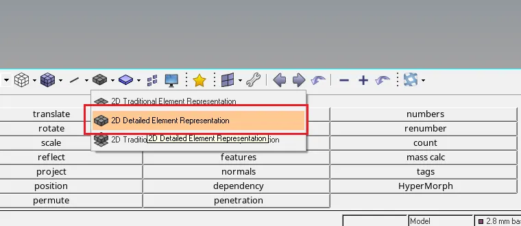
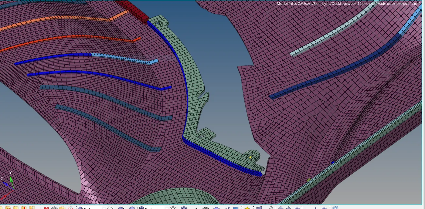
Fig. After assigning thickness
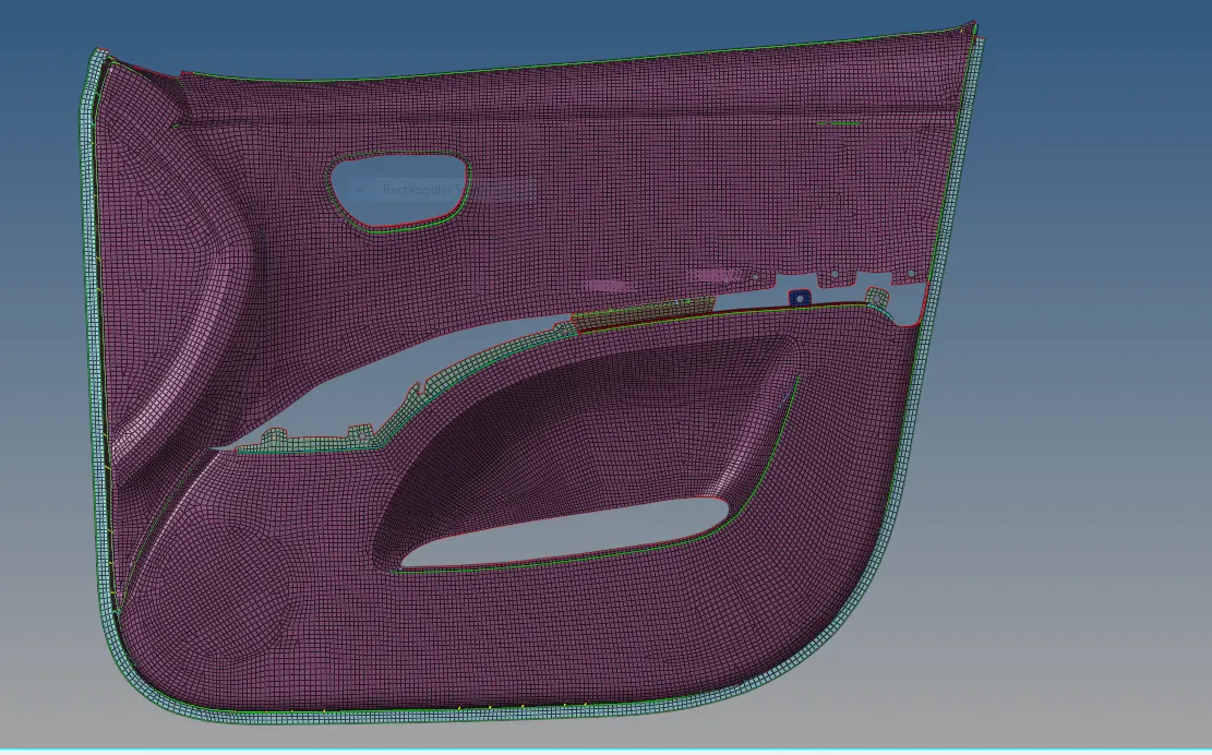
Fig. Final model
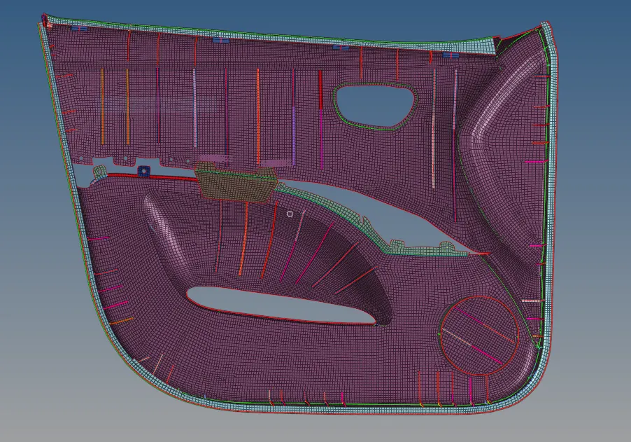
Fig. Final model
CONCLUSION - here conclusion is that for complex model auto midsurface gives us not accurate midsurface so its better to extract midsurface manually in complex model and also start meshing in complex shapes first then moves through them .