Week 12 - Project-1
project - 1
Objective - To mesh the given side door model and assigning thickness to the elements and following the quality criteria given as below -:
| sr. no. | quality criteria | value |
| 1. | Aspect ratio | 5 |
| 2. | skewness | 45 |
| 3. | warping | 15 |
| 4. | taper | 0.5 |
| 5. | minimum length | 2 |
| 6. | maximum length | 6 |
| 7. | min. angle quad | 45 |
| 8. | max. angle quad | 135 |
| 9. | min. angle tria | 20 |
| 10. | max. angle tria | 120 |
| 11. | tria % | 10 |
target element length - 4mm
Procedure -
- In the first step imported the cad model in the hypermesh window by clicking on the import button.
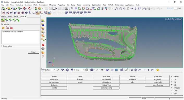
picture representing the imported cad model (.hm file) in the hypermesh window.
- As the model is a plastic component and not having a constant thickness so auto midsurface is not the good option to extract the midsurface. To make the model simple for the manual midsurface extraction trimmed the model in the z-axis approximately at center by using the trim with surface/plane option under the surface edit panel under the geometry page.
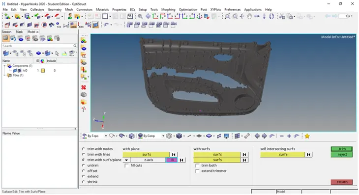
picture representing use of surface with plane option to trim the model in the z-axis.
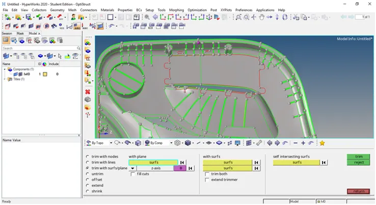
picture representing the cad model trimmed from base point in the z-axis.
- In the next step created another component in the tab area and organised the one trimmed part of the component in that component collector by using the organise option under the tool page.
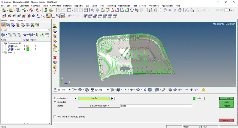
picture reprsenting the use of organise command to organise the one part of component in the other created component collector in the tree area.
- In the next step hided the one component and used the two point option under the distance option in the geometry page to check the thickness of the surfaces.
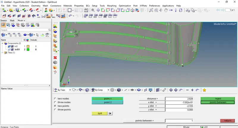
picture representing the use of two point distance option to measure the thickness of the surfaces.
- In the next step created another component collector named as midsurface in the tab area and used the offset command under the surface edit option to extract the manual midsurface.
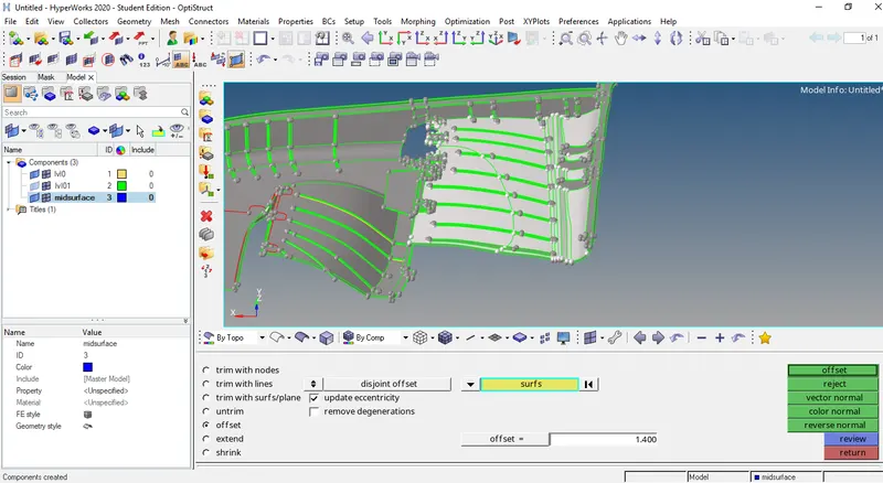
picture representing the use of offset command for extracting the midsurfaces.
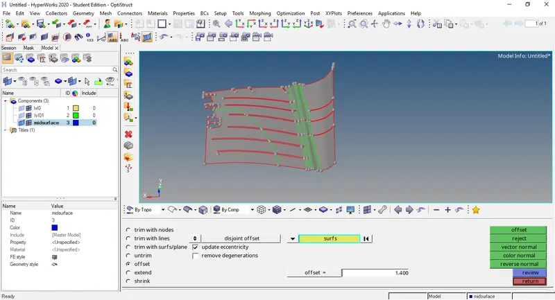
picture representing the midsurface extracted by using the offset command under surface edit panel.
- In the next step as we can see that there is gap or no surfaces at the places where the ribs are present.To fix this we can use the Ruled command as well as spline filler command. Both commands present under the surface edit panel option. But ruled is used to create only flat surfaces so to create the surfaces at the curvatures we use the spline/filler or filler surface option under the quick edit panel.
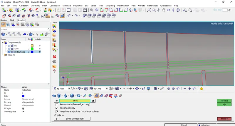
picture representing the use of spline/filler option to create surfaces at this curvature.
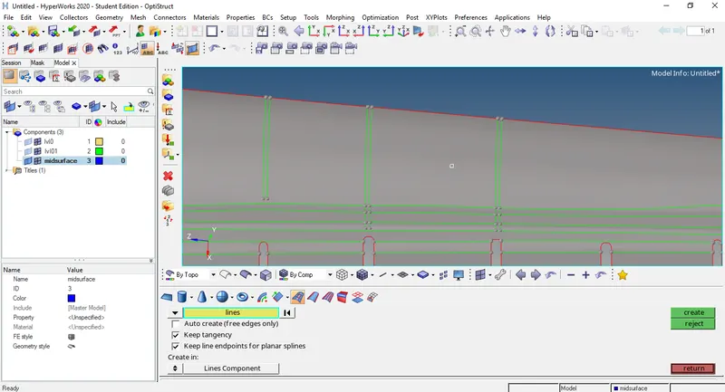
picture representing the surfaces created at the curvature by using the spline filler option.
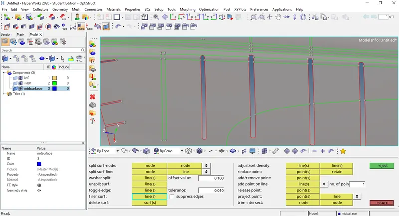
picture representing the use of filler surface option for creating the surface at that rib area which is enclosed.
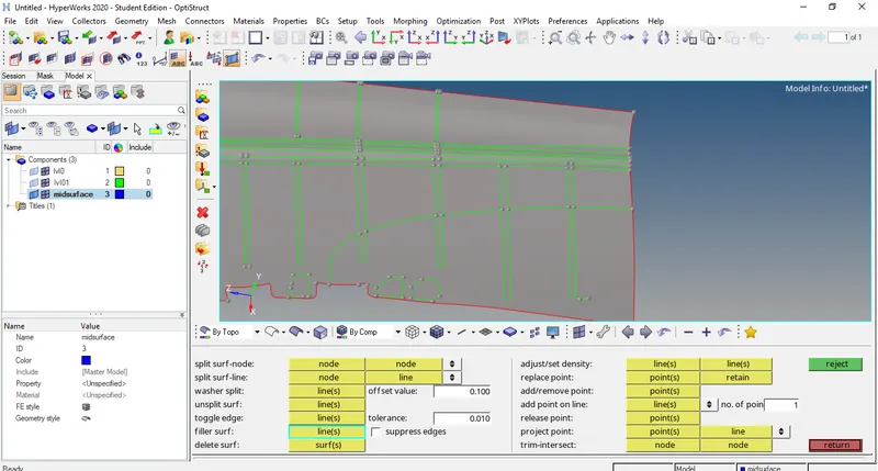
picture representing that all vacant surfaces are filled or created by using the filler surface option.
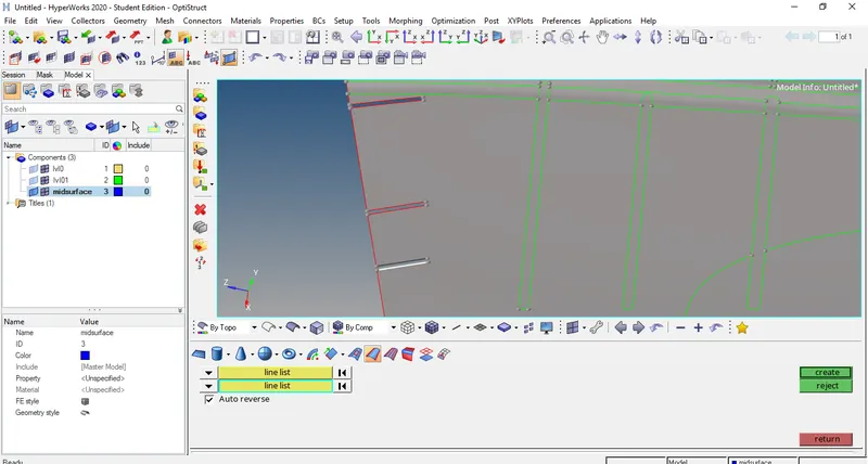
picture representing the use of ruled command to create surfaces at these vacant areas which is a flat surface.
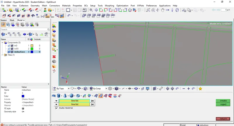
picture representing that all flat surfaces created at those vacant areas.
- In the next step extracted midssurfaces for adjacent surfaces by using the offset command and to connect or join these surfaces used the surface extend command under the surface edit panel. In this selected the extend over edges dropdown and surfaces to target because here we have to connect the surface with the adjacent surface and there is no need for giving any distance value.
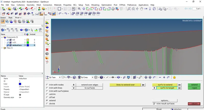
picture representing the midsurfaces extracted for the adjacent surfaces by using the offset comamand and red line indicates that there is no connection between the surfaces.
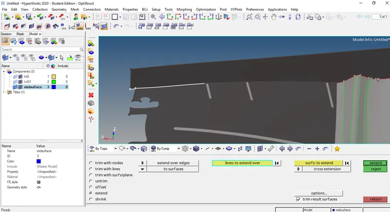
picture representing the use of extend command under surface edit panel to connect the adjacent surfaces.
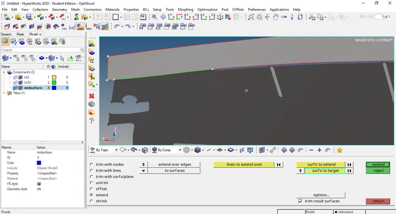
picture representing that the surfaces are connected by using the extend command.
- By using the distance, offset, extend, spline/filler, ruled and toggle command are the prominent used command for extracting the midsurface of the base surfaces of the component i.e excepting the ribs.
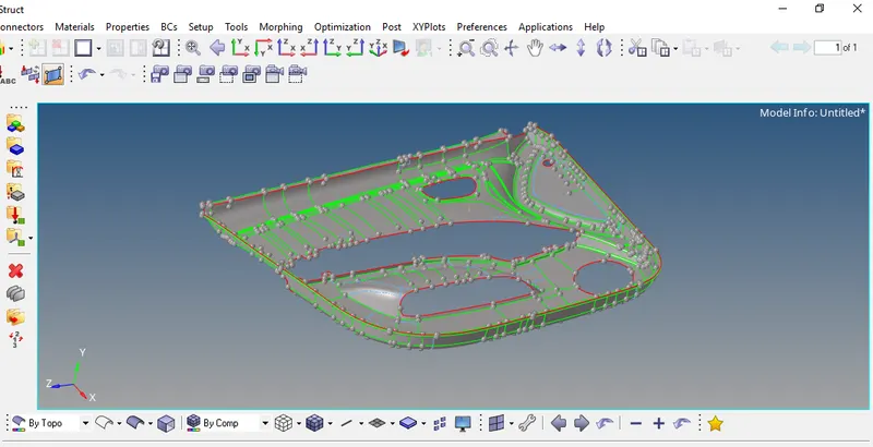
picture representing the midsurface extracted for the base surfaces mainly by using the distance, offset, extend, spline/filler, ruled and toggle command.
- In the next step extracted the midsurfaces of the ribs by using the surface pair under final edit tools under the automidsurface option.As the thickness of the ribs is not constant may be becuse of the given model is scanned model not an actual cad model so this surface pair tool is very handy at this situation.
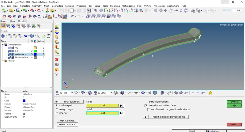
picture representing the use of final edit tools surface pair option under auto midsurface option to extract the midsurfaces of the ribs.
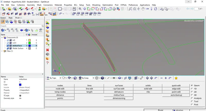
picture representing the midsurface extraction of the rib by using the final edit tools under automidsurface option.
- As we can see that there is red line between the midsurface of the rib and the base surface means these surfaces are not connected so to connect these surfaces used the extend command under the surface edit panel and selected the extend over edges to surfaces and surfaces to target in the dropdown button.
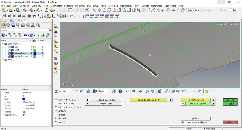
picture representing the use of extend command to connect the rib midsurface with the base midsurface.
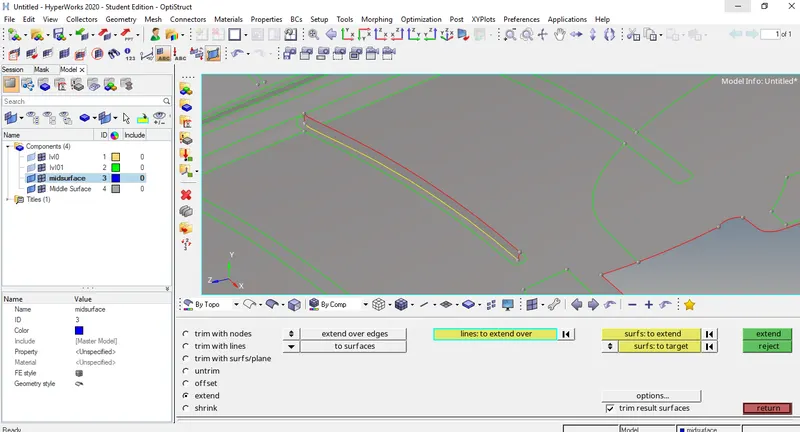
picture representing the midsurface of the rib and base midsurface are connected by using the extend command (yellow line indicate that the rib midsurface is connected with base midsurface)
- Also there iare two more method to extract the midsurface of the ribs. midline option under the line command and the offset command under surface edit panel. As we have discussed about the offset command while extracting the base midsurface discussed above. So here we get the exposure of midline command. As midline creates the line exactly in between the lines that we select so it is also very useful tool to extract the midsurfaces where thickness is not constant.
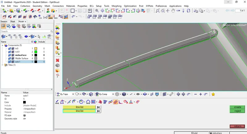
picture representing the use of midline command for creating line exactly in between the selected lines.
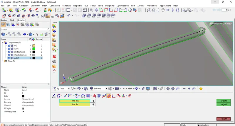
picture representing the midline created between the selected lines using the midline option.
- In the next as this midline is above the base surface to project this midline on the base midsurface used trim with line option under the surface edit panel and selected the free lines and normal to surface in the dropdown buttons.
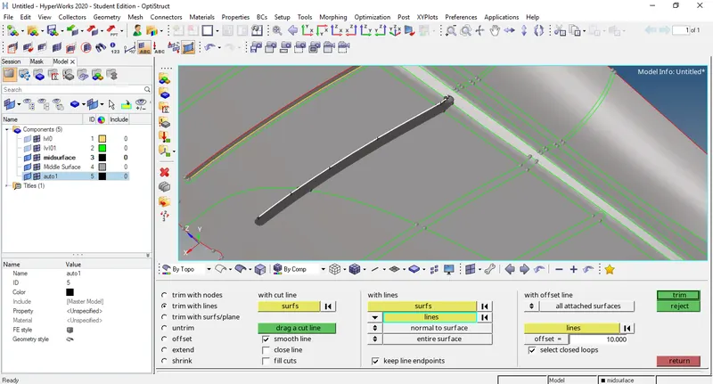
picture representing the use of trim with lines option under surface edit panel to project the midline on the base midsurface.
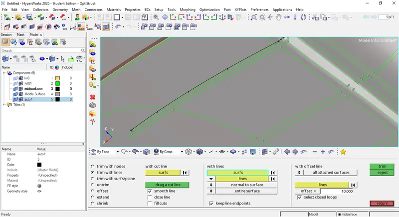
picture representing the base midsurface trimmed with the reference of midline by using the trim with line option.
- In the next step to create the surface between the trimmed line and the midline used the ruled command.
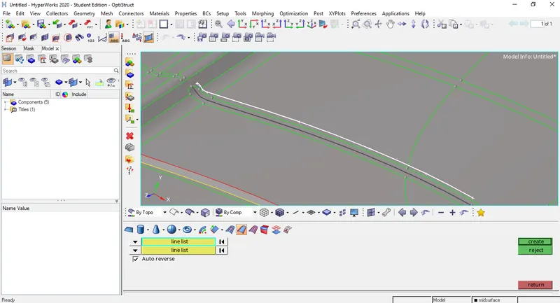
picture representing the use of ruled command for creating surface between the midline and trimmed line on the base midsurface.
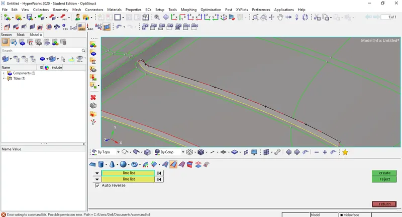
picture representing the midsurface created between the midline and trimmed line i.e midsurface of the rib is extracted.
- In this way each rib midsurface is extracted and each feature is added in the midsurface with respect to the parent geometry.
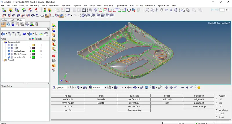
picture representing all features added in the midsurface with respect to the parent geometry.
- In the next step to create circle on the midsurface same as like the parent geometry.firstly i creted the node at the center of the circle by using the arc center option under the node option available.
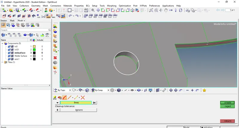
picture representing the use of arc node option to create the node at the center of the hole.
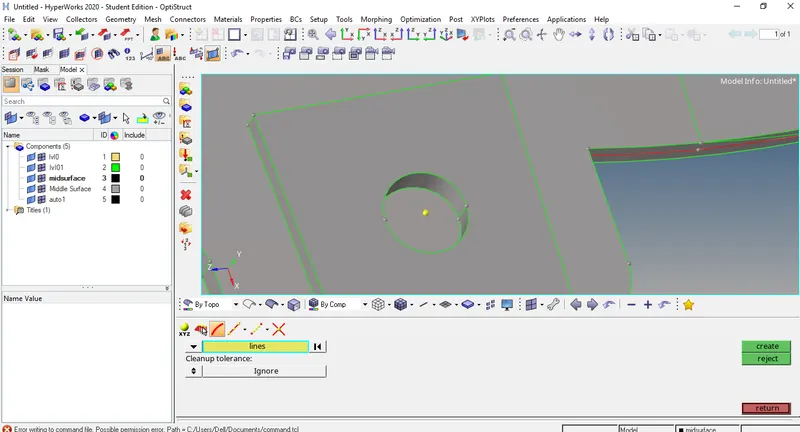
picture representing the node is created at the center of the circle by using arc node option.
- In the next step as this node is above the midsurface and projected this node on the midsurface using the project option under the tools page.
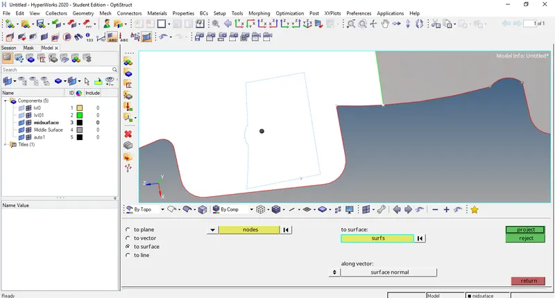
picture representing the use of project option to project the node on the midsurface which was laying above the midsurface.
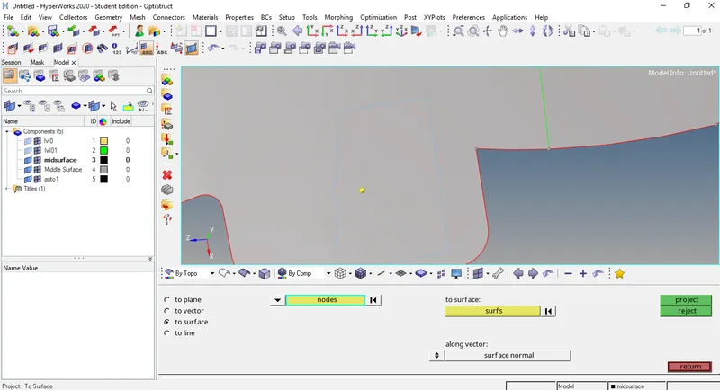
picture representing that the node is projected on the surface by using the project option.
picture representing the use of circle option present under the line tool to create the circle.
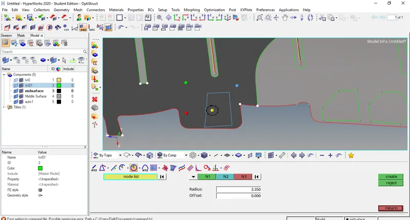
picture representing that the circle is created having radius of 3.35mm by using the circle option.
- In the next step trimmed this created circle from the adjacent surface using the trim with line option under the surface edit panel.
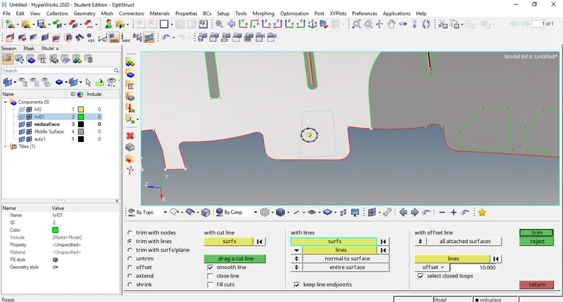
picture representing the use of trim with line option to trim the circle area from the respective adjacent surface.
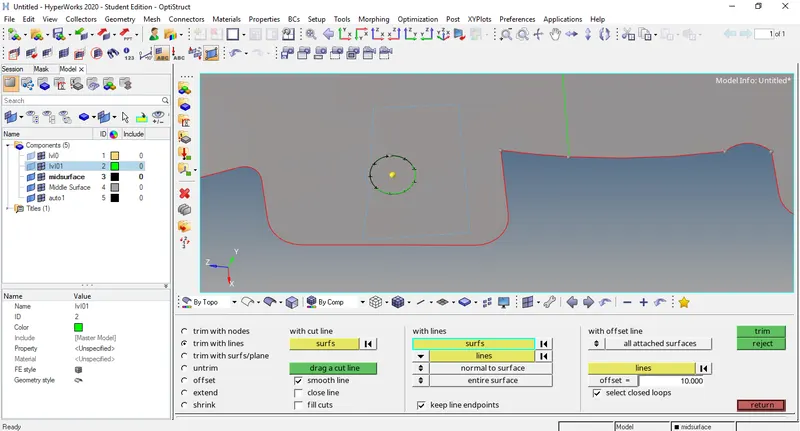
picture representing that the circle is trimmed using the trim with line option.
- In the next step deleted this circle by using the delete option by pressing f2 from the keyboard.
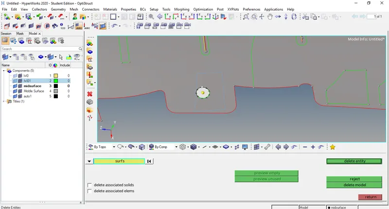
picture representing the use of delete option for creating circle same as the parent geometry.
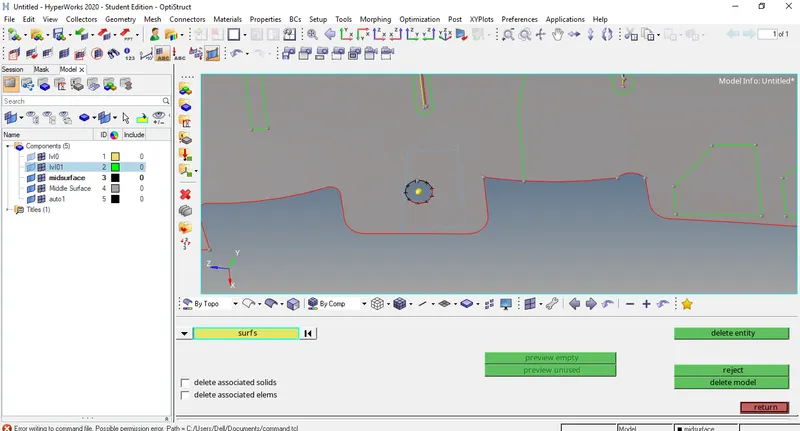
picture representing that the circle has been created in the midsurface by using the delete option.
- In the next step it is important to divide the surfaces wisely so that we can get a proper mesh and proper mesh flow. usually we divide the surfaces in small rectangular or square boxes so we can get good mesh.For doing this we use the split surface node option under the quick edit panel.
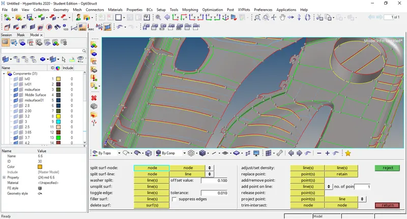
picture representing the bifurcation of surfaces into small boxes for getting the proper mesh and proper mesh flow by using split surface node under quick edit panel.
- I the next step by pressing F12 from the keyboard we get the 2d automesh panel where we select the mixed element of size 4mm. The reason for selecting the mixed element is that because the model is prepared for crash, impact and drop test where flow of energy is the main concern.If we select the quads instead of mixed elements then there will be rotation quads which divert and distract the flow of energy in the model and are not ideal for the crash and drop test. Having trias in these tests is fine to maintain the proper mesh flow that is why we used the mixed element instead of only quads elements for the 2d meshing or shell mesh.
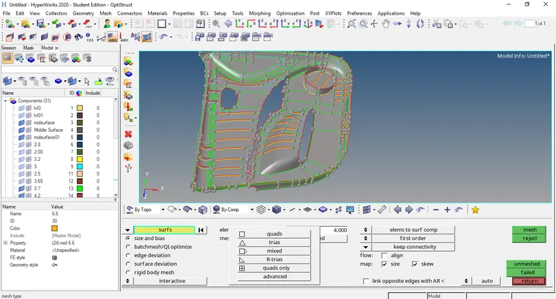
picture representing the element type mixed elements for 2d meshing having target length of 4mm.
- In the next step done meshing on the surfaces and also toggled some feature lines using the toggled command and these feature lines are not important and having them we can get the improper mesh.
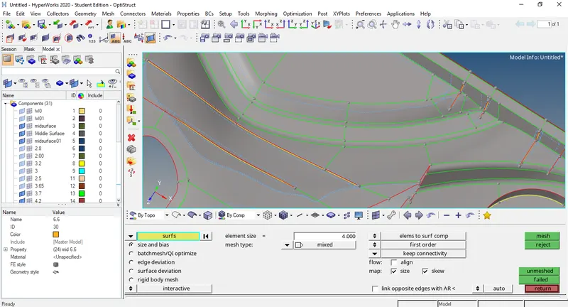
picture representing the toggle or defeature some feature lines which were present in the parent geometry but not good for the meshing i.e to avoid the element failure.
- In the next step done the 2d meshing on whole component by using surface surface approach and remeshed many areas multiple times to get the proper mesh at those areas. There are certain rules for getting proper mesh flow which are listed below -:
- No tria elements should be opposite to each other.
- No tria elements should be connected back to back.
- No tria elements should be on the edge of the geometry.
- No tria elements should be near the hole.
- No tria element should be on the feature and the fillet.
- Less tria concentration.
Considering these factors or rules meshed the whole component by using the automesh command.
- Also, as feature line is important and it implies about the plane change so keeping the elements projected on the feature line is important specially at the areas where surface is changing from flat surface to fillet or tapered shape etc. and it is done by using the project option.
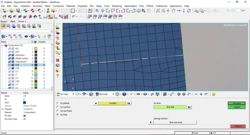
picture represent the use of project option for projecting elements on the feature line.
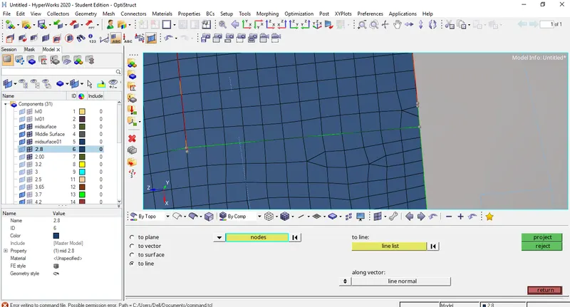
picture representing the elements are projected on the feature line using the project option.
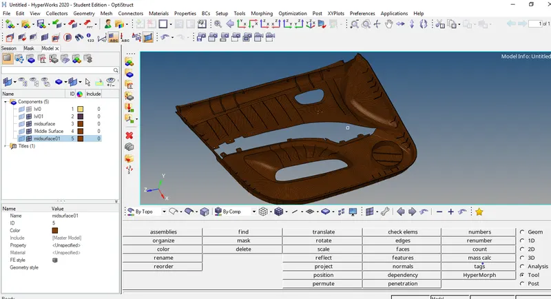
picture represent the meshing is done on the whole model.
- In the next step used the find edges option to ensure that all the elements are connected with each other or there is no free edge in between.
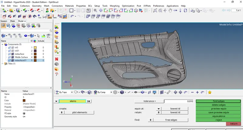
picture represent the use of find edge option to ensure the connectivity between the elements.
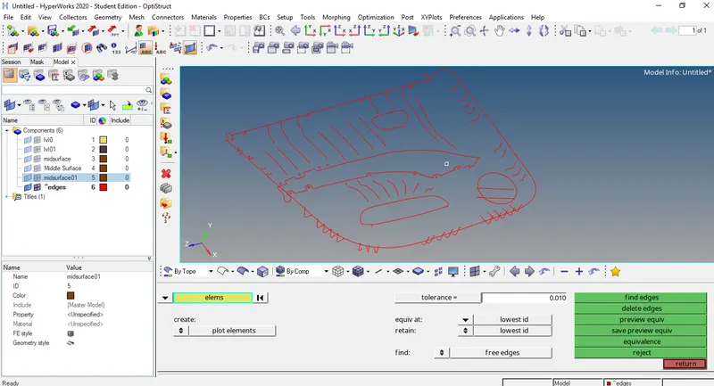
picture represent the free edges in the model which are not in between rather at the edges.
- In the last step, assigned thickness to the elements with respect to the parent geometry and like ribs having not the constant thickness througout so average thickness is considered. For this created multiple component collector and multiple properties of different different thicknesses in the tab area and organised the respective elements to the respective collector using the organise tool option.
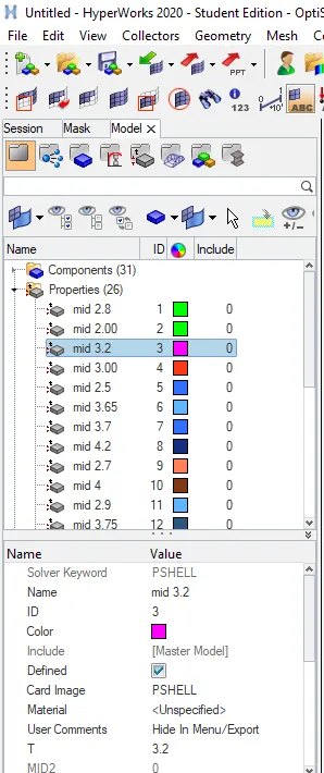
picture representing in the tab area multiple properties created with respect to required thicknesses.
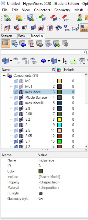
picture representing the different components collector created named with the thickness values and respective properties assigned to respective component collector.
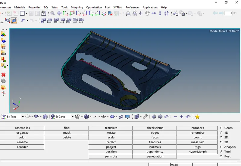
final picture of the model and represent that the respective elements are organised in the required element collector.
Result -
- Manual midsurface extracted.
- midsurface of the ribs extracted using the final edit tools automidsurface and midline option.
- Bifurcated the geometry into small areas to get the control of the mesh as well as proper mesh.
- Defeature the areas where elements gets failed.
- Done automesh with target element size of 4mm.
- Used the Check elements option by pressing f10 from the keyboard and checked the quality criteria of the elements.
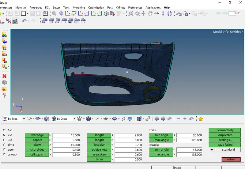
picture representing the check elements option required for the quality criteria.
- Fixed the failed elements by doing remesh or by using the node distance option.
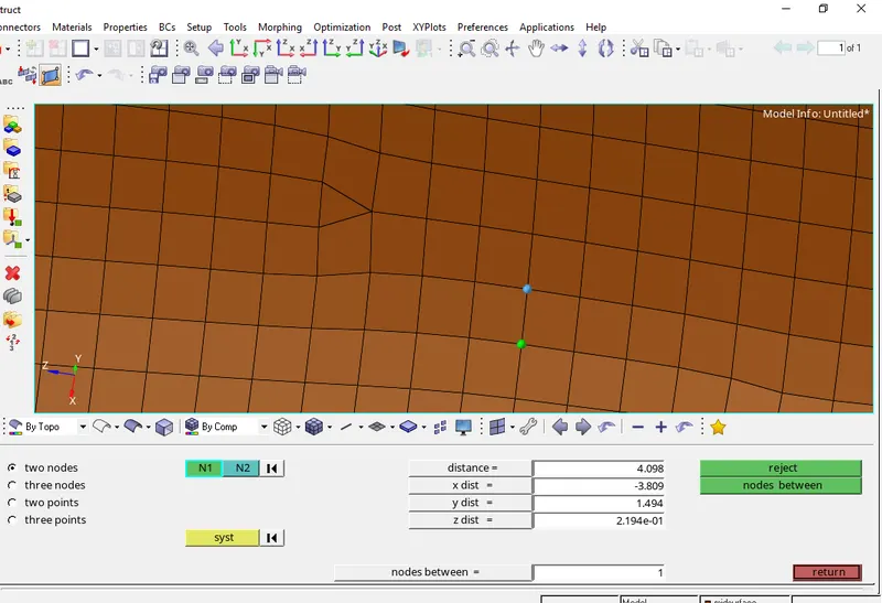
picture representing the use of node distance option to fix the elments failed for minimum and maximum length.
- To connect the elements at certain areas used the replace node option by pressing f3 from the keyboard.
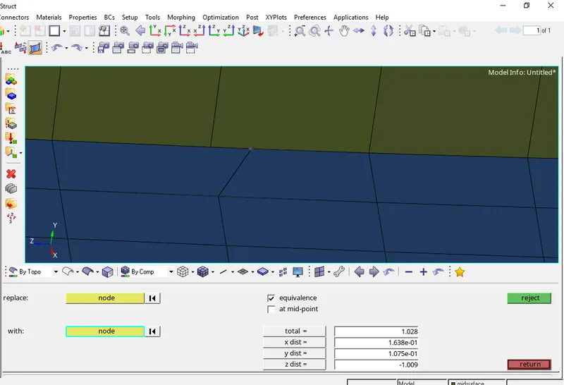
picture representing the replace node option is used to connect the elements.
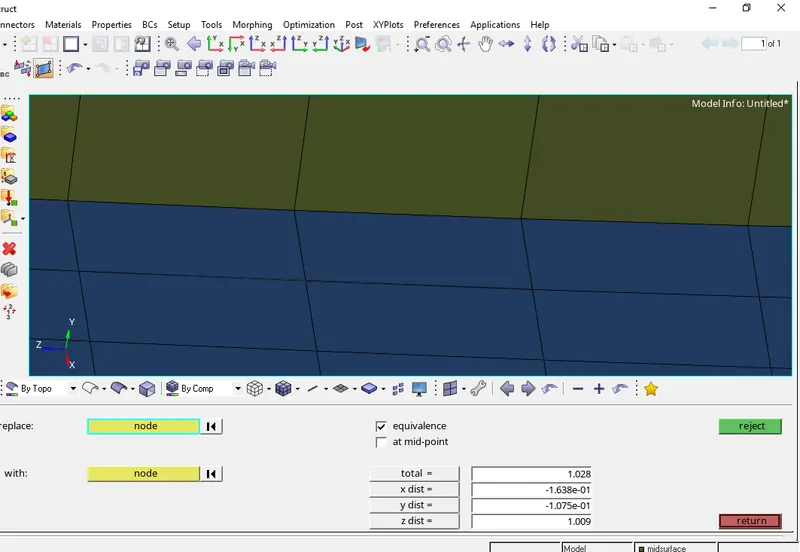
picture representing the elements are connected by using the replace node option.
- No free edges in the model.
picture representing the no free edges in the model i.e each and every element is connected.
- Almost 100% elements passed the quality criteria and very few elements i.e 0.0% elements failed at vulnerable places where fixing is not possible.
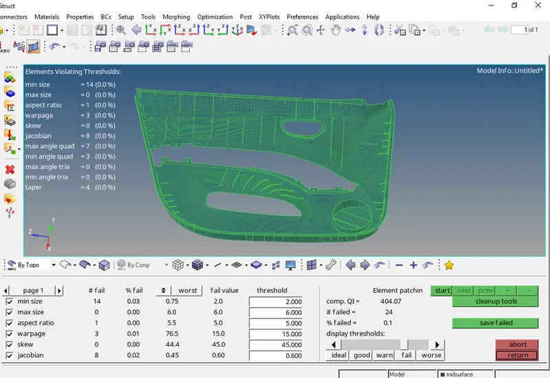
picture representing almost every element passed the quality criteria.
- Created multiple components collector and multiple properties of the required thicknesses and assigned properties to the respective components and organised the elements in the required component collector.
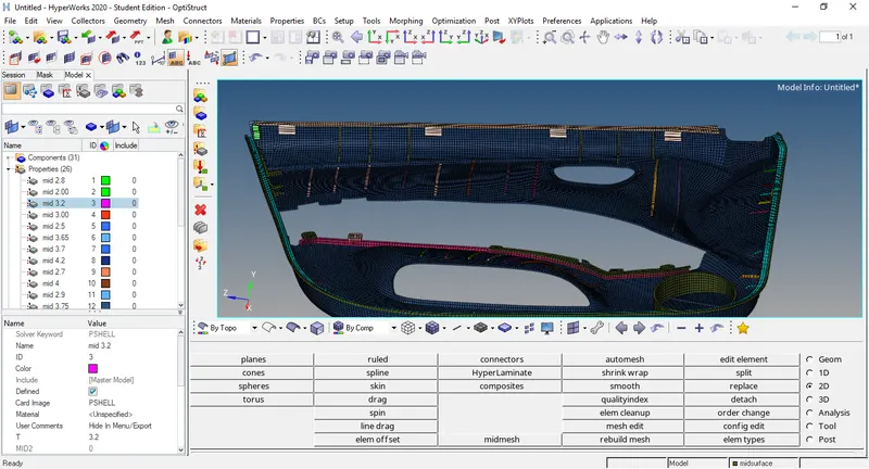
picture representing the enabled 2d detailed element representation created components collector as well as properties in the tab area and assigned thicknesses to the elements and organised the elements in the required component collector.