Project 2
PROJECT - 2
Objective - To mesh the given Floor Panel with target element length = 5mm and assigining thickness to the component.
The quality criteria for meshing this cad model is given as below :-
| Sr. no. | Quallity criteria | Value |
| 1. | Aspect Ratio | 5 |
| 2. | Skewness | 45 |
| 3. | Warping | 15 |
| 4. | Taper | 0.5 |
| 5. | Min. length | 2 |
| 6. | Max. length | 8 |
| 7. | Min. angle Quad | 45 |
| 8. | Max. angle Quad | 135 |
| 9. | Min. angle Tria | 20 |
| 10. | Max. angle Tria | 120 |
| 10. | Tria % | 10 |
Procedure - The procedure for accomplish meshing on this given floor component is given as below :-
- In the first step imported the Cad model in the hypermesh window by clicking on the import button.
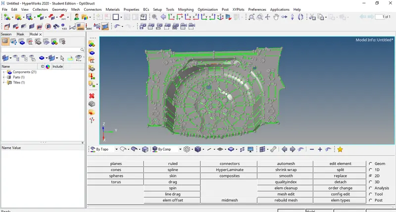
Picture representing the imported cad model (floor panel) in the hypermesh window.
- In the next step put the model in the wireframe mode to ensure the connectivity between the surfaces i.e (green lines).
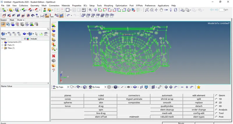
picture representing the given cad model is put under the wireframe mode to ensure the proper connectivity between the surfaces i.e no red lines and yellow lines in the model.
- In the next step geometry cleanup done on the model. First zoom in the areas where the red lines and yellow lines found in the model then put the model into shaded view and used the mask surface options at that particular areas to know more about the surface issues.
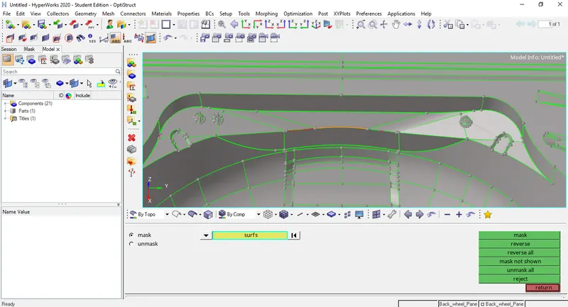
picture representing area where isssues in the surface is found and turned the model in shaded mode.
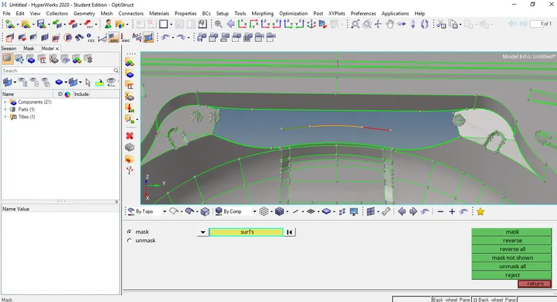
picture representing the use of mask surface option to know about the issues in the surface.
- In the next step used the delete surface option to delete these extra surfaces.
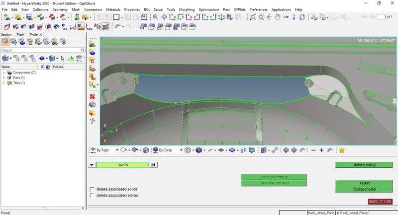
picture representing the use of delete surface surface option to delete the extra surfaces.
- In the next step unmasked all the surfaces and used the replace point option and toggle edge option to fix the free edges in the surfaces.
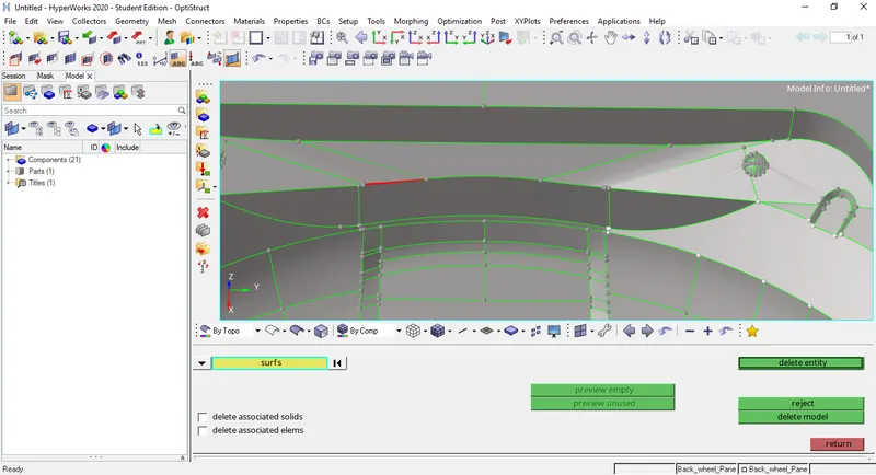
picture representing all the surfaces unmasked by using the mask surface option.
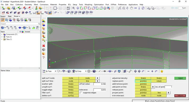
picture representing the use of replace point option and toggled edge option to fix the free edges i.e red lines.
- In the next step found some surface issues at the beads.
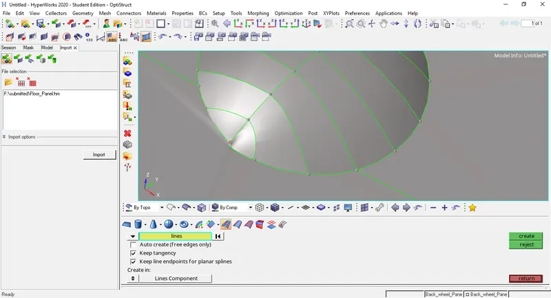
picture representing surface issues i.e open edges found at the beads.
- In the next step used the untoggled edge option to check the surface connectivity with the adjacent surfaces.
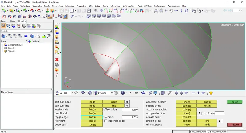
picture representing the use of untoggle edge option to check the connectivity between the adjacent surfaces.
- In the next step deleted the surfaces which were creating surface issues at that area.
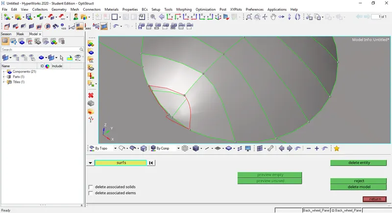
picture representing the surfaces deleted by using the delete option.
- In the next step used the ruled command under the surface panel option to create the surface at the base.
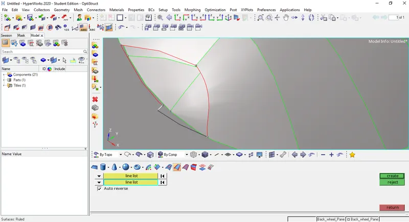
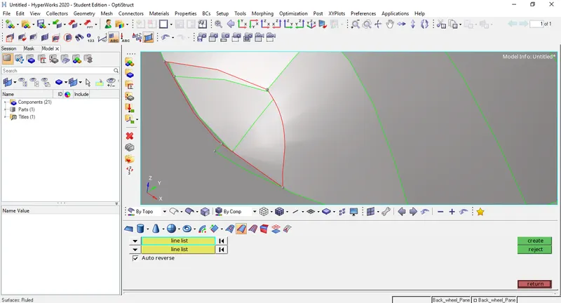
pictures representing the use of ruled command under surface panel to create the the surface at the base surface.
- In the next step to create the surface at the beads used the spline/filler option present under the surface panel. This results in creation of surface of desired output i.e same as required in the parent geometry.
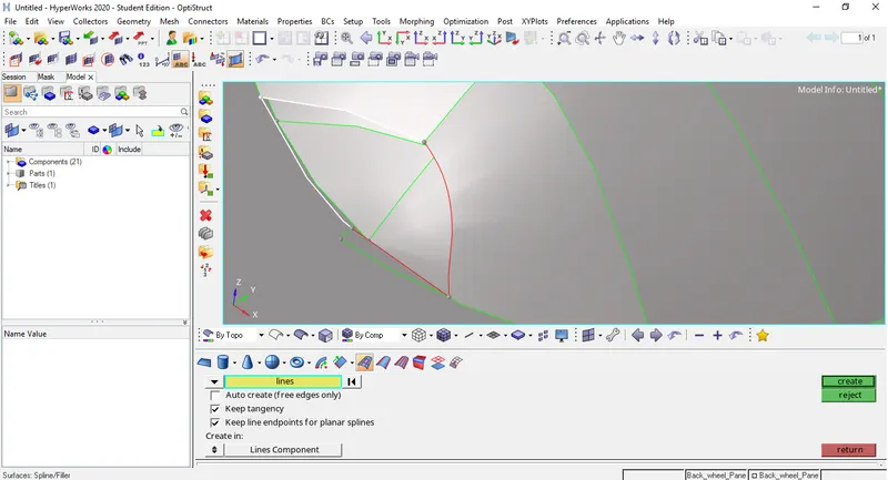
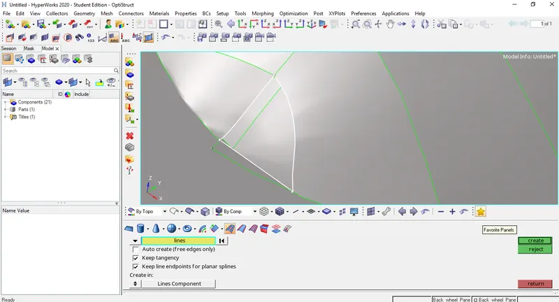
pictures representing the use of spline/filler option in the surface panel to create the surfaces at the beads.
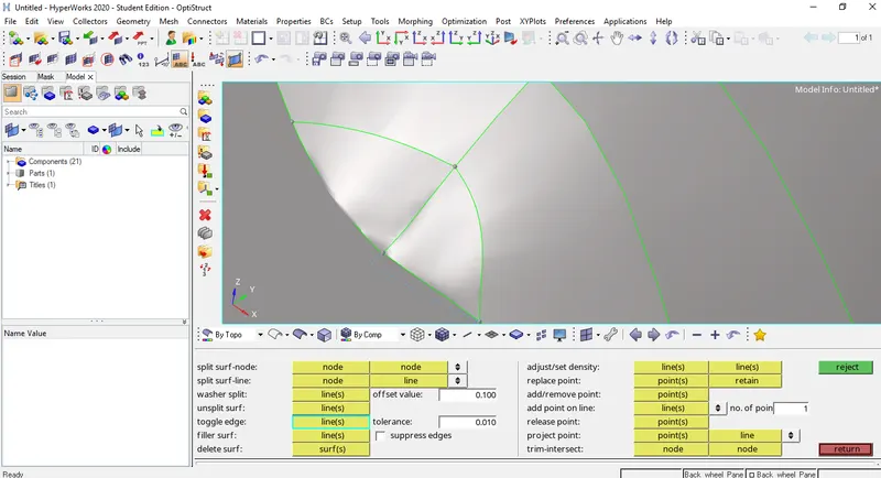
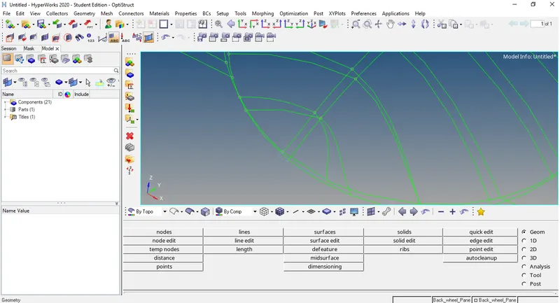
pictures representing the surface connectivity issues at that area is fixed by using the ruled , spline/filler and delete surface option and can be seen in the shaded and the wireframe mode.
- In the next step shifted to areas where surfaces connectivity was disturbed.
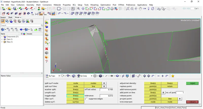
picture representing the area where surface connectivity is disturbed.
- In the next step used the untoggled edge, delete surface, mask and ruled surface to get proper connectivity between the surfaces.
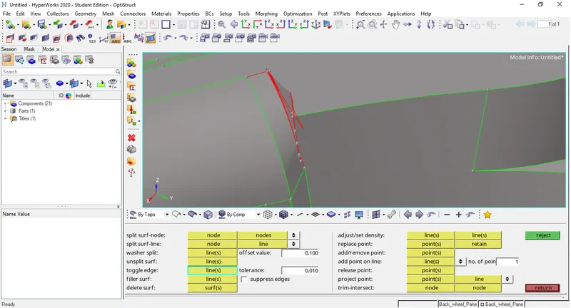
picture representing the use of untoogled edge to check the connectivity between the adjacent surfaces.
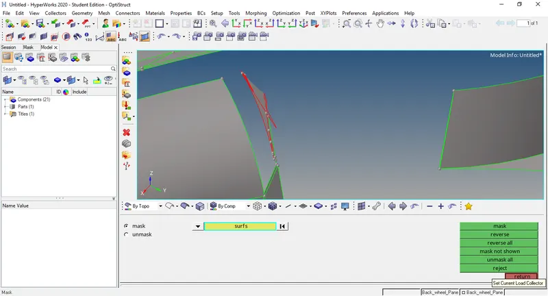
picture representing the use of mask surface option.
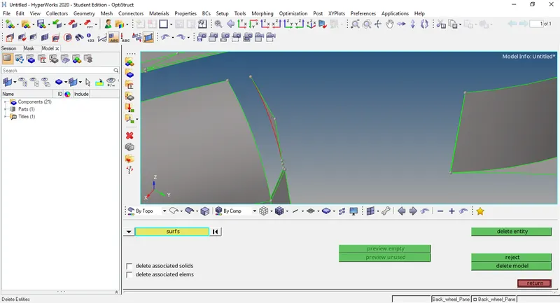
picture representing the use of delete surface option to delete the extra surfaces.
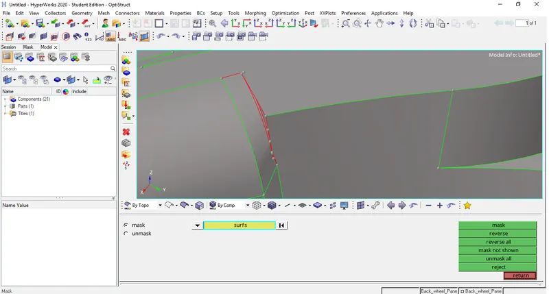
picture representing all the adjacent surfaces get unmasked by using the mask surface option.
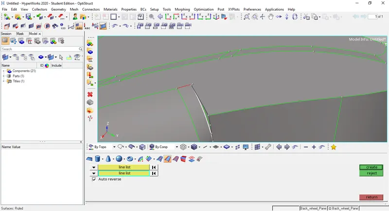
picture representing the use of ruled option to create the surfaces between the free edges.
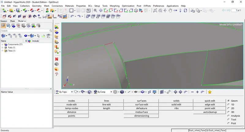
picture representing the surface created by using the ruled command.
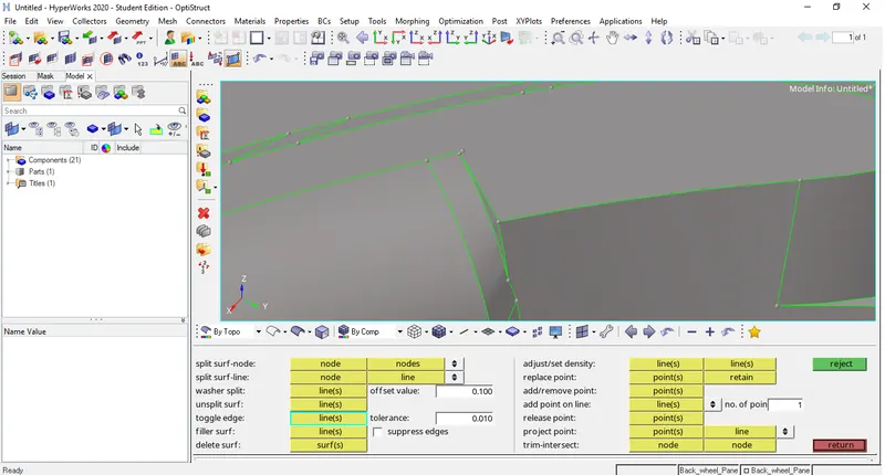
picture representing the proper connectivity between the surfaces is achieved by using all the tools as mentoined above.
- In the next step, found geometrical issues in the other region.some duplicate surfaces found. To fix this used the toggle, delete, filler and replace point option.
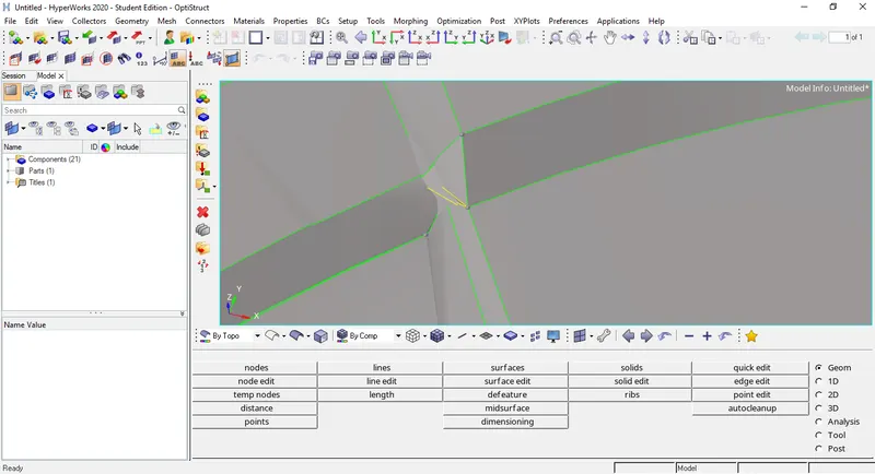
picture representing the geometrical issues found in the surface at that region.
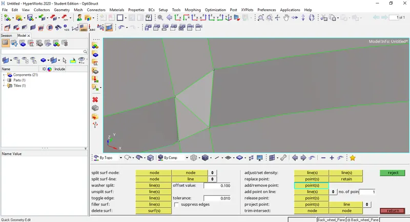
picture representing the geometrical issue fixed by using the toogle, delete, replace point and filler option.
- In the next step, after fixing all the geometrical issues in the parent geometry used the automidsurface option to extract the midsurface of the component. As the given component is the sheet metal metal component having uniform thickness of 0.75mm throughout the model. so autommid is the good option here to extract the midsurface. By using the offset automid get the more accurate results.
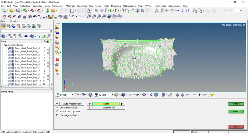
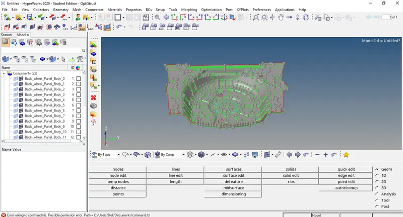
pictures representing the midsurface of the component is extracted by using the automidsurface option.
- In the next step after fixing some geometrical issues from the midsurface meshed the component and before that split the surfaces by using the split surface node option under quick edit panel so that better meshing results can be attained.
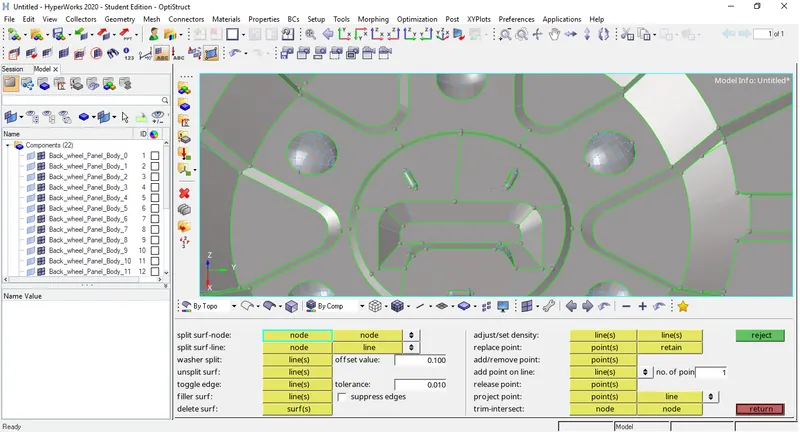
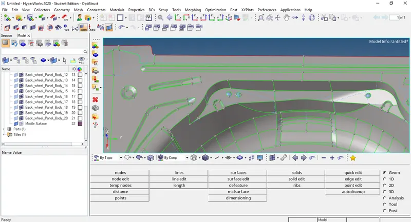
pictures representing the use of toogle and split surface node option to create the surface ideal for meshing.
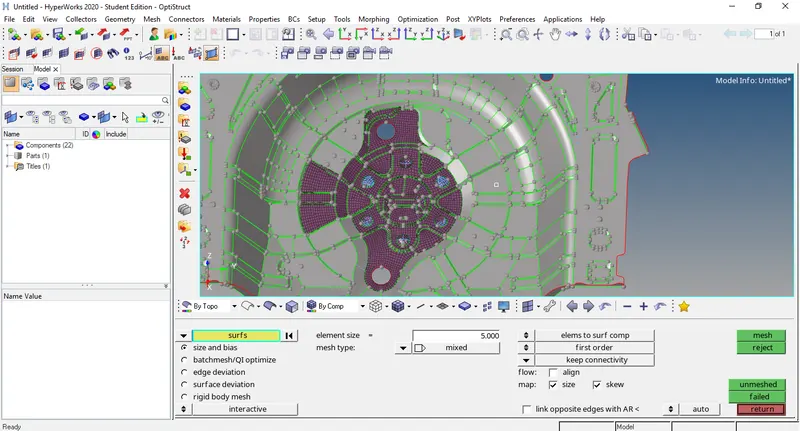
picture representing the surfaces meshed one by one by using the automesh option or by pressing F12 from thee keyboard having element size of 5mm and element type is mixed.
- In this way the whole model is meshed by approaching one by one surface for meshing.
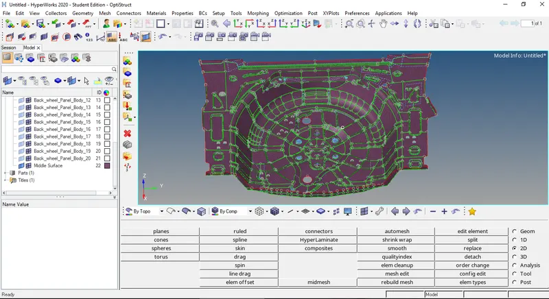
picture representing the whole model is meshed by using the automesh option.
- Few things or rules i followed while meshing this component.
- Remeshed the mesh multiple times to get the better mesh flow and mesh results.
- No opposite trias found on the same surface.
- No two trias touching each other.
- No trias touch the feature line.
These are the few general rules which we have to follow while meshing.
- But, at the sharp edges or curved areas where we cant do anything we have to make compromise with such rules of meshing. As in this model many sharp areas which are converging in nature and many curvature areas so meshed those areas accordingly.
- In the next step, used the quality check elements option to diagnose the failed elements which breaches the quality criteria parameters.
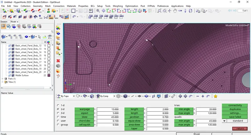
Picture representing the check elements option to diagnose the elements which breaches the quality parameters.
- In the next step fixed these failed elements by using the transalte option under the tools panel for the elements failed for minimum and maximum angle and warpage.
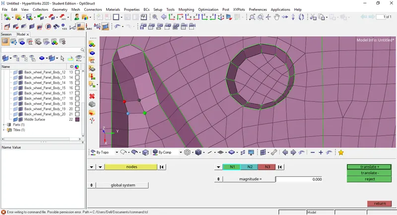
picture representing the use of translate option to fix the elements failed for minimum and maximum angle and warpage.
- In the next step used the distance node option to fix the mimimum and maximum length failed elements.
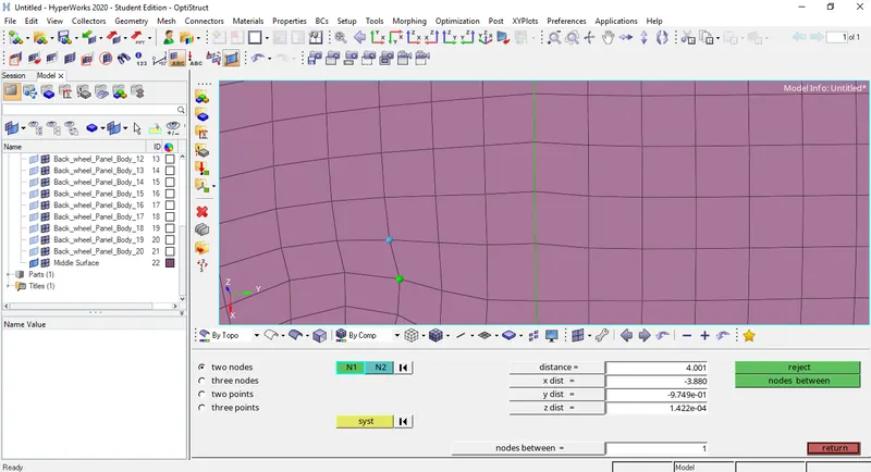
picture representing the use of distance node option to fix the elements fialed for minimum and maximum length.
- In the next step, as many tria elements were failing for skewness and minimum length at the sharp corners. To fix them make toggled the sharp edges and make cut before using split surface node option to fix these skewness and minimum length issue.
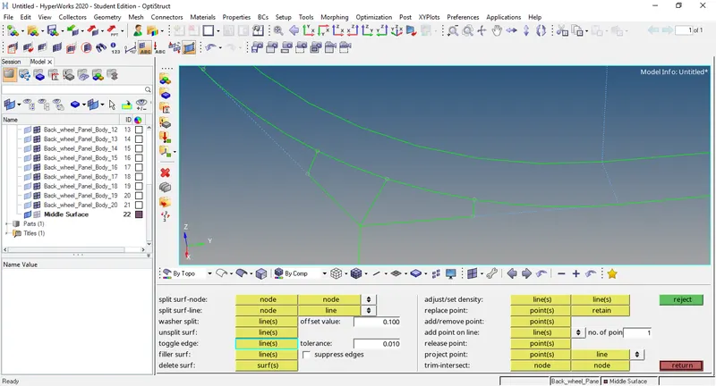
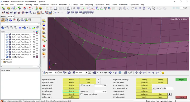
picture representing sharp edges toggled to fix the minimum length and skewness issue.
- In the end to ensure the connectivity between the elements used the edge option under the tools page.
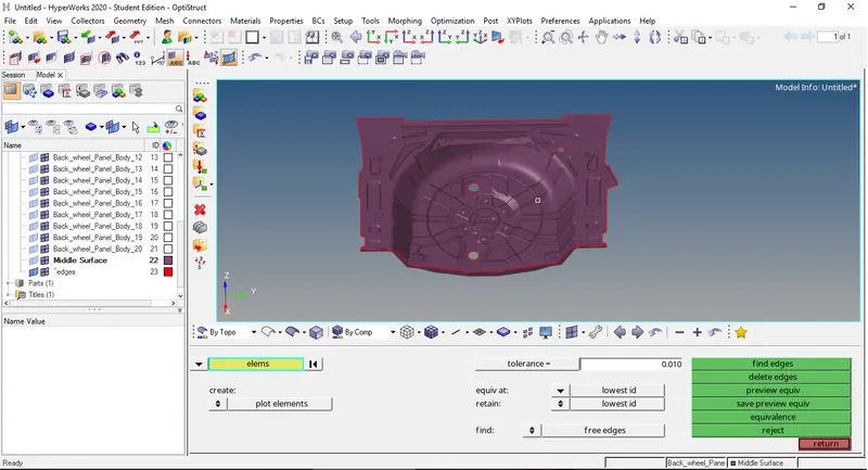
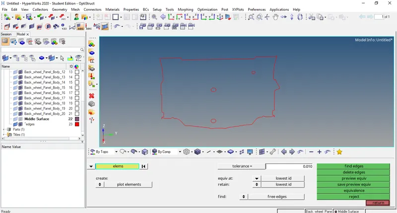
pictures representing the use of edge option to ensure the connectivity between the elements.
- In the next step assigned thickness of 0.75mm to all the elements.
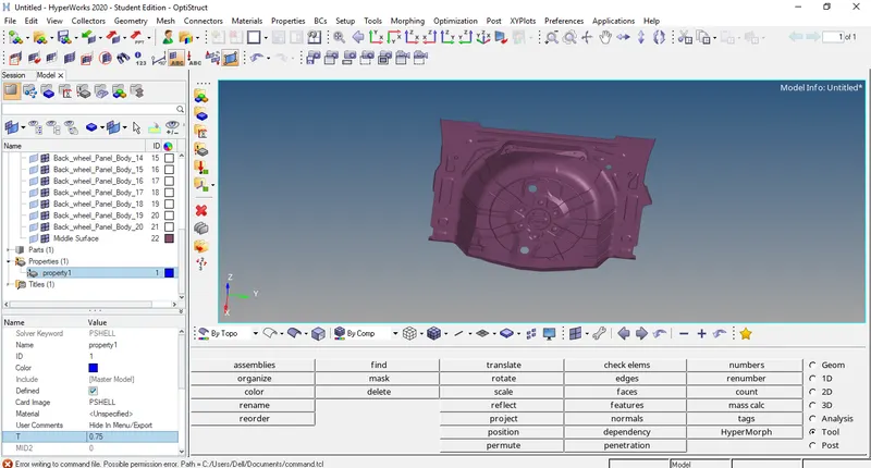
picture representing the property created in the tab area for assigning thickness to the elements.
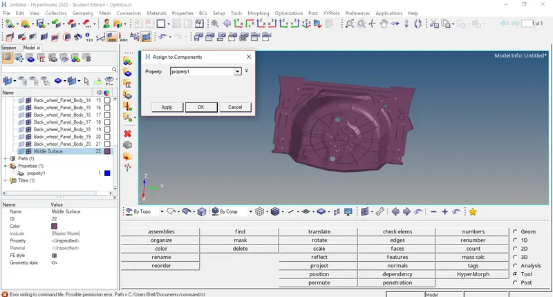
picture representing the property assigned the elements.
- In the next step to ensure the property assigned to the elements selected the "by prop" in the element color code.
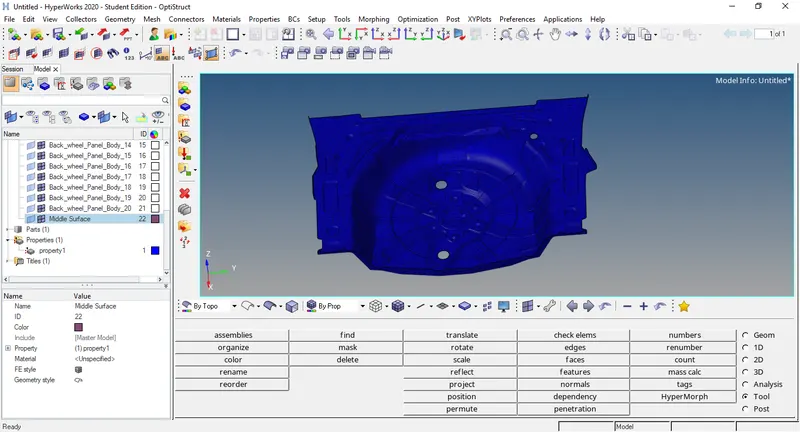
picture representing the color of elements changes when selected the by prop in the color code this ensures property is assigned.
Result - The result and learning outcomes from the model is as below -:
- Done manual geometry clean up un the parent geometry as well as on the midsurface.
- Automidsurface extraction option used to extract the midsurface.
- Meshed the whole component by using the automesh option.
- All elements passed the qulaity parmaters.
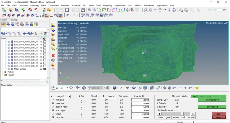
Picture representing all elements passed the quality parametrs.
- Assigned thickness to the elements.