2D Meshing of the Automotive Door Trim Using Hypermesh workbench
Aim:
To check the geometrical error of the component and Extract the Mid Surface of the given Door model and to do the 2D meshing for the component considering given quality criteria.
Abstract:
The door trim panels are key components making up the interior space of a vehicle. The main materials used include kenaf, which grows year round and has excellent CO2 absorbing properties, and plant-derived plastic, making them environmentally friendly as well.Door panels serve as an interface between the interior of the car and the inner workings of the door, and between vehicle occupants and the door. They are expected to meet a variety of design specifications regarding safety, aesthetics, and functionality. In addition, they are expected to continue the material theme of the dashboard and pillars while concealing intricate electrical and mechanical components for operating locks, windows, and other features. The door panel has evolved from a simple two-part system of latch and simple winding mechanism to a more sophisticated enclosure. Doors currently have an inner full-width panel consisting of electronic windows, central locking system, and speakers. These panels typically consist of a foamed core covered with either textiles or plastics.
Introduction of Finite Element Analysis:
- The Finite Element Analysis (FEA) is a numerical method for solving problems of engineering and mathematical physics.
- Useful for problems with complicated geometries, loadings, and material properties where analytical solutions can not be obtained.
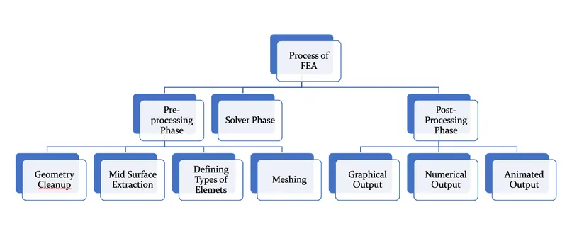
- Introduction to Meshing
1.1 What is Descritization??
Model the componet by dividing it into an equivalent system of many smaller bodies or units (finite elements) interconnected at points common to two or more elements (nodes or nodal points) and/or boundary lines and/or surfaces.
1.2 Why Do we Carry out Meshing?
Basic theme of FEA is to make calculation at limited number of points and then interpolate the results for entire domain.Any Continues object has infinite degrees of freedom and its just not possible to solve the problem in this format.Finite Element method reduces degrees of freedom from infinite to finite with the Help of Descritization i.e Meshing.
Types of Finite Elements:
There are 3 types of Element Namely 1D,2D and 3D Element.
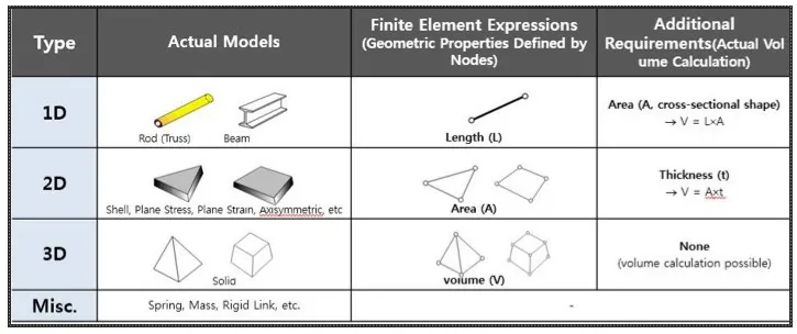
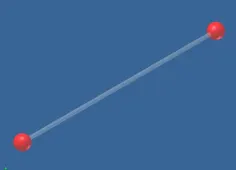
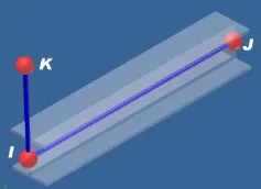
- 1D Element:
It is used for the geometry having one of the dimensions are very large compared to the rest two. Shape of the 1D Element is line.
Example:Beam Element,Truss Element
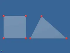
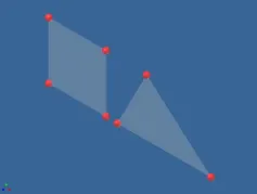
- 2D Element:
It is used for the geometry having two of the dimensions are large compared to the third dimension.2D Meshing is carried out on the midsurface of the part.
Why 2D Meshing is Carried out on the Mid Surface?
Mathematically the Element thickness specified by the user is assigned half on element top and half on bottom side.Hence in order to represent the geometry appropriately it is necessary to extract mid surface and then mesh on the mid surface.
Example:All sheett metal Componets,Plastic Components.
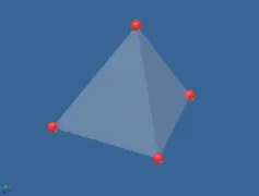
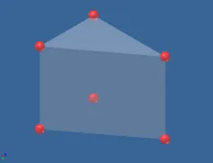
- 3D Element:
It is used when all the three dimension are comparable.
Example:Transmission Casing,Intake manifold,Connectong Rod,Clutch Housing etc
Given Quality Criteria:
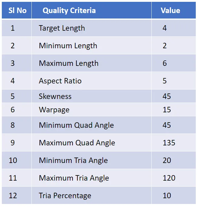
Overview on given Quality Parameters :
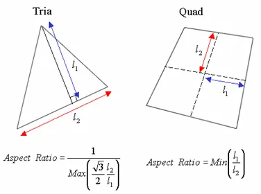
- Aspect Ratio:
The ratio between largest and smallest characteristic dimension of an element is known as the Aspect Ratio.Large aspect ratios increase the inaccuracy of the finite element representation and have a detrimental effect on convergence of Finite Element Solutions.
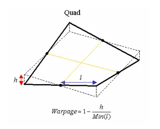
- Warpage:
The warpage of the quadrilateral elements is defined as the deviation from a best-fit plane that contains the element. It is not always a case to define a plane with 4 nodes. Therefore, a node of the quadrilateral element may be formed outside of a plane.The warpage is a measurement how this node has been deviated, and as it gets closer to 0, the element become more planar.
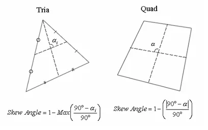
- Skewness:
Skewness is the Angular Measure of Element quality with respect to the Angles of Ideal Element Types.It is one of the Primary Qualities Measures of FE Mesh. Skewness determines how close to ideal (i.e., equilateral or equi-angular) a face or cell is.
Procedure:
1) Importing of the .IGS File of the Car Door in to the hypermesh WorkBench.
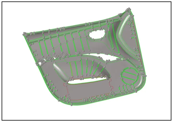
2)Geometrical Cleanup and Topology
- Check all the geometry errors in the model
- Fill all the missing Surfaces, free edges in the geometry.
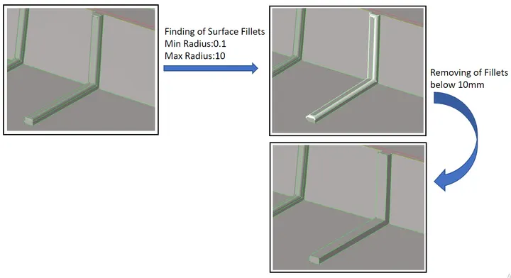
- Remove the Surface Fillets which will fail for Minimum Length Quality.
- Use the Defeature panel to find and delete pinholes, fillets on surfaces and surface edges, and duplicate surfaces. Each of the subpanels allows you to manually select the feature that you wish to delete, but also supports a three-step process that can locate such features for you.
- To delete the Surface Fillets which is too less, use the Surface Fillets Sub Panel and remove surface fillets.
- we have to identify fillets based on radius, because fillets are always uniform arcs. You can also select a fillet by picking one of the edges that it connects. Once found, fillets can be removed using tools that display automatically after the find process.
- Refer the Pictures below for the Process:

- Toggle all the Unnecessory Lines on the surfaces which leads to bad mesh Quality.
- Replace the points wherever the needed.
2) Extraction of Mid Surface
Midsurface modeling is a technique for creating a simplified shell representation of a solid model. Midsurface modeling can reduce the computational expense of analyzing a complete solid model when a shell model with a defined thickness and fewer details is suitable for the required analysis.
Reasons to use the Mid Surface Shell MEsh for thin Walled Componets:
- Accuracy of the end result can be way off with solid mesh elements.
- The solid mesh approach, which needs 3 to 4 elements across the thickness, results in huge amount of elements and long running times.
- Meshing unpleasent geometry with solid mesh elements needs Geometry Cleanup Too.
- Post processing of huge amount of solid element simulations takes lot of time.
- The shell mesh approach creates a fast running accurate simulations.
Use the Midsurface panel under Geometry to extract the midsurface representation of a solid part or to generate a finite element shell representation of a solid geometry.The Midsurface panel can be used to extract the midsurface of sheet metal stampings, molded plastic parts with ribs, and other parts that have thickness clearly smaller than width and length.
Mid Suerface Panel Consists of Five Sub Panel as listed below:
- Auto Mid Surface Tool
Use the Auto Midsurface tool to extend and modify midsurfaces. - Intrim edit Tool
Use the Interim Edit tools to modify plates, base surfaces, and collapsed lines on the midsurface. - Final edit Tool
Use the Final Edit tools repair surfaces, modify targets, and imprint surfaces after the midsurface has been extracted and you do not need to make further changes that require the midsurface to be re-extracted. - Review Thickness Tool
Use the Review Thickness tool to review the thickness of surfaces (including midsurfaces) and assign new fixed, uniform thicknesses to surfaces. - Sort tool
Use the Sort tool to manually sort midsurfaces after extraction.
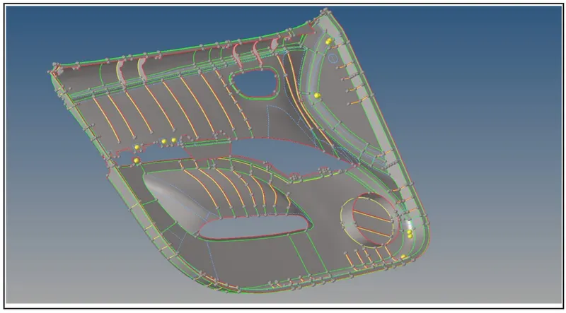
In this Model we have taken the Manual Mid Surface as the Door Component is of Plastic and has varying Thickness.
- Measure the thickness along the Component and Note down the thickness.
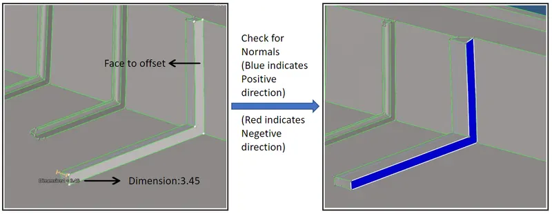
- Select the Surfaces to offset and give the Value.
- We can take the manual mid surface in various method like Duplicate and Translate the Surfaces to the Specific distance ,Duplicate the Surface and Offset to the half of the thickness.
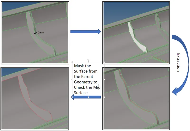
- Mid Surface of the Rib with uniform thickness can be taken in Final Edit tool by selecting the two Side surface of the ribs and the Mid surface of the Ribs will be generate .
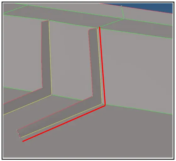
- Mid surface of the all the ribs muct be extend upto its base surface.
in this mOdel We Peofrmed Offset Command to take the Mid Surface of the Component.
- Go to Surface Edit Panel(Shift+F9)
- in the Offset Sub Panel,Select the faces to Offset.
- Check for the Normals.

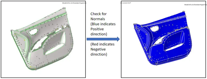
4.Click on the Offset Button to Perform the operation and Mis surface of the selected faces is as shown below.
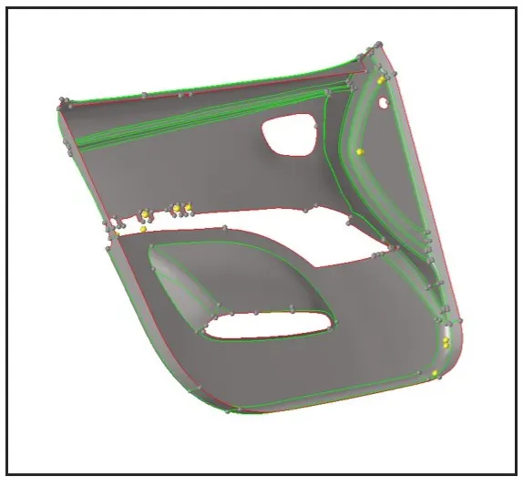
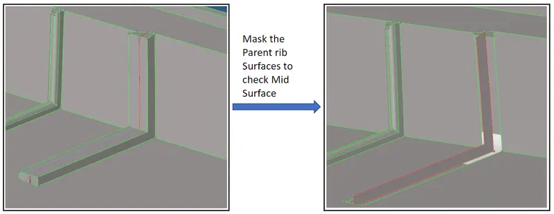
5.Mid Surfaces of the rib also taken in the similar way as shown below.
Note:All the Ribs Muct be Extended upto Base Surfaces which will be indicates in triple Cons as shown in figure below.
6.Mid Surface of the ribs with Symetrical Surfaces can be taken using Surface Pair Sub panel in the Mid surface panel by selecting the two Sides of the ribs.
7.Thus the Mid Surface of the Whole Component is taken and shown in figure below
3) Geometrical Clean up and Topology
- Check all the geometry errors in the model
- Mid Surface should be exact replica of the Parent Model.
- Fill all the missing Surfaces,free edges in the geometry.
4)Meshing
Meshing is an integral part of the engineering simulation process where complex geometries are divided into simple elements that can be used as discrete local approximations of the larger domain. The mesh influences the accuracy, convergence and speed of the simulation.
Rules before starting meshing
- The mesh should look rather smooth and regular.We should keep in mind that the analysis is based on our Mesh Flow and mesh quality is the key.
- Use the simplest element type suited for the problem
- Try to keep mesh related uncertainties to a minimum as much as possible.
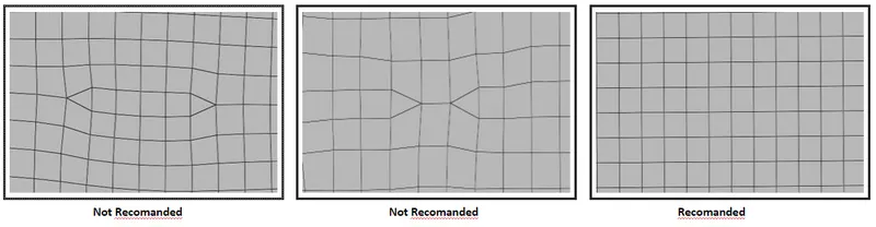
- Opposite trias should be avoided.
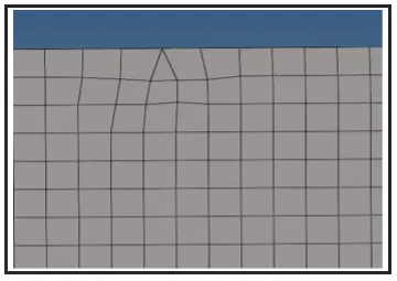
- No trias should be there in the free edges.
- Rotational Quad should be avoided.
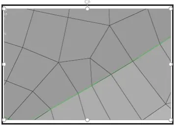
- No trias should share a boundry with features line.
- Use Mixed type Elements for irregular shapeed surfaces and quad only for rectangular/square shaped surfaces.
- No mesh transition on constant transition on constant radius fillets / curvatures.
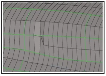
Now Let us Study How To Mwsh the Given Component in Hypermesh considering all the Above explained Rules.
Use the Automesh panel to generate a mesh of plate elements using surface geometry or existing shell elements to define the mesh area.
Set the options in the panel in any order that you feel comfortable using. Moving from subpanel to subpanel will not cause you to lose work. When you are finished making all your selections, click mesh to start the meshing process.
- Set the panel mode by selecting the appropriate subpanel.

- Select the meshing method by setting the entity selector to surfs or elems.
- Make the required element criteria settings by Selecting Preferences>Criteria File Settings.
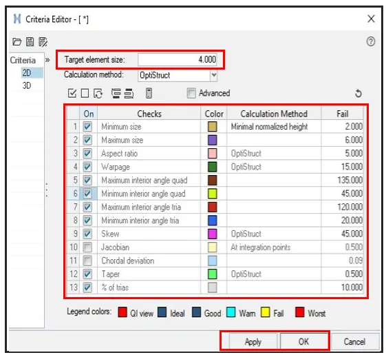
- Set any algorithm options.
- Select the area to be meshed using the entity selector and any extended selection methods.
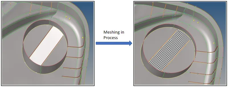
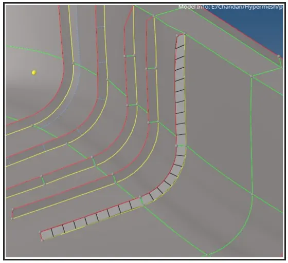
- In Case of Trias Occur in the Free Edges,Either We can Drag the tria Out side or We can keep the Trias in the flat Surfaces.
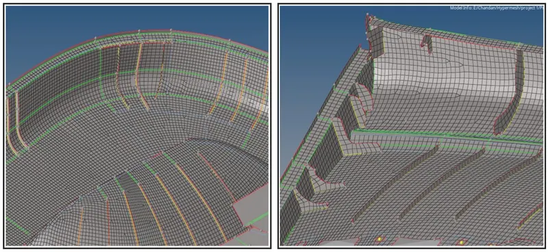
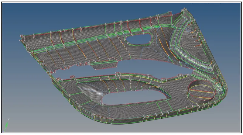
- Use the Cleanup tools in the Quality Index Panel to get the Good Mesh flow.
5)Checking for Quality Criteria
Use the Quality Index panel to check the quality of the meshed shell in the model.Cleaup tools in the secondary panel is helpfull where you can manually alter the placement of nodes to improve local quality.

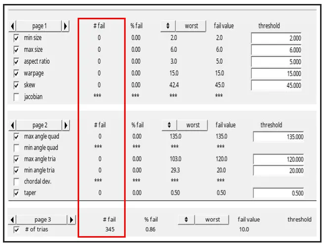
Criteria settings are stored and retrieved using a criteria file. You can save the results from the Quality Index (QI) panel to a summary file.
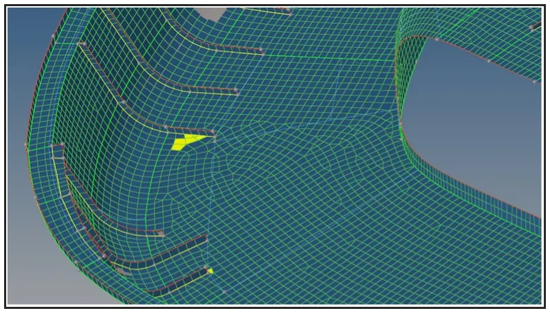
- All the Elements which are failing for Quality Criteria must be recreated,Remeshed and Smoothing to be done .
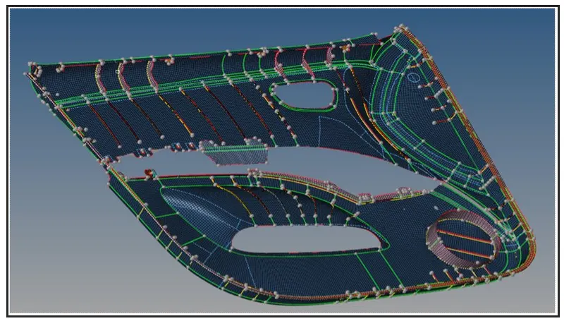
- Thus The Meshing is Complted and All the Elements are Passing for given quality criteria and have the good tria percentage of 0.86% as shown below.
6)Assigning the Thickness to the 2D Shell Mesh
- Once the Meshing of the Component is done we need to assign the thickness to the shell element.
- Create the Seperate Component for Each Value of thickness as shown below.
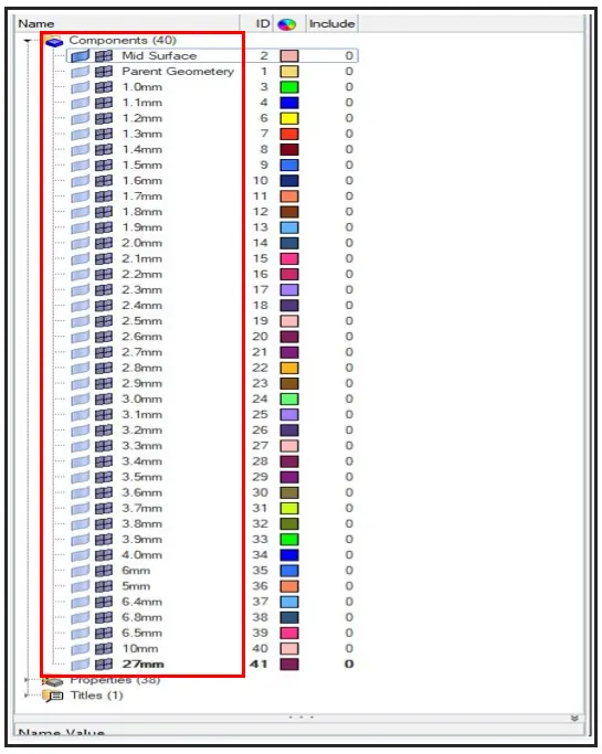
- Create the Property for all the Required thickness and Assign it to the Respective Component.
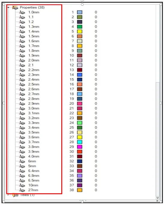
Once the Property Card is Created,Assign the Same to the Respective Component By Right Clicking on the Component and Selecting Assign Command.
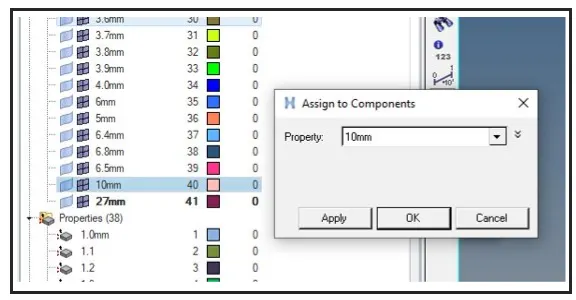
- Once after the assigning the Thickness to the Component,Measure the Thickness of the Component from the Parent Geometry.
- Use the Organize Panel(Shift+F11) to moce the Elements,Surfaces from one Component to another.

- Select the Elements from the Geometry and Move the Elements to the respective Component based on its thickness as shown in the picture below.
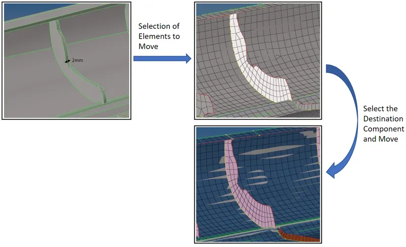
Thus The Procedure is repeated for every Ribs and the Surfaces and Elements should be well organised with respect to its thickness as same in the Parent Geomtery.
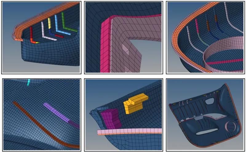
By enabling the 2D traditional and Detailed Element Representation,We can Visualize the 2D Shell elements into 3D As shown in the picture below.
Result:
Meshing of the Given Door trim component is Done and all the Elements are qualifying given quality Criteria and also all the rules for meshing is followed and have the trai Percentage of 0.86%
Learning Oucomes:
- Able to fix geometrical Errors and Geometric Cleanup of the Component.
- Able to Creating and extracting of Mid Surface from the Parent Geomtery of the Component.
- Defeaturing of the Component
- Meshing of the Component considering all given quality Criteria.
- Removing Trias and Rotating Quads and trai Management.
Conclusion:
In the above Model we can conclude that the Meshing process is very similar to the any complex geometry and it is observd that Before meshing we need to observe and study the model carefully as it has many missout surfaces and free edges.While Meshing the any CAE Engineer should be aware of Tria managment and its results when the Nodal force has Introduced all around to analize the Model and all the Elements should meets the given quality criteria .Thus the Car Door model has been meshed properly and can be given for next Solver Process.