Meshing of Door Panel
AIM:
To extract the midsurface for the given component and mesh it with given quality criteria.
METHODOLOGY:
- Importing the model.
- Cleaning the imported geometry.
- Extracting the midsurface for the geometry.
- Meshing the surfaces with given quality criteria.
INTRODUCTION:
A side door panel is made up of plastic coated with leather in some cases. It contains lots of mechanisms in it like sliding window buttons, speakers, holders etc.
PROCEDURE:
Importing:
- Click on open, open the folder in which file is located.
- Click on ‘open’.
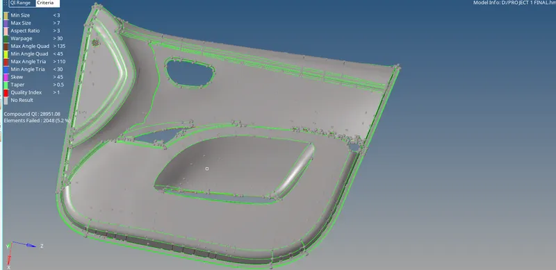
Figure-1(model import)
Clean up:
- Delete all the solids of the geometry.
- Clean up the each component with different options like
- Toggle
- Add / remove point
- Split surf node
- Split surf line

Figure-2( cleaning tools)
Midsurface:
- Measure the distance between two points at different location and note it.
- Go to surface edit panel, select ‘offset’.
- Select the surface to be offset by duplicating the surface in current component.
- Add the value to be offset and check the vector normal.
- If right click on ‘offset’ else reverse the normal and click offset.
- Separate the components by measuring the thickness values.
- For varying thickness components create a middle line.
- Go to line panel, select ‘midline’.
- Select two lines and click on ‘create.
- Project those line onto the surface by duplicating them.
- Create the surfaces by those lines.
- All the lines should be connected to the main body.
- Join the surfaces by extending or trimming the surfaces.
- Organise the surfaces according to their thickness value.
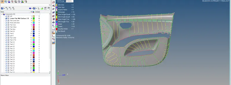
Figure-3(midsurface)
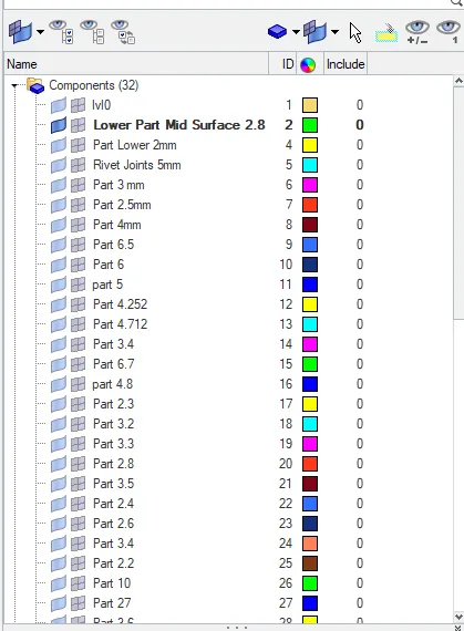
Figure-4(components with thickness value)
Meshing:
- Set the criteria in ‘criteria editor’ module.
- Set all the values and click on ‘apply’ and ‘okay’.
- Select the each surface and mesh it.
- Set the element size as ‘4’ and mesh the surface.
- If any errors is visible go to ‘quality index’ panel.
- Select the appropriate option to solve the error.
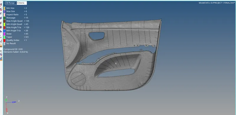 .
.
Figure-5(meshed model)

Figure-6(quality index panel)
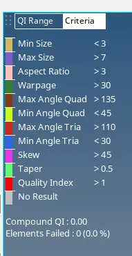
Figure-7(zero elements failed)
Assign the thickness:
- Create a property card in the tool bar.
- Set the thickness in the property card and name as per component card name.
- Left click on component card and select the ‘assign’.
- Select the appropriate property card name and click on apply.
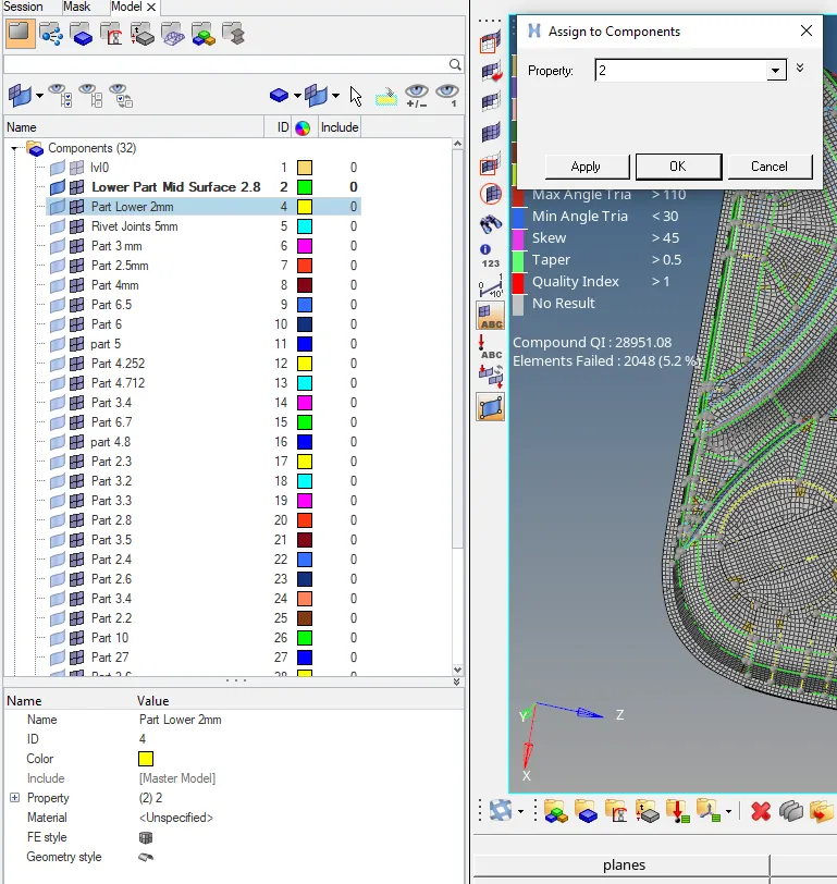
Figure-8(thickness assigning)
Learning outcome:
All the options used previously is recollected.
RESULT:
The given model is extracted the midsurfaces and meshed the model with given quality criteria.
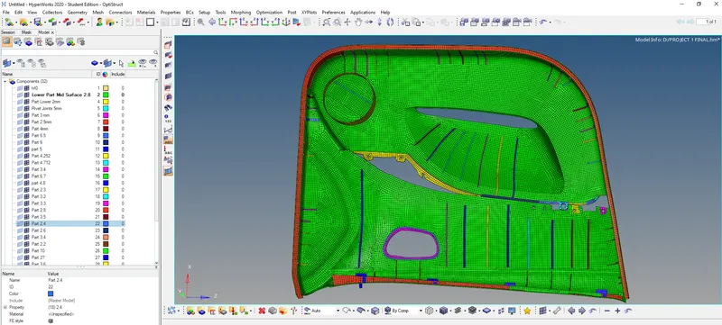
Figure-9(Final model)
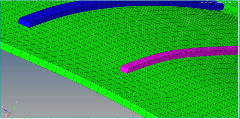
Figure-10(assigned thickness)