Detailed Meshing of an automobile side door using Hypermesh
Project Link
https://drive.google.com/open?id=10y8ASep_Hlx5i4DV6TVPxYA3imfSwPeT
Objective:
- Extract the midsurface of the given component as per given quality criteria
|
S.N |
Quality Criteria |
Value |
|
1 |
Aspect Ratio |
5 |
|
2 |
Skewness |
45 |
|
3 |
Warping |
15 |
|
4 |
Taper |
0.5 |
|
5 |
Min. Length |
2mm |
|
6 |
Max. Length |
6mm |
|
7 |
Min angle Quad |
45 |
|
8 |
Max angle Quad |
135 |
|
9 |
Min angle Tria |
20 |
|
Max angle Tria |
120 |
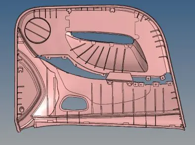
- Generate the 2D mesh
- Generate property file of different thickness and assign it individually
Procedure:
Step 1 – Preparing Geometry
- Import the geometry Side door in Hypermesh
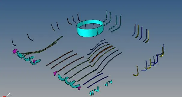
- Separate two components as shown below
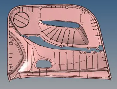
Component 1
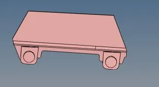
Component 2
- Since the both the component has variable thickness, we need to extract midsurface manually
- To extract midsurface manually follow the below procedure
- Measure distance between two surfaces
- Go to Surface Edit -> offset -> select surface -> check direction normal -> give the mid distance -> offset.
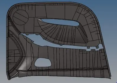
- Repeat this step for all the surface and generate a uniform midsurface of the whole model
- There are ribs in the model which needs to connect to the base surface. For that follow one of the following step
- Surface edit -> extend -> select surface to be extended -> select base surface -> extend
- Surface -> Drag along vector -> select the base line along ribs -> give distance -> MMB. No surface edit -> trim surface with surface -> select both the surface -> trim. Delete additional surfaces
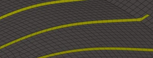
- The Yellow line should appear at the interjection of ribs and base surface.
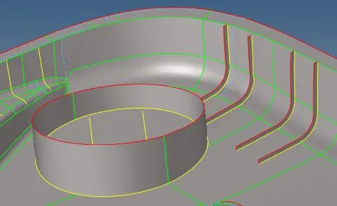
- Once all the midsurface are extracted, perform geometry cleanup using one of the following options
- Quick edit -> toggle line -> to suppress unwanted edges.
- Quick edit -> Split surface with nodes (to divide the surface into smaller ones)
- Quick edit -> Split surface with node and line ( to divide the surface into smaller ones)
- Quick edit -> replace point (to stick gaps between surfaces and remove red lines)
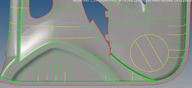
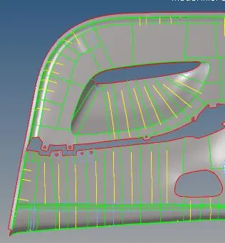
- Manually check whole geometry to confirm geometry cleanup is successful
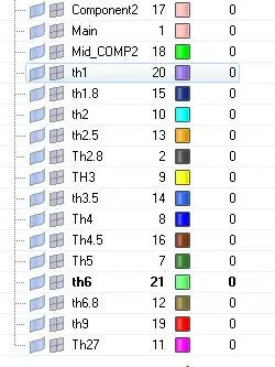
- Divide the whole model using different component and name them on the basis of it thickness. Allocate each surface to corresponding thickness component
Step 2 – Generate Mesh
- Since there are different surface along different planes, extra care needs to be taken while meshing
- To generate mesh
2D -> automesh -> select surface -> element size = 4 -> element type = mixed -> mesh
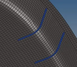
- First of all mesh the ribs properly
- Now start selecting adjoining surface one by one
- Check for quality using
Tools -> check elems -> check quality parameters as per given quality criteria
- Repair failed element using one of the following methods
- 2D -> quality index -> cleanup tools -> element optimize
- 2D -> quality index -> cleanup tools -> place nodes
- 2D -> edit elements -> combine / split/ create
- Repeat this steps for all surfaces of the model and generate a uniform 2D mesh satisfying given quality criteria.
- Make sure there is proper mesh connectivity between different parts and no of trias are as low as possible.
Step 3 – Assign thickness to the individual component
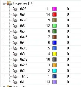
- Create different property file with different thickness and colour code it similar to its component colour for simplification
- Assign these properties to respective component
- Check using display 2D mesh option to check for the thickness in mesh
Results:
Below images show the mesh of whole model
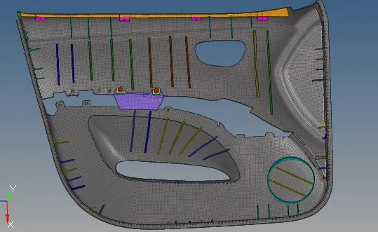
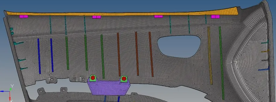
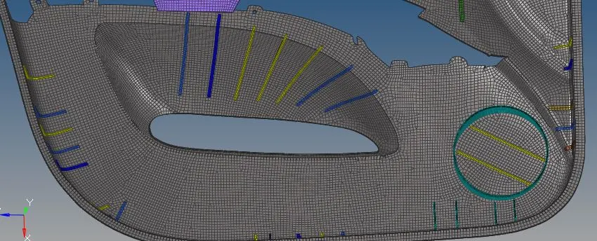
No of Nodes: 38756
No of Elements: 38364
No of quads: 37329 (97.302 %)
No of trias: 1035 (2.698 %)
|
S.N |
Quality Criteria |
Value |
No of failed elements |
% of failed elements |
|
1 |
Aspect Ratio |
5 |
0 |
0 |
|
2 |
Skewness |
45 |
2 |
0 |
|
3 |
Warping |
15 |
1 |
0 |
|
4 |
Taper |
0.5 |
1 |
0 |
|
5 |
Min. Length |
2mm |
3 |
0 |
|
6 |
Max. Length |
6mm |
0 |
0 |
|
7 |
Min angle Quad |
45 |
2 |
0 |
|
8 |
Max angle Quad |
135 |
2 |
0 |
|
9 |
Min angle Tria |
20 |
0 |
0 |
|
Max angle Tria |
120 |
0 |
0 |
Note: all the failed elements are in component 2, due to a very high difference in thickness for smaller cross section.
Conclusion:
This activity helped us understand the basic procedure to mesh the component with variable thickness using manual midsurfacing and manual meshing and controlling the mesh quality for such complicated geometry.