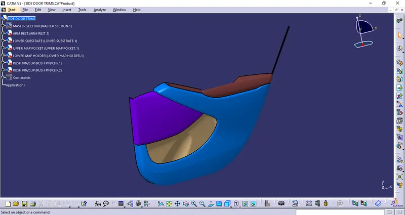
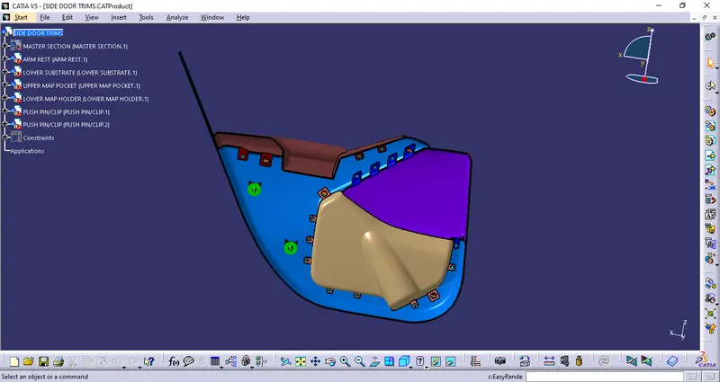
Week 12- Final project
Final project
Aim
To develop a Door Trim panel CAD model considering following inputs as like in OEM and tier1 companies.
- Class A surface
- Nominal thickness : Refer master sections
- Attachment strategy :
- Find a attachment strategy for the door panel complete work.
- Use Push pin with Dog house for Lower substrate – Door panel attachment.
- Use heat stakes for part to part attachment.
Software used
- CATIA V5
Indroduction
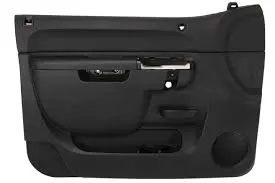
Door Trim Panel
Door panels serve as an interface between the interior of the car and the inner workings of the door, and between vehicle occupants and the door. They are expected to meet a variety of design specifications regarding safety, aesthetics, and functionality. In addition, they are expected to continue the material theme of the dashboard and pillars while concealing intricate electrical and mechanical components for operating locks, windows, and other features. The door panel has evolved from a simple two-part system of latch and simple winding mechanism to a more sophisticated enclosure. Doors currently have an inner full-width panel consisting of electronic windows, central locking system, and speakers. These panels typically consist of a foamed core covered with either textiles or plastics. Plastics is the core and soul of the door trim interior, one must have knowlege about the plastic being used and its cost associated with the molding and manufacturing.
Class-A surface:
The Class-A surface is the outermost surface of the plastic component which is also looks fine surface and it is the aesthetic surface that the designer creates as an input part for the design work.
Class-B surface:
The Class-B finish is a quality finish with only minimal imperfections. A Class-B finish is the most common finish for exterior surfaces. It is normally specified on surfaces such as external covers, panels, and parts that are fairly prominent.
Class-C surface:
The Class-C finish allows more imperfections than Class-A or Class-B. Class-C is often specified for interior surfaces not readily visible, surfaces that will be covered by another part when assembled, or surfaces which the Customer feels do not need to meet a high cosmetic finish.
Tooling Axis:
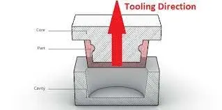
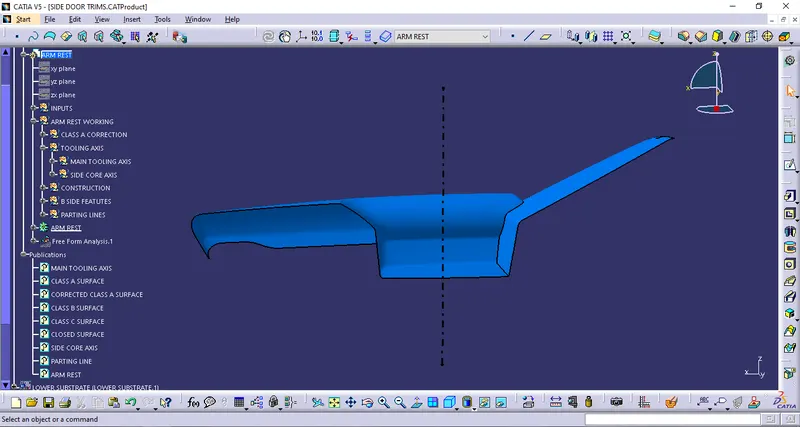
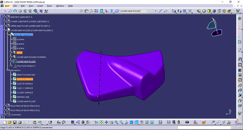
In Molding, machine arrangement is given to open the mold along a direction which is known as Tooling Direction. In other words. The mold is built from two separate halves (Core and Cavity) and tooling direction basically defines the direction of mold or core pulls apart.
Draft Analysis:
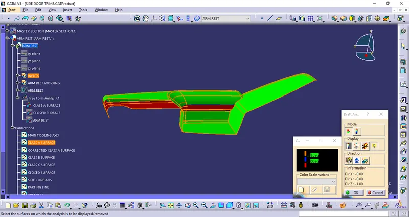
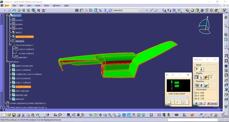
The Draft Analysis command enables you to detect if the part you drafted will be easily removed. This type of analysis is performed based on color ranges identifying zones on the analysed element where the deviation from the draft direction at any point, corresponds to specified values. Most parts or applications require minimum of 1/2 to 1 degree, however 3 degrees is widely accepted as the norm.

Design Methodology:
Components of Door Trim panel:
- Arm Rest
- Lower Substrate
- Upper Map Pocket
- Lower Map Holder
1.ARM REST
CLASS-A SURFACE
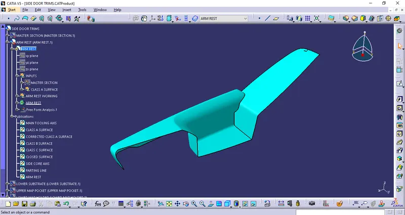
The given Class A Surface does not have proper surface continuity.
- Corrected Class-A Surface.
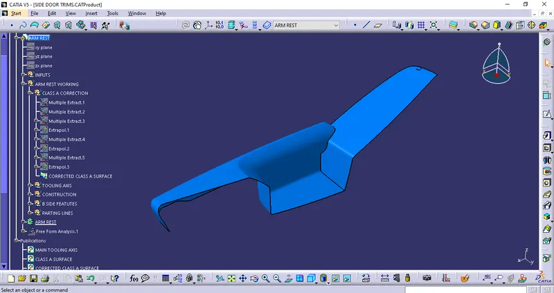
- Tooling Axis Creation.
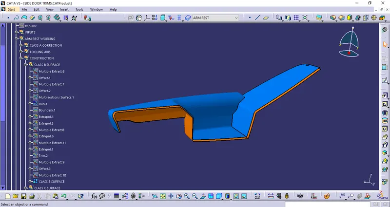
- Class-B Surface Creation.
- Class-C Surface Creation.
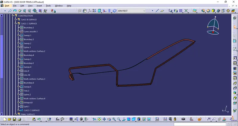
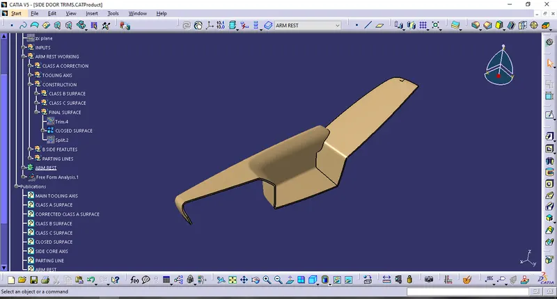
- Final Surface
The Class-A, Class-B and Class-C surfaces are joined together to form a closed surface.
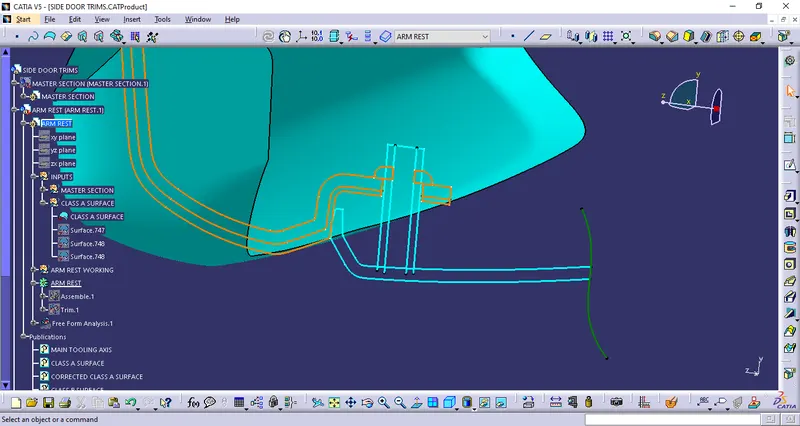
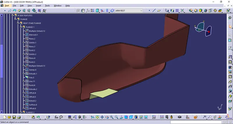
- Flange Creation.
Given master section
Flange Thickness : 2.5mm
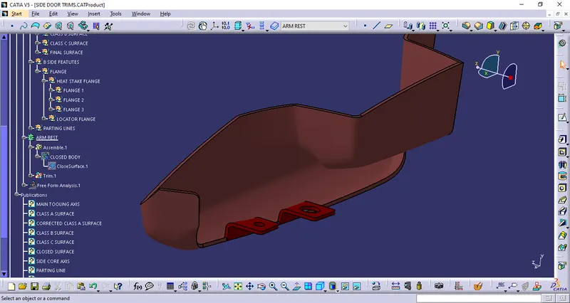
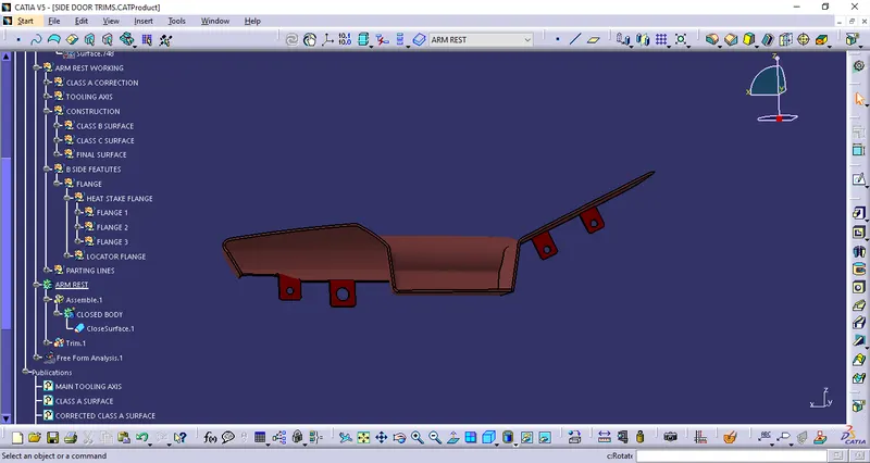
- Final Plastic Component.
Thickness : 2.5 mm
- Draft Analysis
Class-A Surface
Closed Body
2.LOWER SUBSTRATE
- Given Class-A Surface
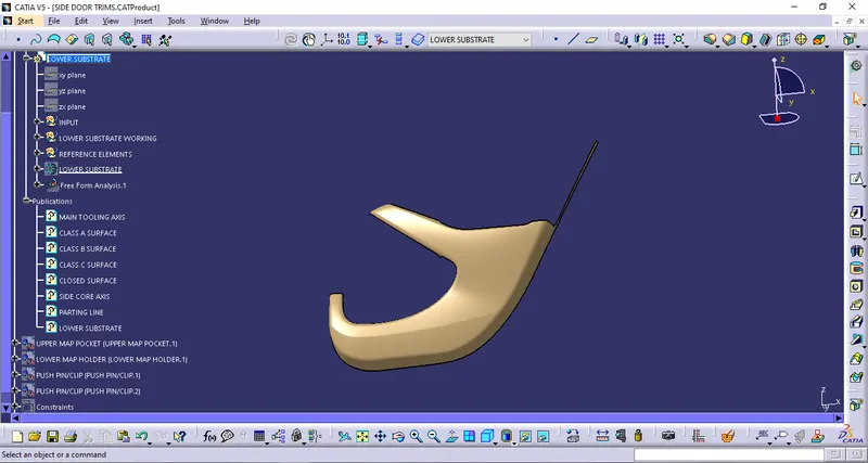
- Tooling Axis Creation.
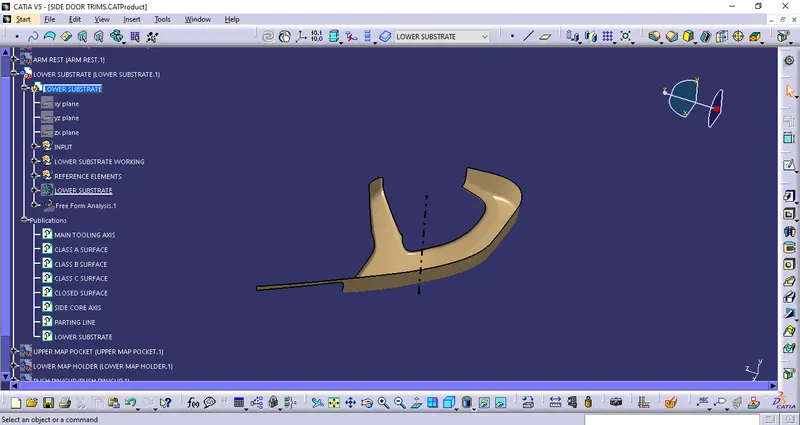
- Class-B Surface Creation.
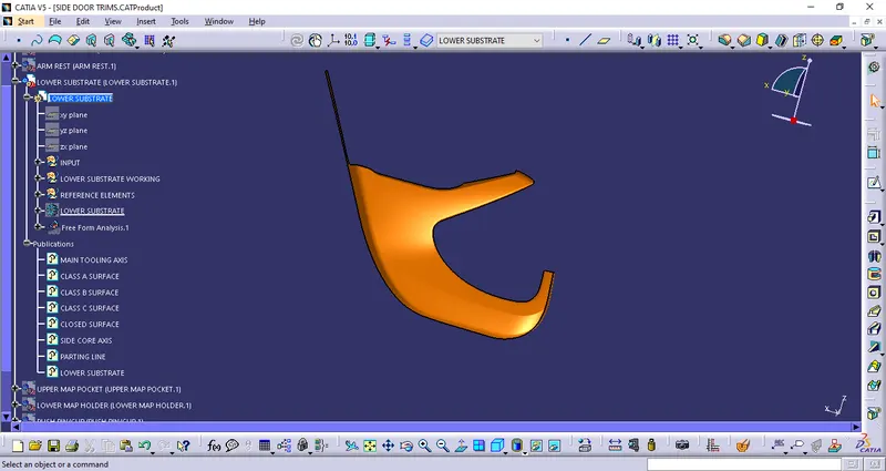
- Class-C Surface Creation.

- Final surface.
The Class-A, Class-B and Class-C surfaces are joined together to form a closed surface.
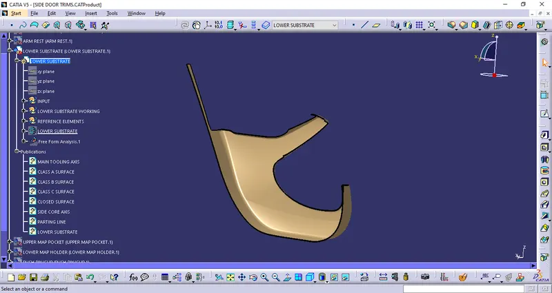
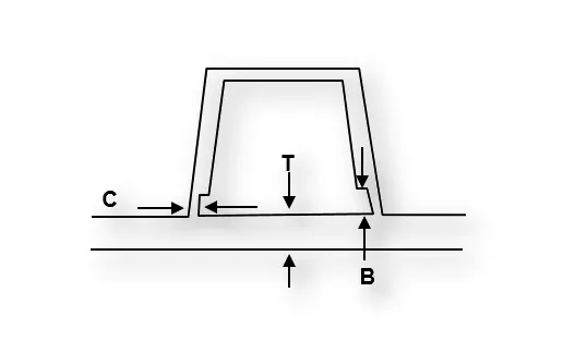
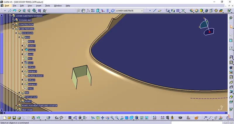
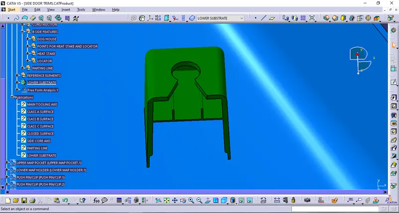
- Creation of Dog House.
General Guidlines for Dog House:
- "C" is where the doghouse contacts the backside of the surface.
-
Doghouse wall thickness at the intersection of the part wall ( C ) should be 40% or less than the main wall stock ( T ).
-
The height of ( B ) should be between 3.0 – 6.0 mm.
- Minimum Doghouse Width (X) for doghouses is 12 mm.
- Minimum Draft (D) for doghouse is 1.5 degree* to die draw.
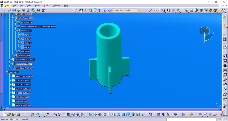
- Creation of Heat Stakes.
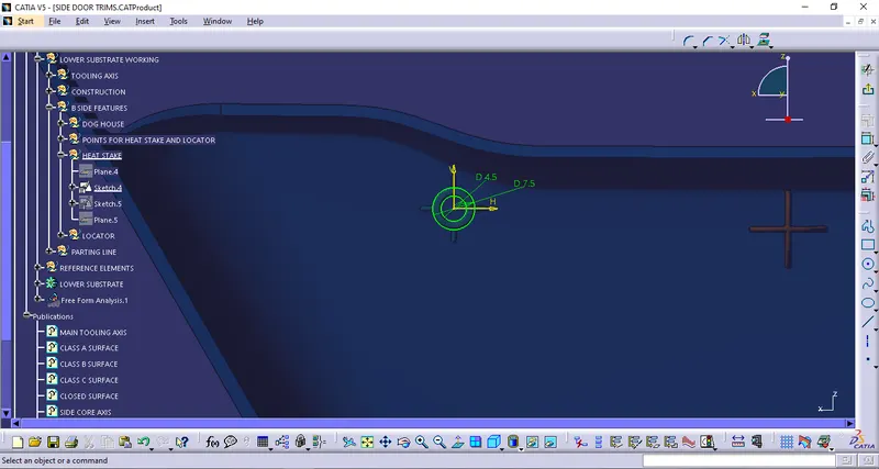
Thermal staking is an assembly method that uses the controlled melting and reforming of a plastic stud or boss to capture or lock another plastic or metal component of an assembly in place.
Guidelines for creating Heat stakes:
- Minimum 15 mmm gap between heat stakes.
- Maximun clearence with The counter clearence should be 0.5 mm.
- Maximum fillet radius be 0.25 mm..
- Draft : 0.5* per sides.
- Creation of locators.
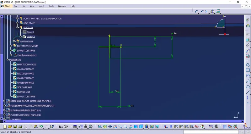
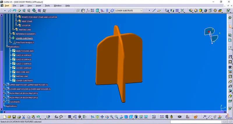
Locators are used to positioned the components in exact location and act as a guide for joining the two components.
Guidlines for Creating Locators:
- Draft : 0.5* per sides.
- Thickness - Tipically 40% wall thickness.
- Maximum fillet radius 0.25mm.
-
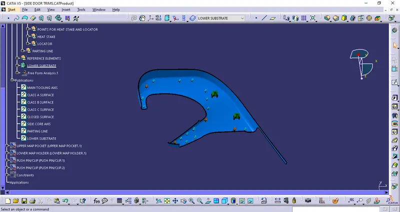
Final Plastic Component.
Thickness : 2.5 mm
- Draft Analysis.
Class-A Surface
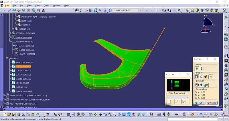
Closed Body
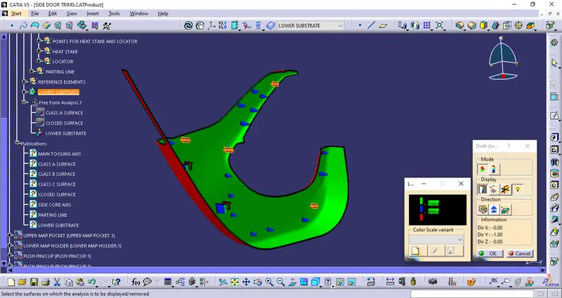
Dog House
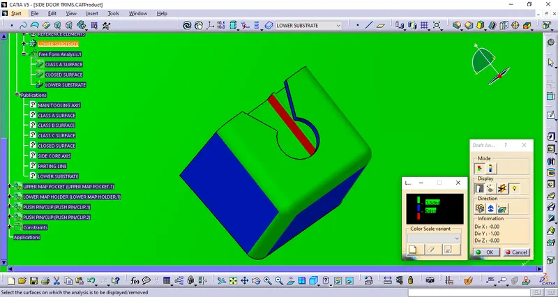
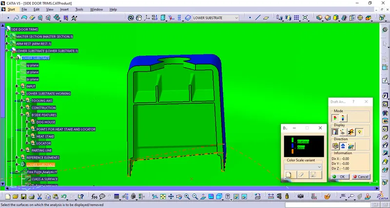
Heat Stakes
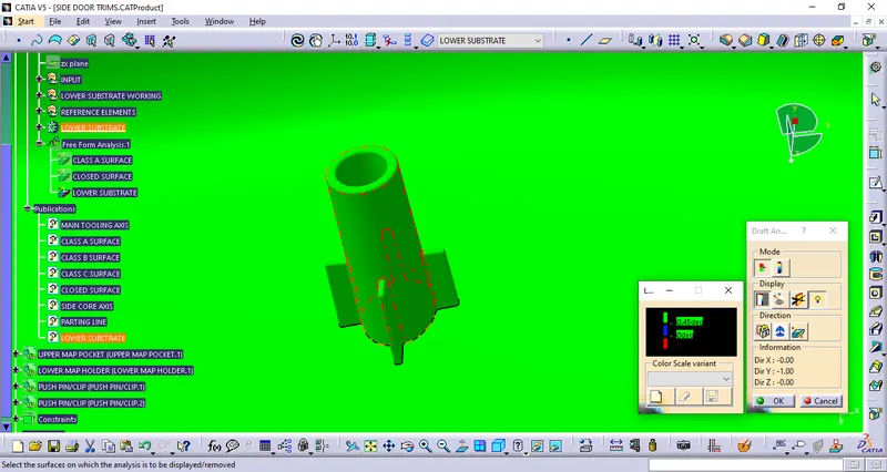
Locators
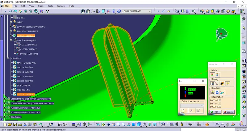
3.UPPER MAP POCKET
- Class-A Surface
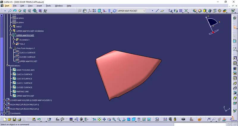
- Tooling Axis Creation.
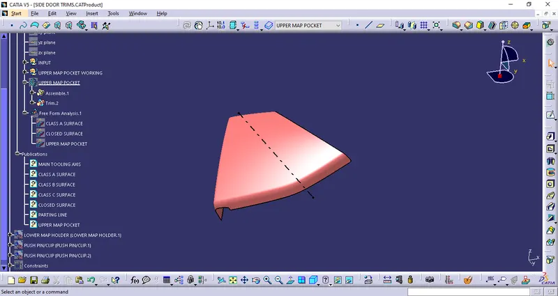
Class-B Surface Creation.
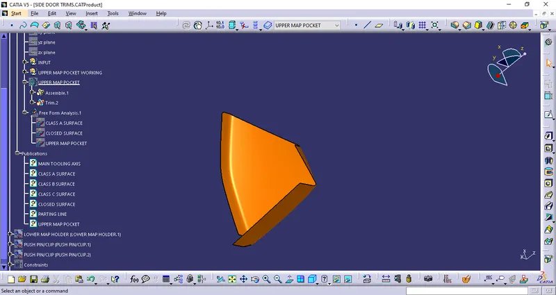
Class-C Surface Creation
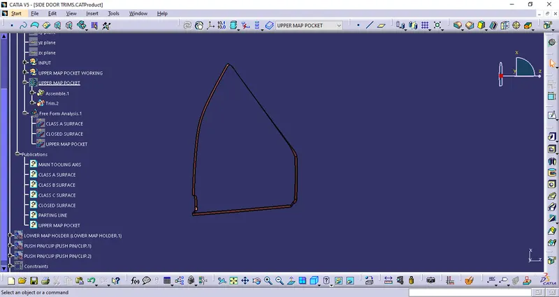
- Final surface.
The Class-A, Class-B and Class-C surfaces are joined together to form a closed surface.
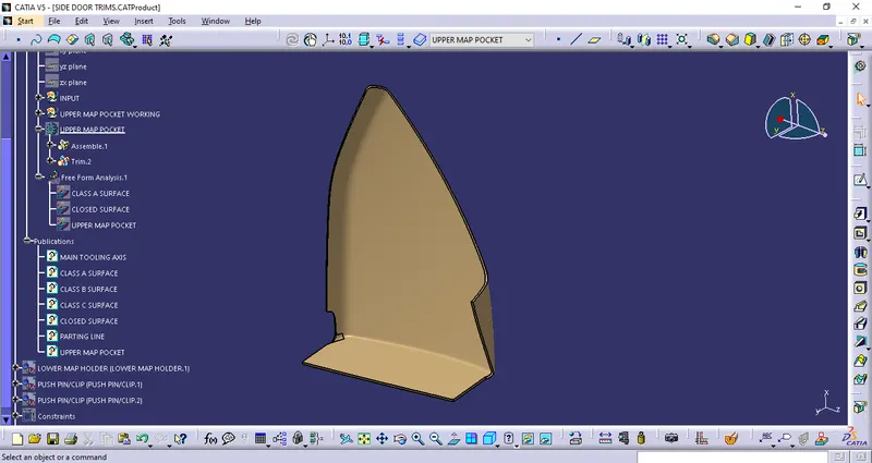
- Creation of Flanges.
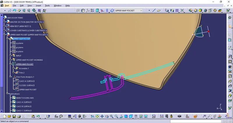
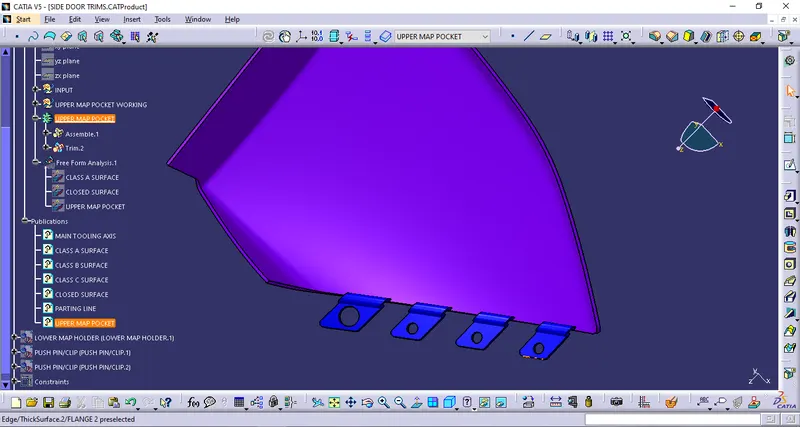
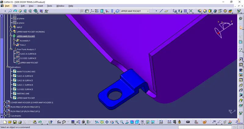
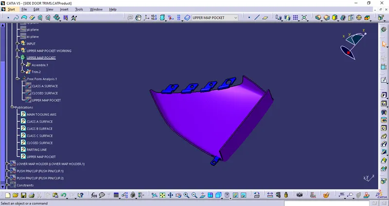
- Final Plastic Component.
Thickness : 2.5 mm
- Draft Analysis
Class-A Surface
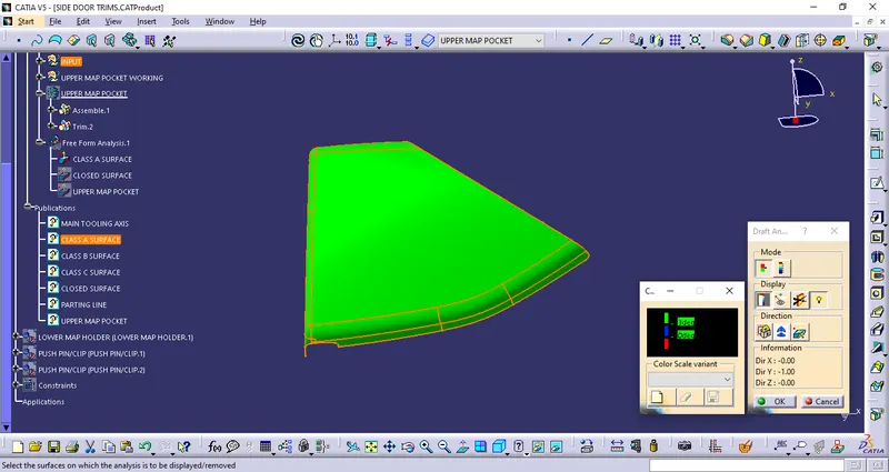
Closed Body
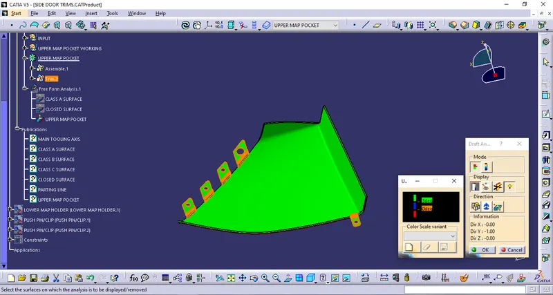
4.LOWER MAP HOLDER
Class-A Surface.
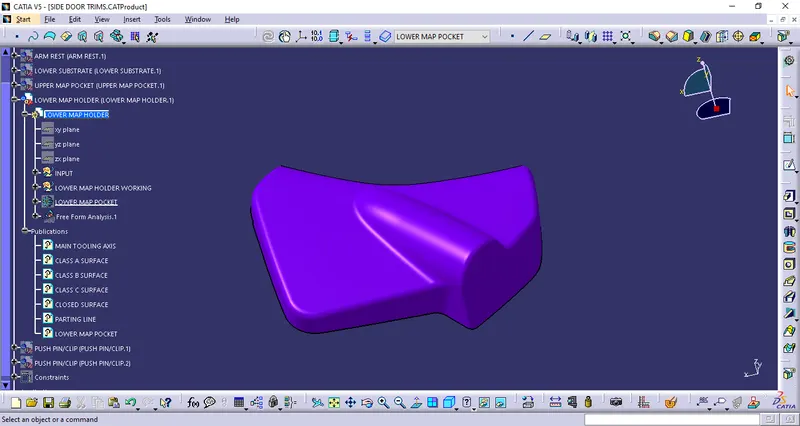
- Tooling Axis Creation.
Class-B Surface Creation.
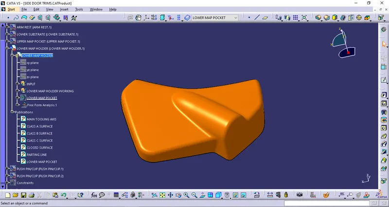
- Class-C Surface Creation.
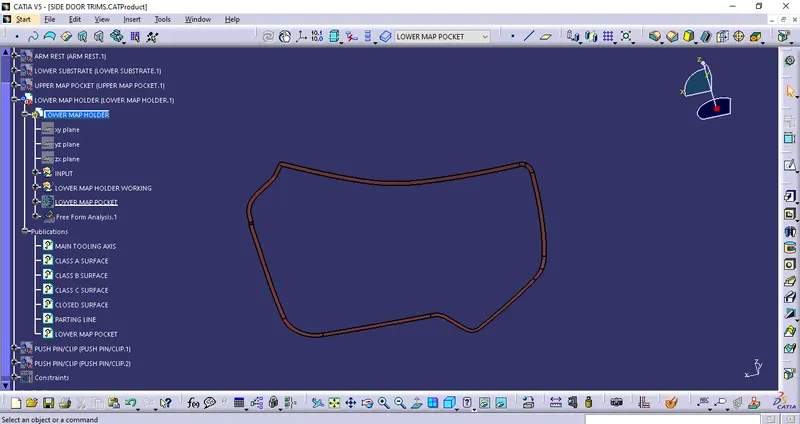
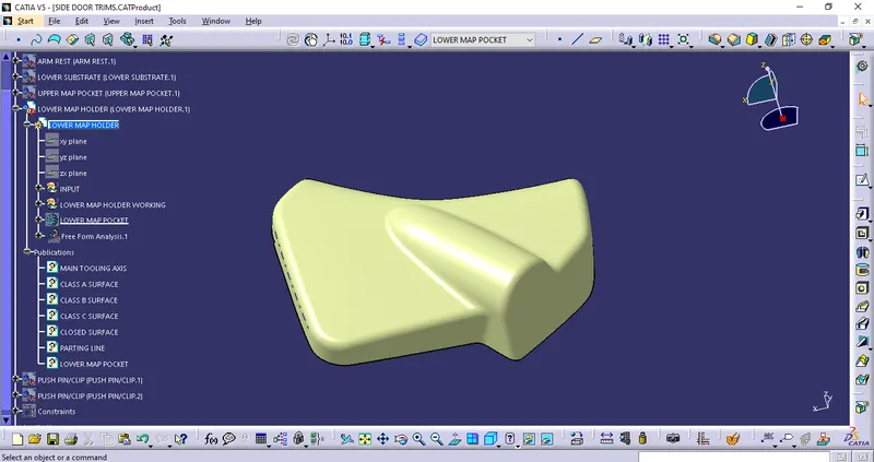
- Final surface.
The Class-A, Class-B and Class-C surfaces are joined together to form a closed surface.
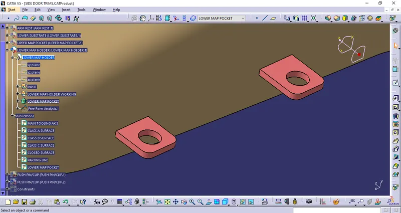
- Flange Creation.
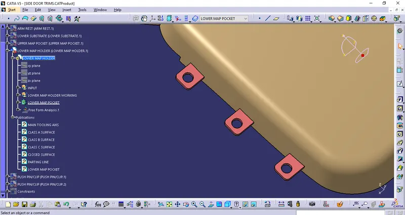
- Final Plastic Component.
Thickness : 2.5 mm
- Draft Analysis.
Class-A Surface
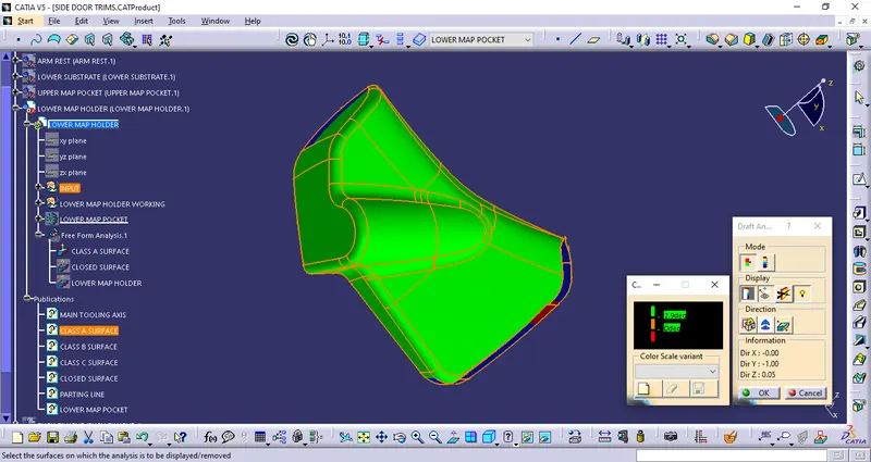
Closed Body
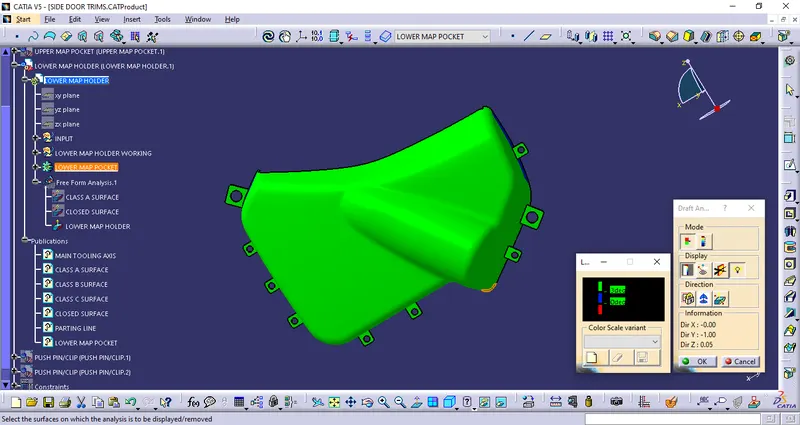
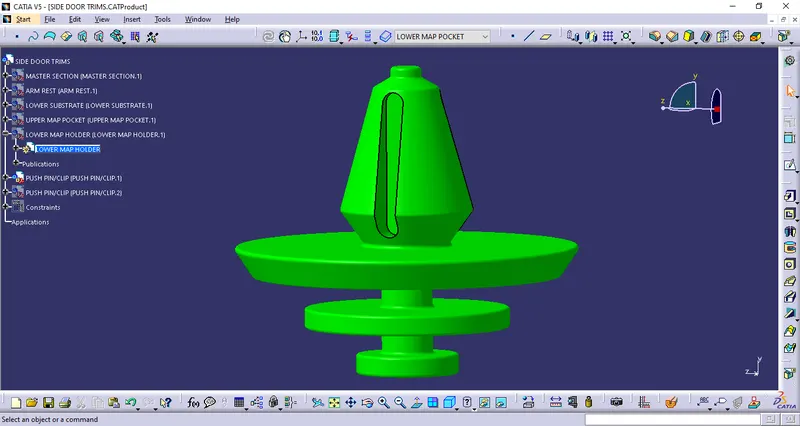
5.PUSH PIN
Push pin which heilp us locating and arresting component of an assembly and it provide alignment in mating parts and also act as various guide of mechanism. They are bascially attached to the dog house.
 Conclusion
Thus the Door Trim panel CAD model is created considering the design rules as like in OEM and tier1 companies.