Week 12- Final project
AIM:- To create a CAD model for door trim panel's parts by considering the given inputs of class A surface along with master section by following the design rules followed in OEM and tier1 companies.
Objectives:-
- To create individual tooling axis for the parts and perform draft analysis on the class A surface.
- To create the class B and class C surfaces from the given class A surface
- To form a solid geometry by combining all the surfaces
- To decide an attachment strategy for the part and create engineering features in reference from the master section provided.
- To perform draft analysis on the solid part model with all engineering features
- To assemble all the components together to obtain the final trim.
Given Data:-
Class A Surface for Door Trim Panel -
As we know in automotive industry there are complex products that we must design but this is not possible with simple sketches for that we need Class A Surface.
The A-surface or the styling surface is first checked for any gaps and other issues in its surfaces. This Surface acts as the input surface so any correction to be done should be with approval from the styling team or done by them. A- perfect surface is the one when a boundary is created, the lines are only on the edges of a component and its holes or cutouts as shown below.
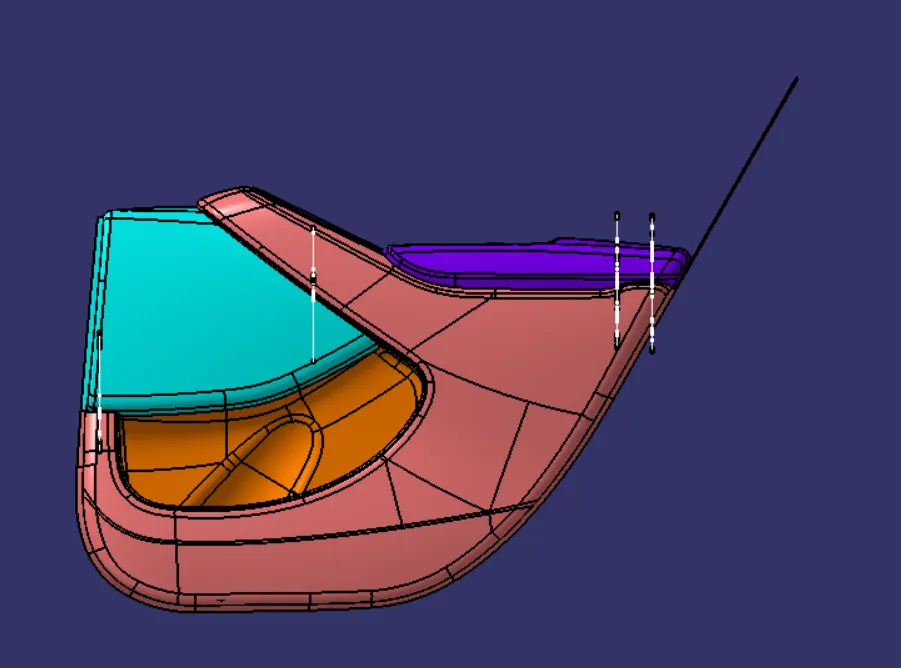
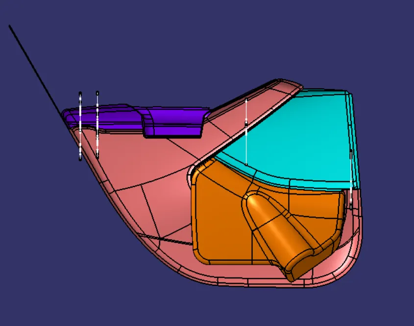
Steps Followed:
- The door trim panel is created by following steps -
- To check given Class A surfaces for any modification.
- To segregate given surfaces into separate part body namely Lower Substrate, Arm Rest, Map Pocket , Bottle Holder.
- To work individually on each part.
- To create tooling axis for part.
- Draft analysis on class A surface.
- Creation of class B and Class C surface.
- Create closed body from Class A, B and Class C surface.
- Followed same procedure to create all parts.
- Then create attachment features for all parts.
- Then do Draft analysis on final parts and then constrain them for assembly.
ARM REST
Class A Surface
A. Check Given Class A Surface for improvement.
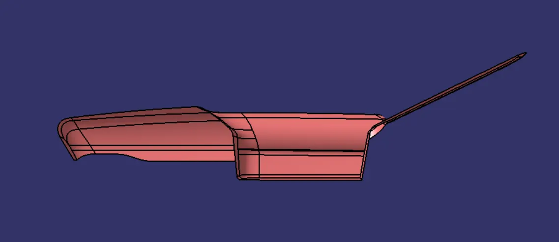
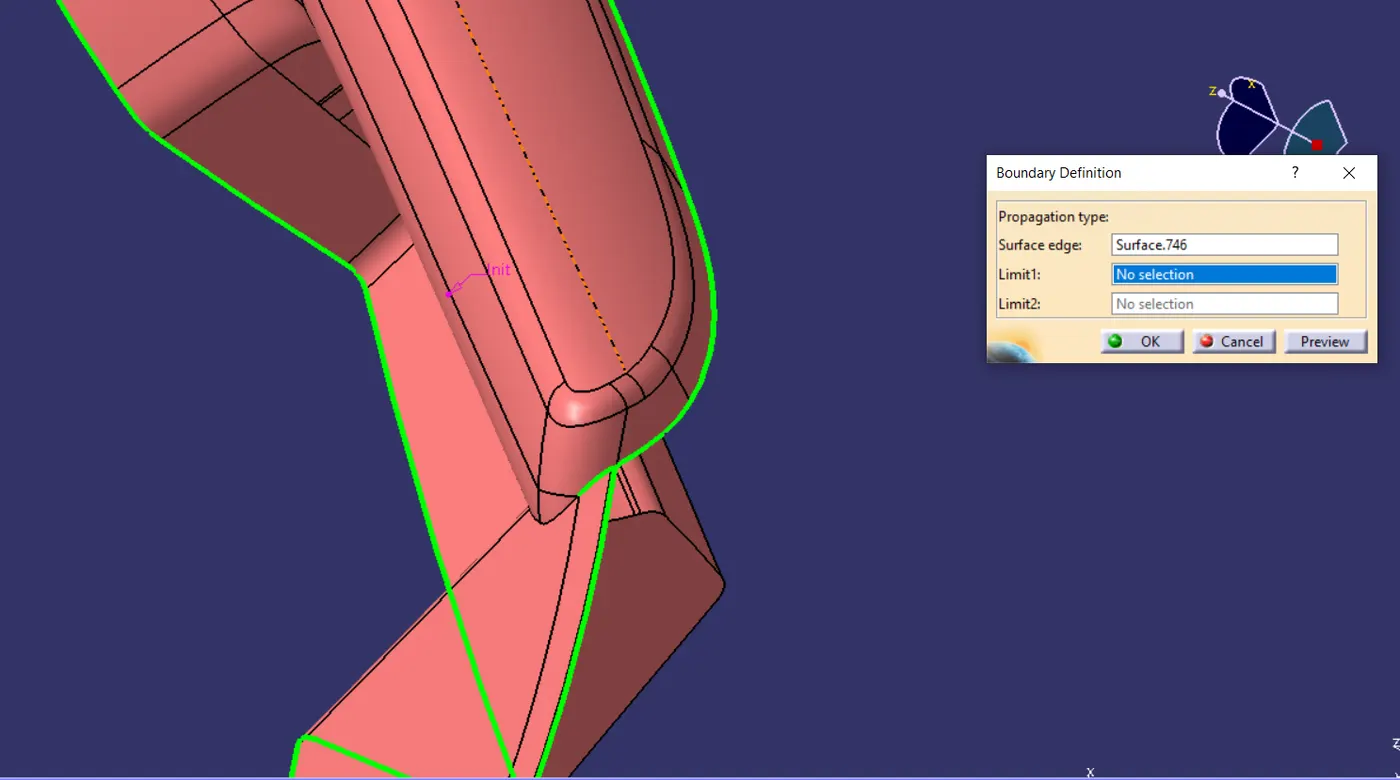
Given class A surface is not as good as needed . we must informed styling team for improvement.
B. Improvement of Class A Surface
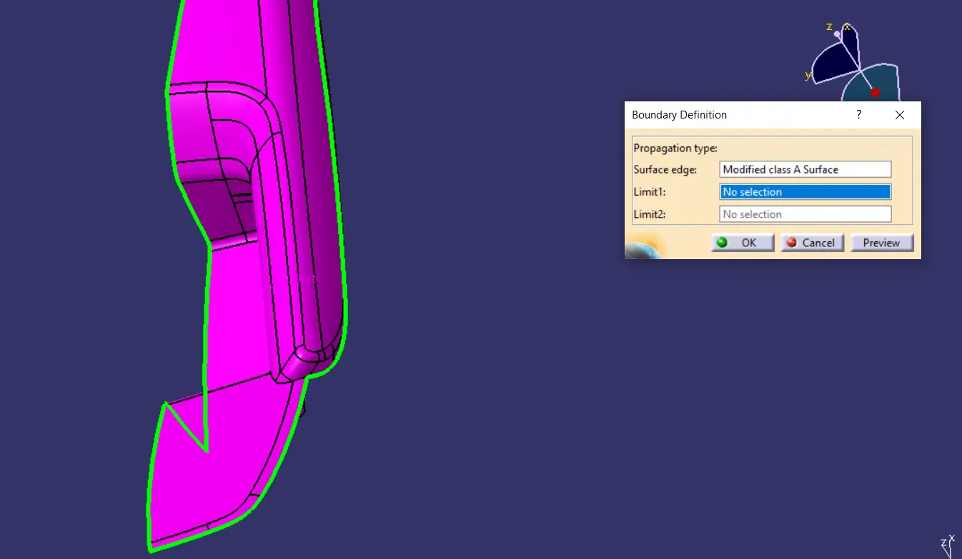
As shown in above image I have improved given class A surface in Surface workbench by using Surface operation such as extract, extrapolation, trim etc.
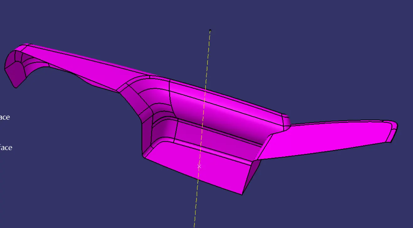
Creation of Tooling Axis - For molding of Arm Rest we need two tooling axis. Some area gets cleared with first tooling axis and remaining with second one.
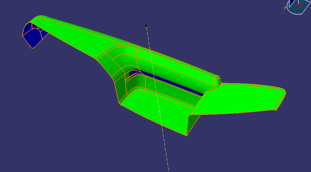
Draft Analysis of Class A
From above draft analysis we noticed that there is lot of space for improvement of class A Surface. We must request styling team for class A modification.
Creation of Class B Surface
Class B surface is created by offsetting class A Surface by 2mm as per the master section. After offsetting some area does not get offered, there patches formed. These patches are closed by surface creation features such as fill, multisession, blend etc.
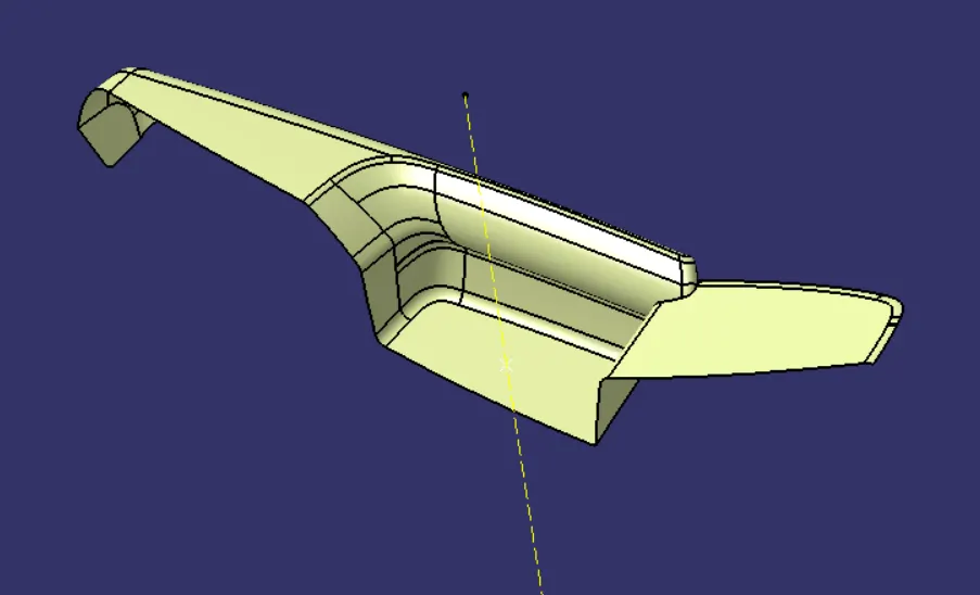
Solid Body of Arm Rest
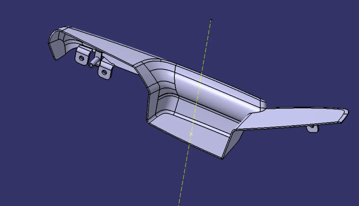
Creation of Flanges on Arm Rest
From master section we get the idea of flanges. I have created flanges on Arm Rest by considering counterpart (Lower Substrate) position.
Draft Analysis on Solid Body of Arm Rest
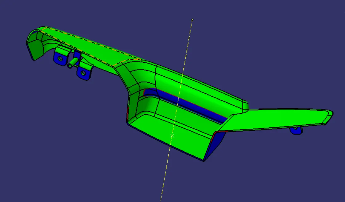
DRAFT: The draft is something that allows the component to release or eject from the mold properly. The draft is required on all parts in the direction of mold movement to allow parts to release properly. Most parts or applications require a minimum of 1/2 to 1 degree; however, 3 degrees is widely accepted as the norm.
- The draft is given in the direction of tooling direction or core cavity opening.
- If we don't give the draft to the component it sticks to the mold and friction also act so we get the damage in our part so to overcome this, we give some draft angle to overcome this problem.
- As mentioned above we have two tooling axis for Arm rest.
- Following images give the idea about is it manufacturable or not.
- From above draft analysis we notice that given part is not as good to manufacture. There is lot of modification needed. We must request styling team to improvement in class A at particular areas.
MAP POCKET
Class A Surface
Check Given Class A Surface for improvement.
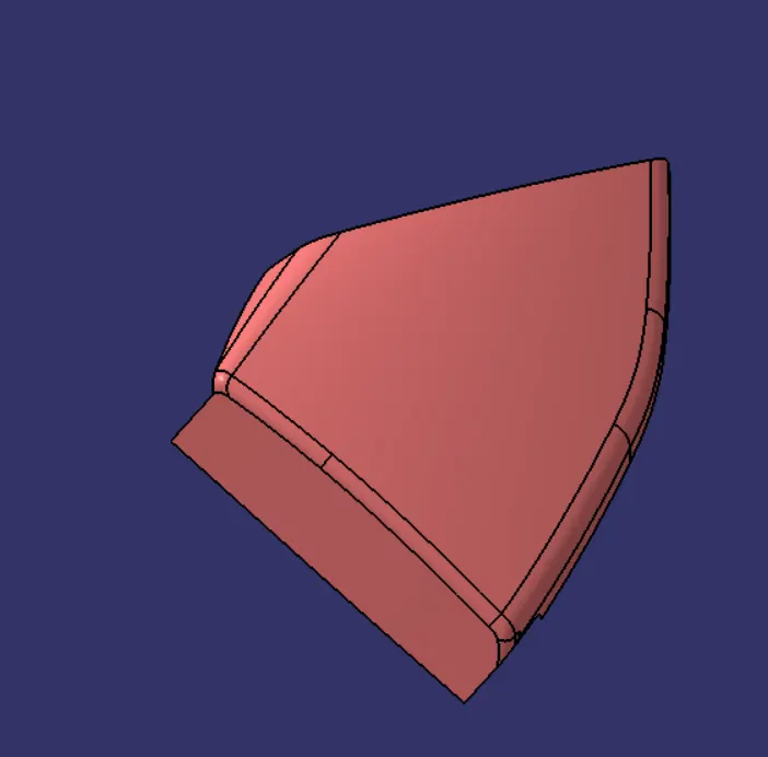
Creation of Tooling Axis
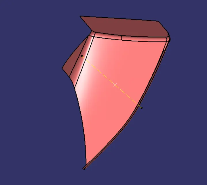
Draft Analysis on Class A
From above draft analysis we noticed that all Surface have minimum 3-degree draft.
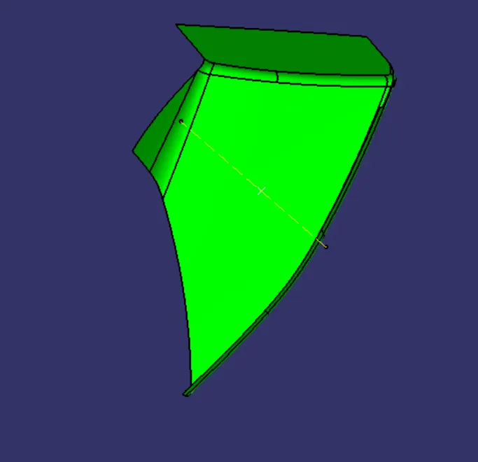
Creation of Class B
Class B surface is created by offsetting class A Surface by 2mm as per the master section. After offsetting some area does not get offered, there patches formed. These patches are closed by surface creation features such as fill, multisession, blend etc.
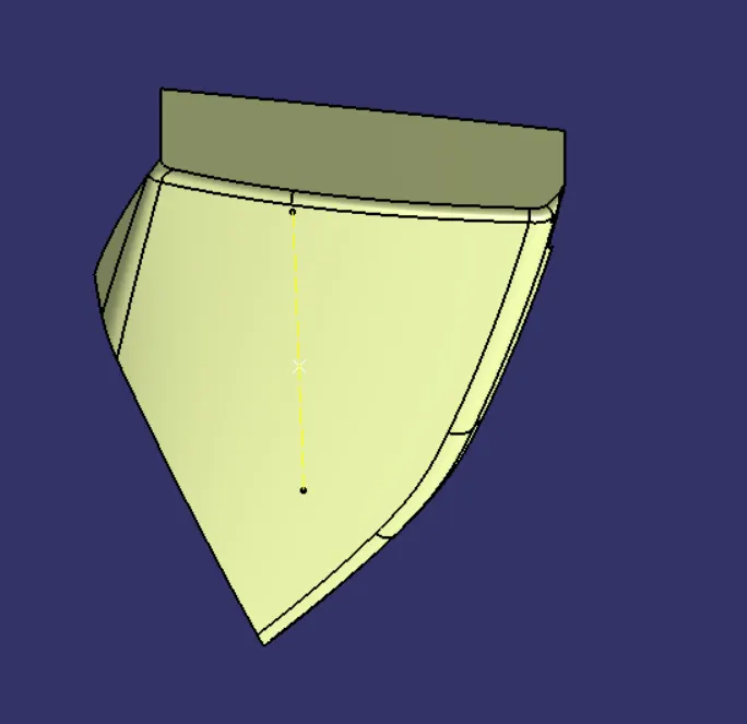
Final Solid Body of Map Pocket
Creation of Flanges
From master section we get the idea of flanges. I have created flanges on Arm Rest by considering counterpart (Lower Substrate) position.
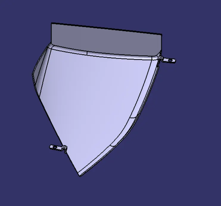
Draft Analysis on Final Body
From above draft analysis we say that map pocket is manufacturable. All Area have minimum Draft of 3 degree.

BOTTLE HOLDER
Class A Surface
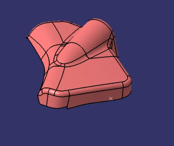
Creation of Tooling Axis
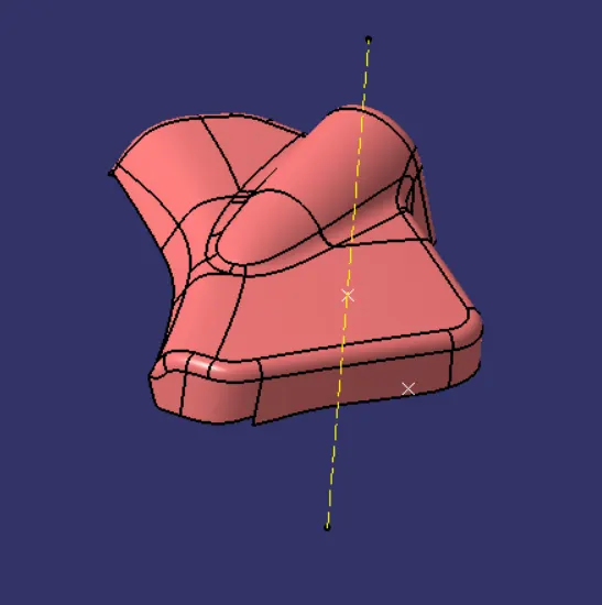
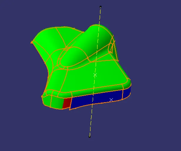
Draft Analysis on Class A
From above draft analysis we notice that some areas are not have minimum 3-degree draft. Blue color area shows negative draft for that we must informed styling team for improvement in class A.
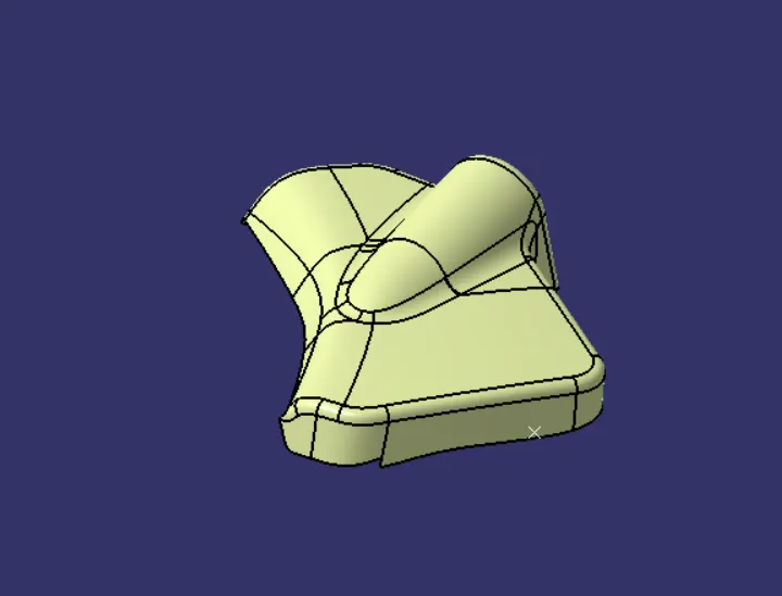
Creation of Class B
For creating Class B surface, we must offset it by 2 mm as shown in above image.
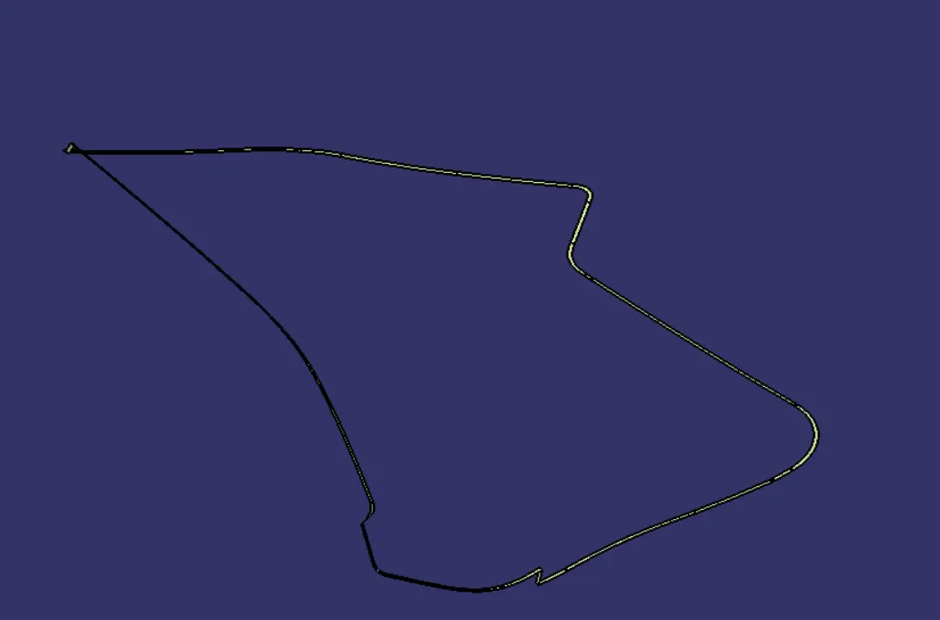
Creation of Class C
For creating class C surface, we must use sweep feature of surface creation.
Solid Body of Bottle holder
Creation of Flanges
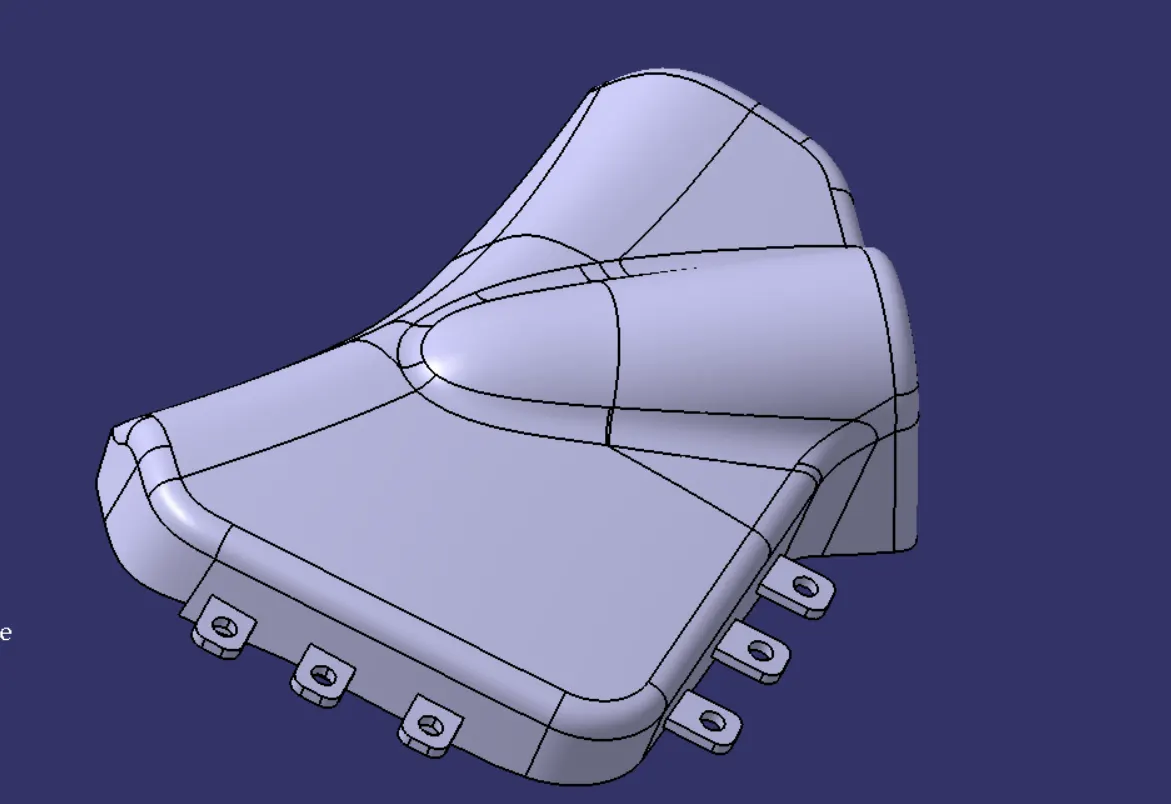
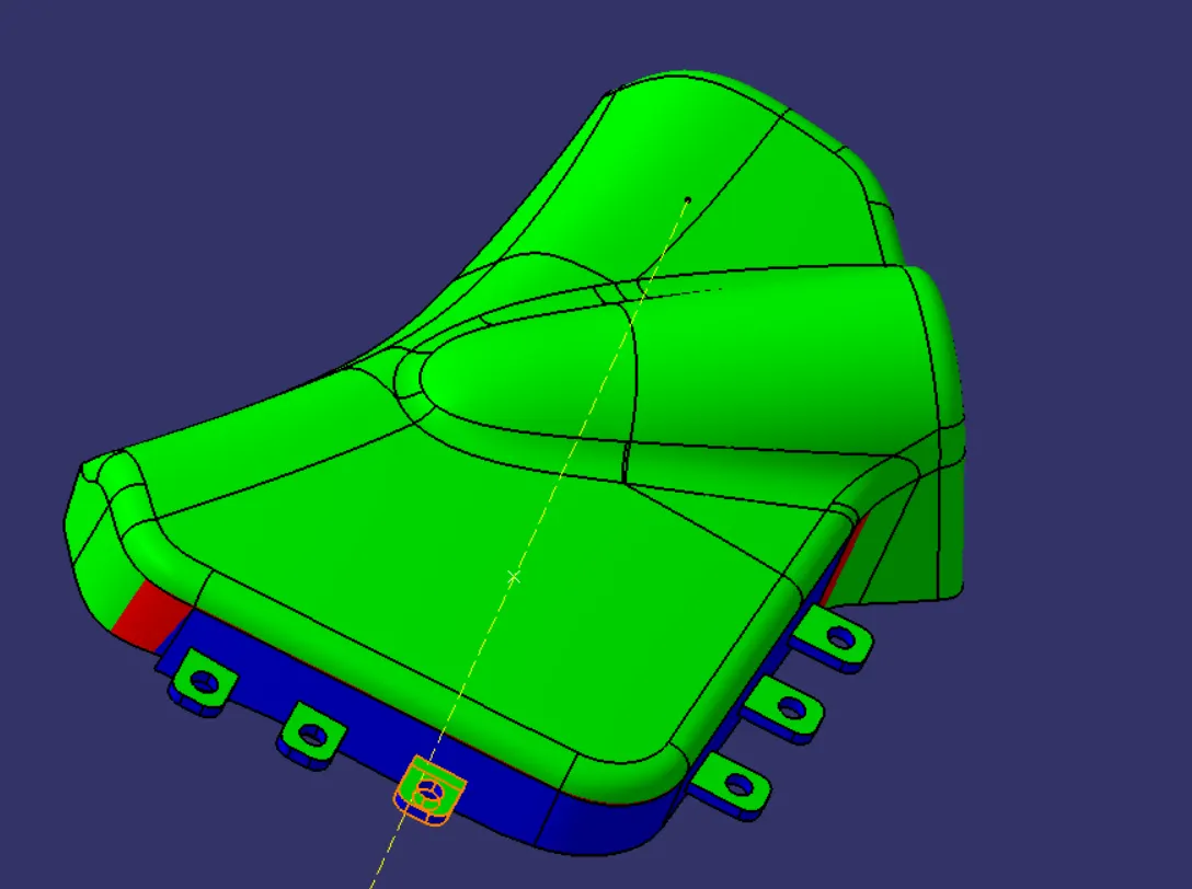
Draft Analysis on Solid Body of Bottle Holder
From above draft analysis we noticed that bottle holder part is not as per requirement. It is not manufacturable because at some area it has negative draft for that we must informed styling team.
LOWER SUBSTRATE
Class A Surface
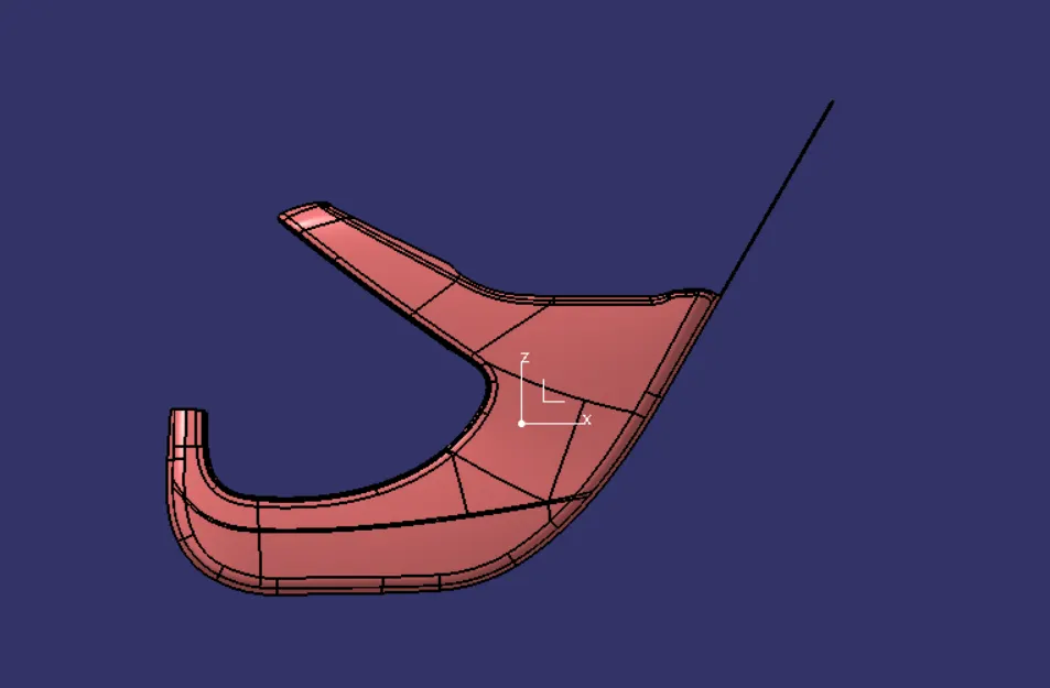
Creation of Tooling Axis
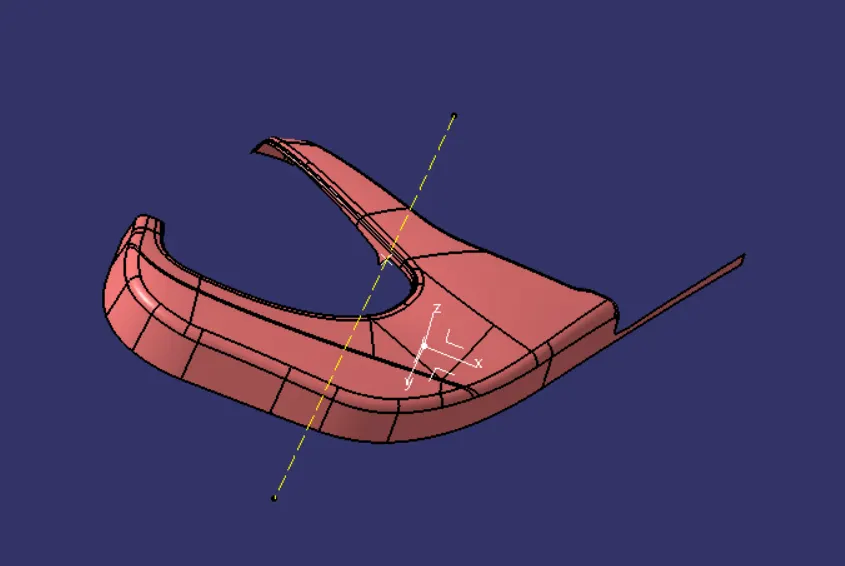
Draft Analysis on Class A
From above draft analysis we say that given class A is of good quality. All area has minimum 3 degree of draft.
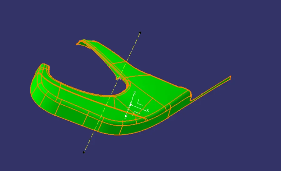
Creation of Class B
Class B created by offsetting class A by 2 mm.
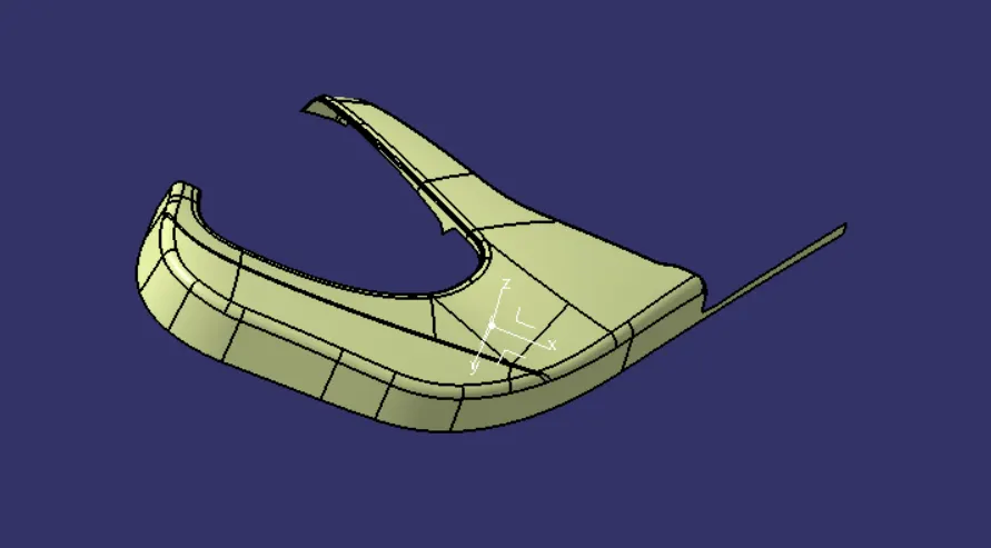
Creation of Class C
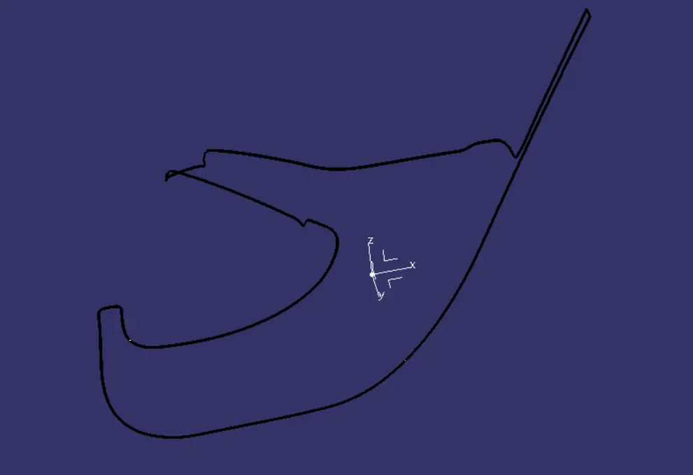
Creation of Solid Body
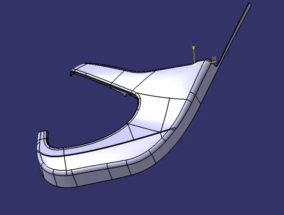
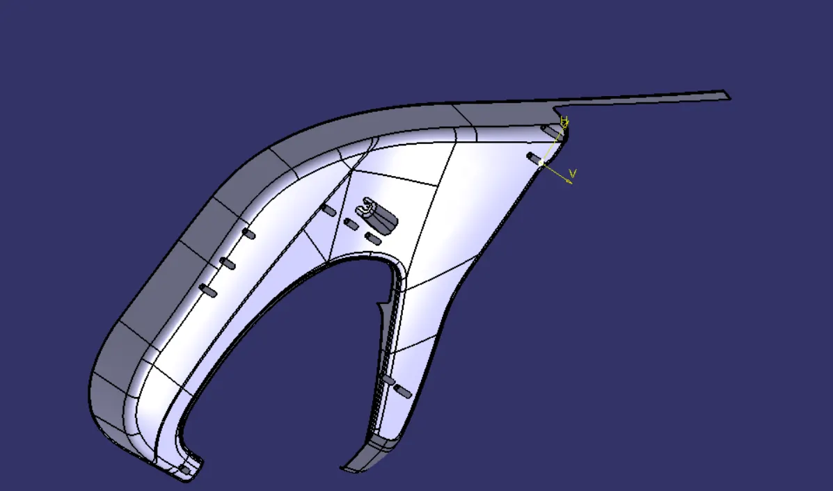
Draft Analysis on Solid Body
From above draft analysis we noticed that all the area has minimum 3 degree of draft.
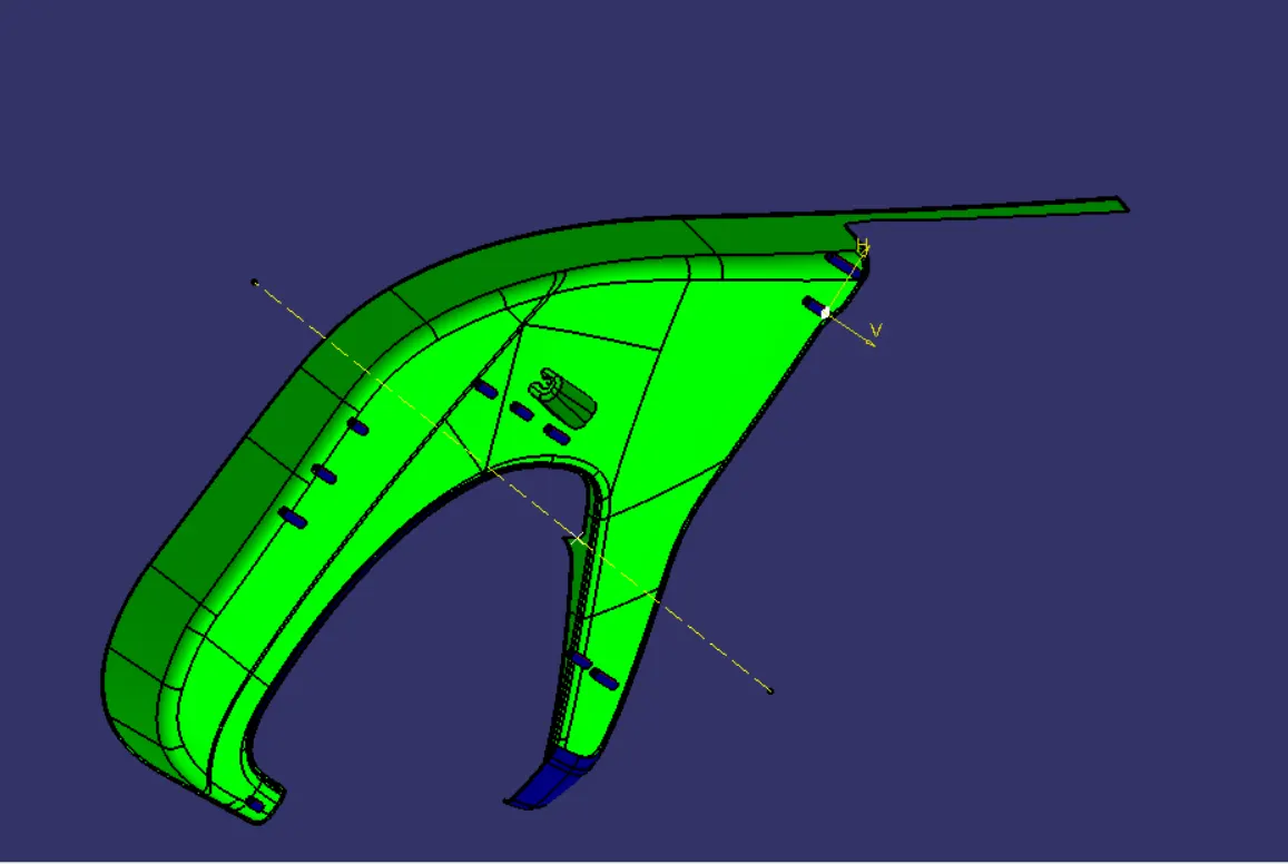
Creation of Heat stake
HEAT STAKES
Heat stakes are used in thermoplastics to assemble two parts together by locally heating and cooling the plastic material and allowing it to reform itself and act as a joint for the two materials.
We have placed 9 heat stakes in the model based on the reference points created by estimation.
One of the important factors to be considered while designing the heat skates is the height of the heat skates. It should always be less than the height of the locators.
Draft Analysis on Heat Stake
Creation of Locators
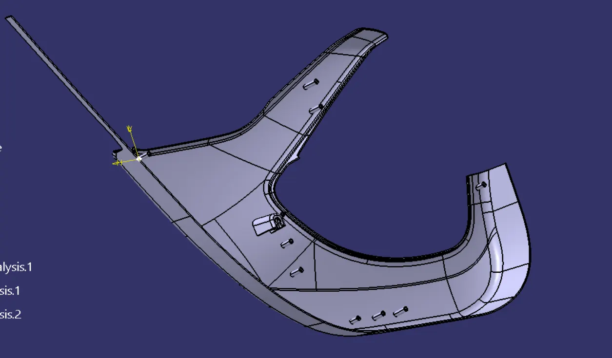
LOCATORS
- The main purpose of locators is to facilitate proper locking of two components together while assembling and arrest the maximum degrees of freedom possible.
- These locators are like guide pins provided in mold.
- The two types of locators used are two-way locator and four-way locator.
- We have positioned three 4-way locators in our model which meet the rib design criteria.
Creation of Doghouse
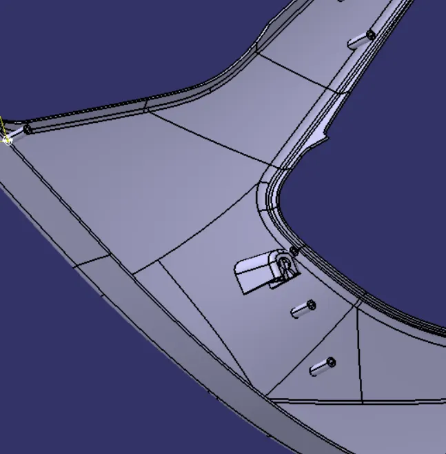
DOGHOUSE
- The two main purposes of a doghouse are to avoid sink marks and to house various other engineering features like screw boss, locators, push clips etc.
- In this case, the doghouse is designed to house the push clips and the 4-way locator. The doghouse designed for the push clip features a slot on the top face to accommodate the push clip.
- The doghouse should follow certain design rules which are stated below.
- Doghouse wall thickness at the intersection of the part wall (C) should be 40% or less than the main wall stock (T).The height of (B) should be between 3.0 – 6.0 mm.
- Outer surface of doghouse must have a draft angle of 3 degrees.
- Inner surface of doghouse must have a draft angle of 0.5 degrees.
Final Assembly
- For final assembly of door trim panel, we must contain all parts together.
- Following image shows the assembly of push pin with doghouse.
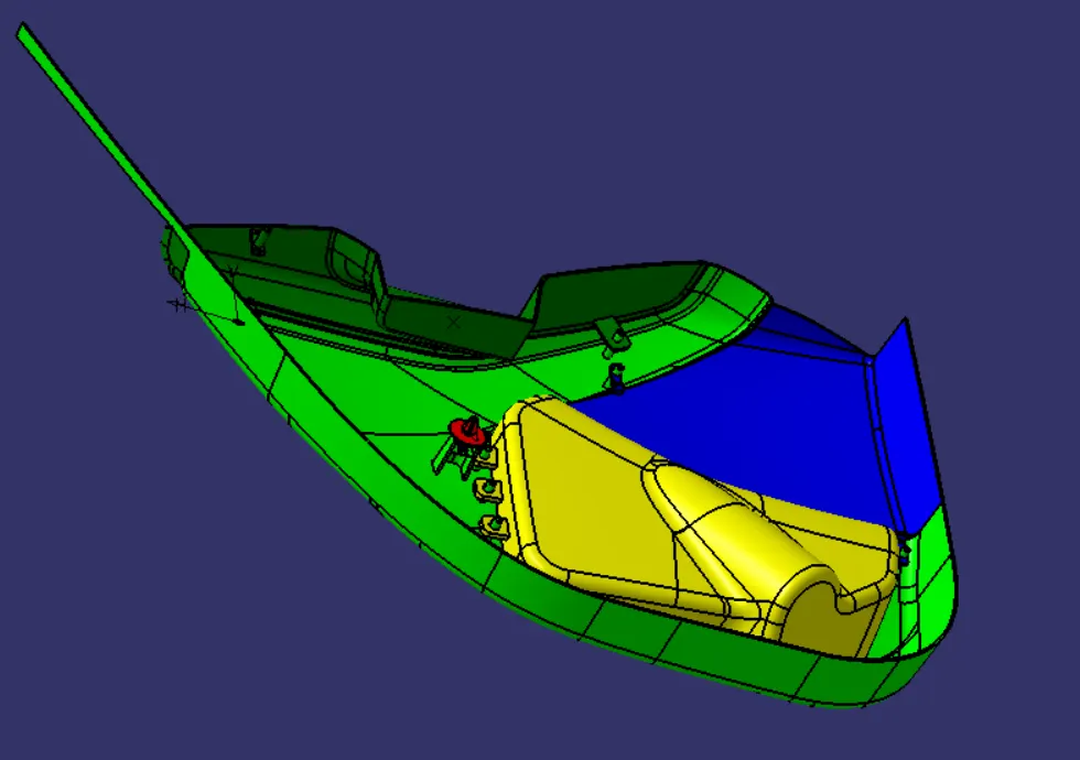
- In the same way we must constrain all the parts together.
- Following tree structure shows the how all part is constrained.
CONCLUSION
From this project learned how to create CAD model for plastics parts by considering design rule. By doing this project on Catia V5, very well familiar with part workbench, surface workbench, Assembly workbench.