Week 12- Final project
Aim
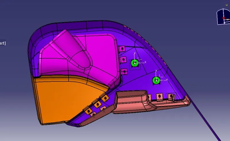
To design the lower door trim from the given input, along with the engineering features to assemble the product whenever needed.
Requirements to achieve our objectives.
- Create thickened part using the master section for reference
- Create the mounting features as per design guidelines in the industry and with master sections
Door trim Lower
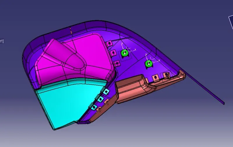
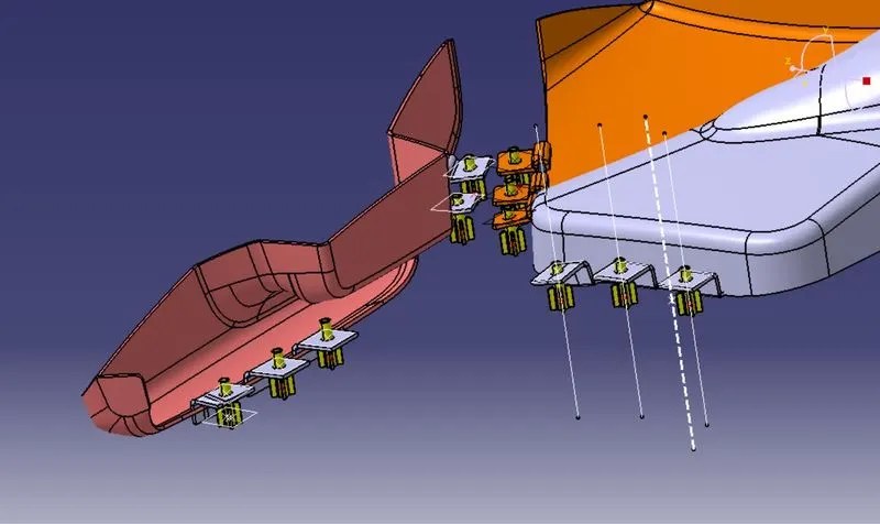
It is an assembly of many components that join together, and it serves the purpose of aesthetics and provides a seat for some of the controls.
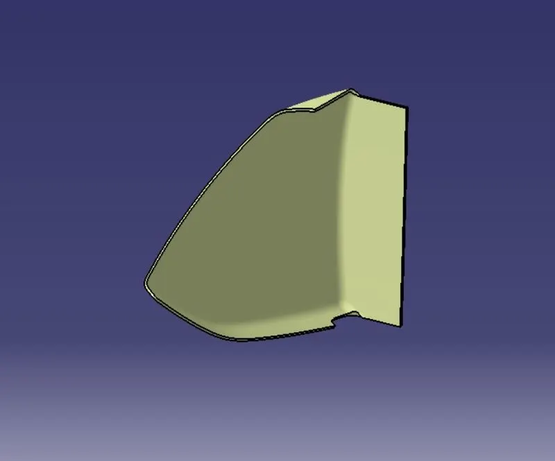
Here are assembly contains the following parts0
- Lower Substrate
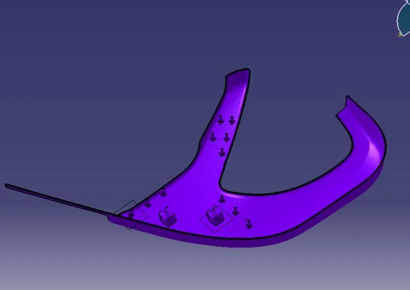
- Bottle Holder
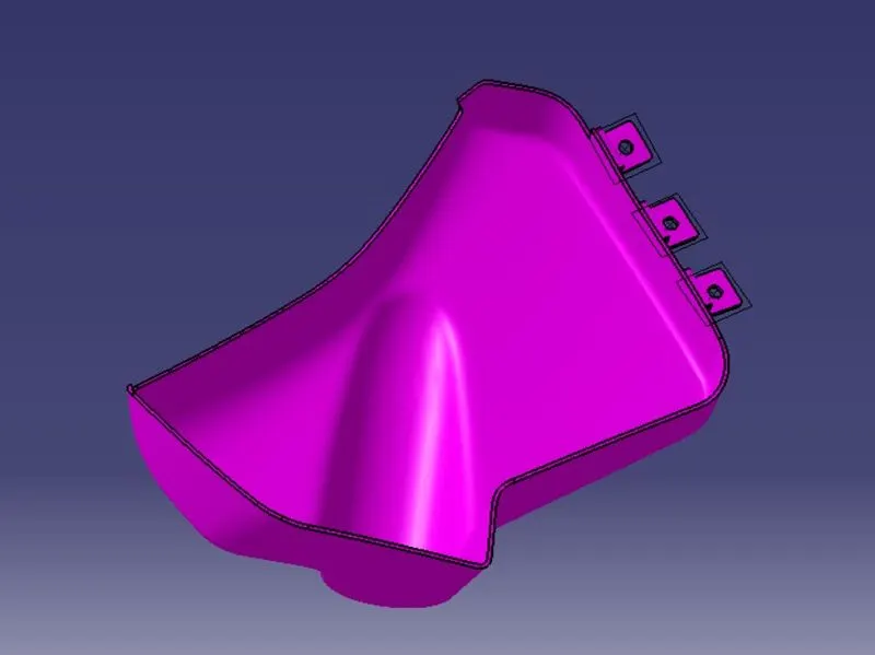
- ARM Rest
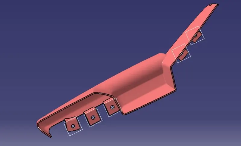
- M Pocket
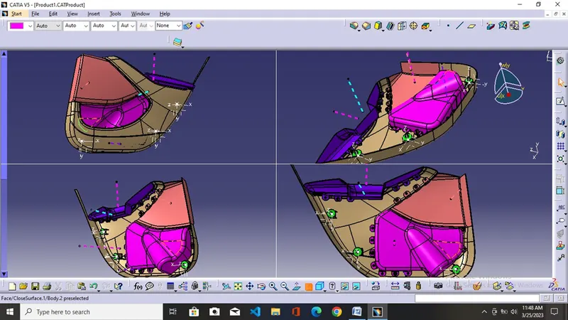
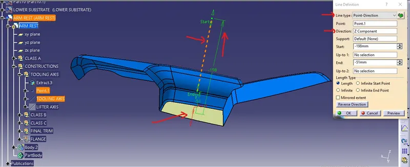
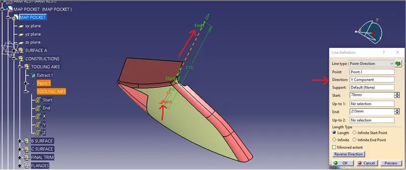
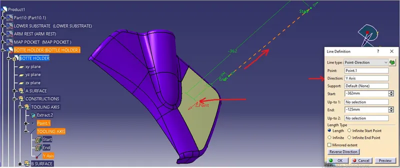
TOOLING AXIS
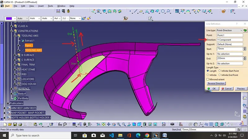
It is the direction along which the mold opens for easy ejection of the solid part.
Number of processes To Creating Tooling AXIS
- By making tooling axis along the X, Y, and Z axis
- By making the tooling axis normal to the part surface
- By using the bisection method
- Creation of the required tooling axis using the line tooland selecting the point and direction option to give extracted surface in the reference surface option and the previously created point in the reference point option and obtain the required tooling axis.
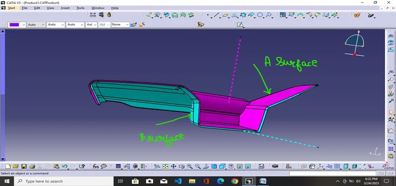
B Surface
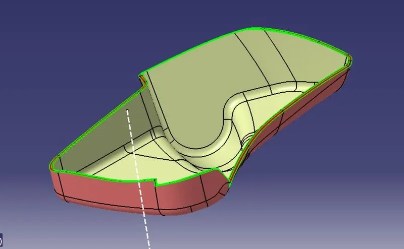
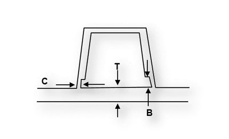
It is the surface that is offset from the class A surface to distance to the measured thickness and it also serves as the surface which seats the engineering side feature. It is a surface that is not visible to the user
C surface
It is the joining surface that serves as a bridge between the class A surface and the class B surface thickness of this depends upon the thickness of the product
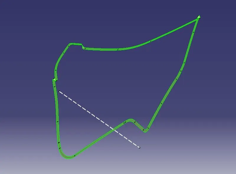
- Bottle Holder
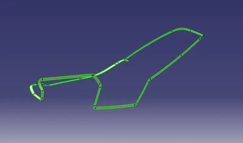
- ARM Rest
- M-Pocket
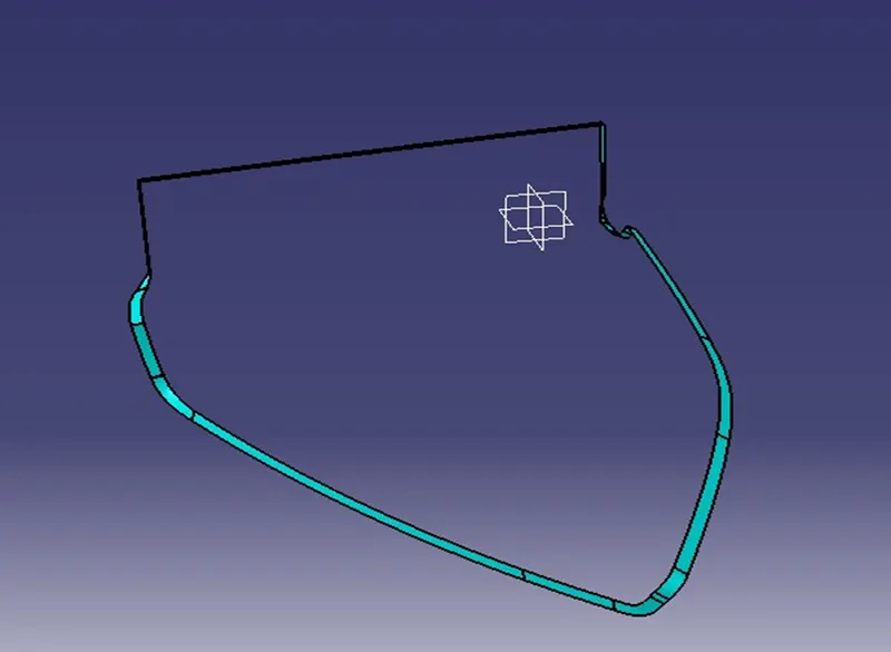
- Lower Substrate
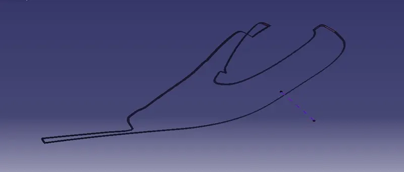
SOLID BODY
After the formation of the B and the C surface, we finally trim or joined them with the A surface to form the required closed surface after that, we can use the close surface tool in the part workbench to make the plastic component into the solid one.
- ARM Rest
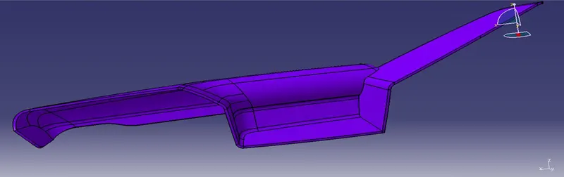
- M-Pocket
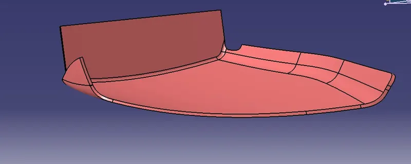
- Lower Substrate
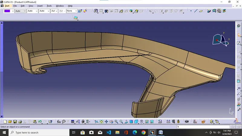
- Bottle Holder
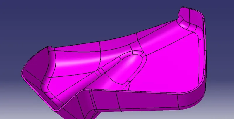
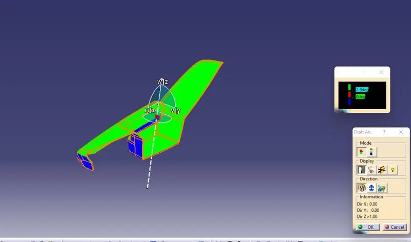
Draft analysis
It gives us information about the parts which tells us which part clears the mold walls easily so as to minimize the machining process in the finished product and final product ejected easily and minimize the contact between the product and mold walls.
- Select the Feature draft analysis tool and move the compass to the tooling direction and align the compass w axis to the tooling axis. After aligning the compass with the tooling direction again click the compass tool to insure the proper alignment of the w-axis with the tooling axis. After the proper alignment uses the locking tool to lock the compass with the tooling axis.
- Click anywhere on the A surface to generate the draft analysis report and use the quick analysis mode option to see the color code values where the green color defines the parts which have a draft angle greater than the green color code value generally it is up to 3 degrees in values. The red color gives information about the parts which have angles between 0 to up to a green color value which is generally up to degrees. The blue color gives information about parts that have an angle less than the red color. If A surface comes out in green color means our tooling axis is perfect and we are ready to go for the formation of B and C surfaces.
- Lowe Substrane
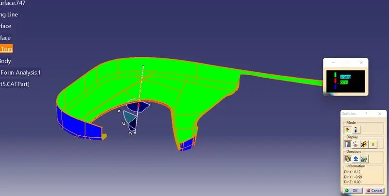
- Bottle Holder
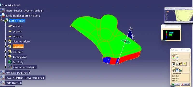
- M-Pocket
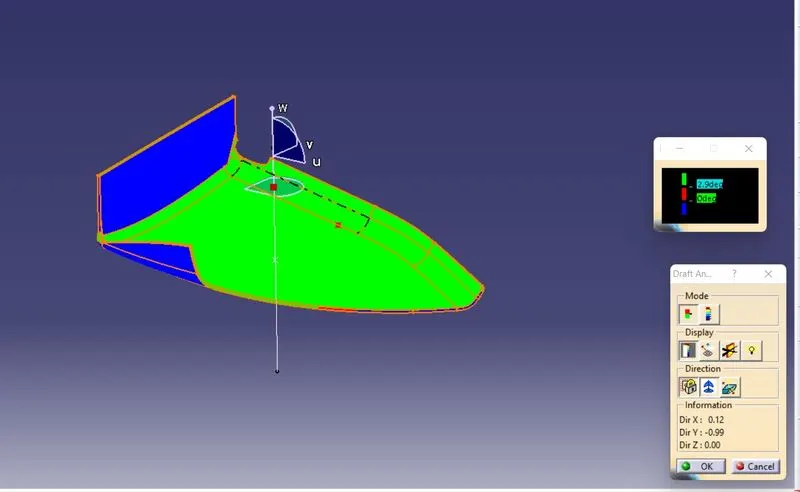
- ARM Rest
Here we see that some ( Blue )surfaces of the Arm Rest do not clear we can inform the class A designer to improve the A surface which serves as our input.
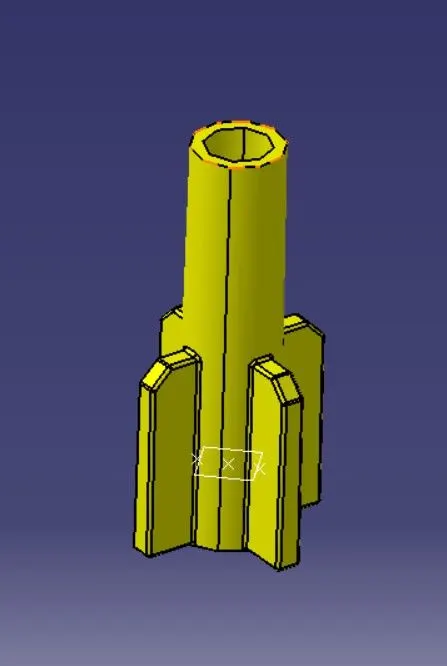
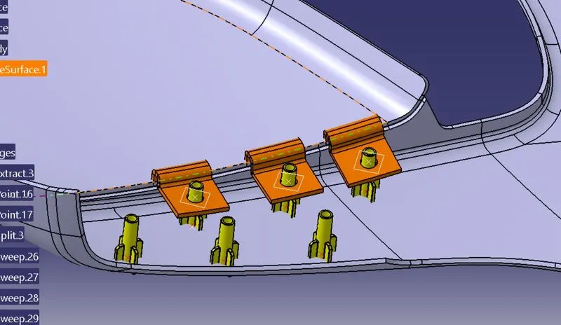
Heat Stake
It is a component used for joining the two different components using a process of heating and cooling the temperature of plastic components known as heat staking.
Rules for making heat stake
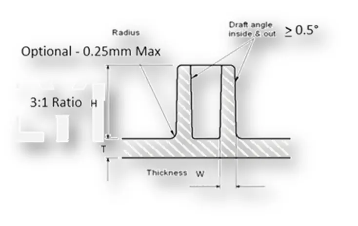
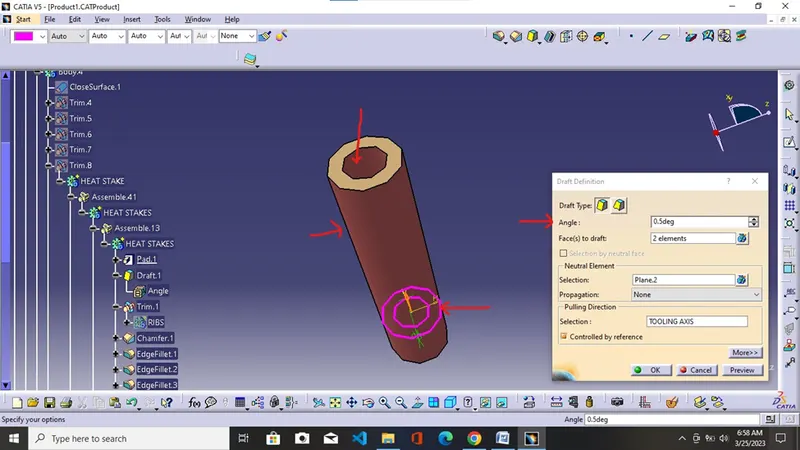
While giving the draft angle as 0.5 degrees to the outer and inner surface of the heat stake so that it makes it clear with the draft analysis. While giving the distance between the two heats stakes around 50mm along the curve.
Dog House
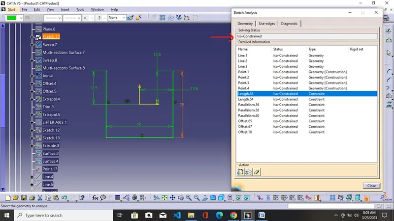
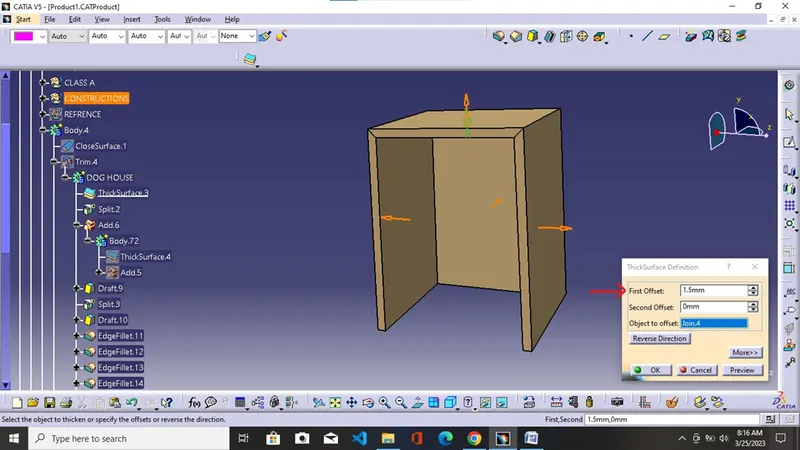
This engineering feature is used for the seating of other engineering features and provides height without making sink marks and other plastic defects on the A surface.
Lifter Axis
This is the axis used for the draft analysis while clearing the inner surface of the dog house. Providing 0.5 degrees to the inner surface will achieve the desired degrees for the proper ejection of the core and cavity without distorting the inner surface.
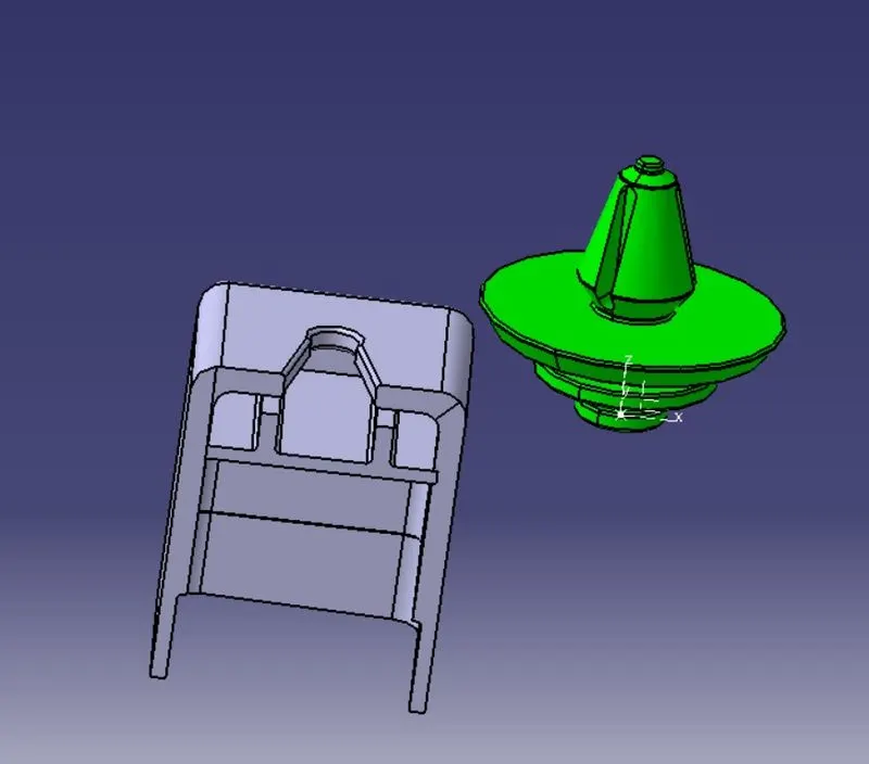
While arranging the Dog house always tries to keep the gap between the front face in the direction of the lifter axis is 90mm for the easy removal of the core while traveling in the direction of the lifter axis.
Push Pin
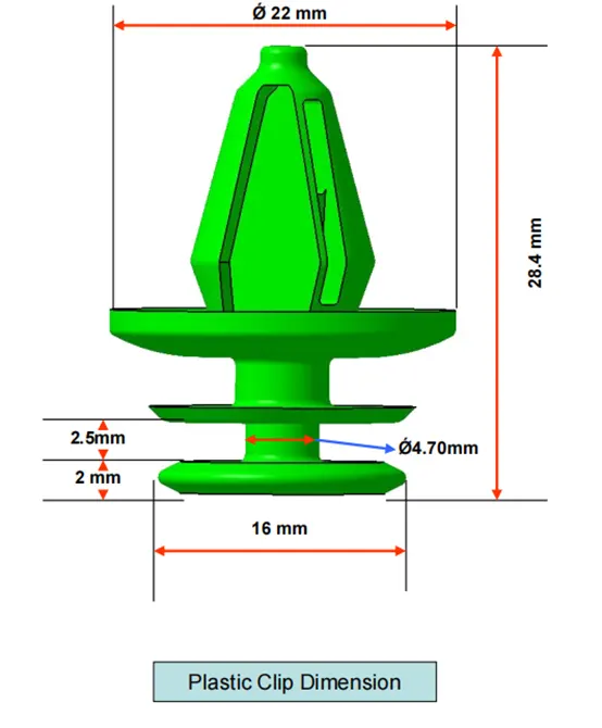
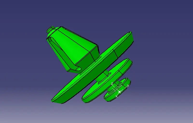
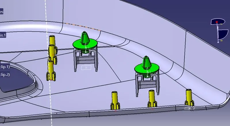
Push pins are a popular mechanical attachment because they provide flexibility and dependability at a low cost. Flexible design. Hole location and attachment forces can be customized for each specific application.
Attachment Features
- Heat Stackes
- Dog House
- Lifter Axis
- Ribs
- Flanges
FINAL PRODUCT