Week 12- Final project
FINAL PROJECT
AIM: To develop the Door Trim panel.
OBJECTIVE:
Creation of CAD model considering following inputs as like in OEM and tier1 companies.
a) Class A surface
b) Nominal thickness : Refer master sections
c) Attachment strategy :
- Find a attachment strategy for the door panel complete work.
- Use Push pin with Dog house for Lower substrate – Door panel attachment
- Use heat stakes for part to part attachment
OUTPUT REQUIRED:
- Create thickened part using master section for reference
- Create the mounting features as per design guidelines in the industry and with master sections
- Apply material details :
- Draft analysis & Tooling analysis
- Creation of parting lines and check tooling feasibility.
INPUT:
CAD DATA is downloaded and Opened with CATIA.
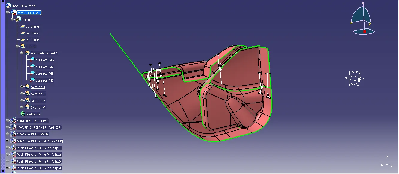
Given CLASS-A surface.
Design Methodology:
Class-A surface means visible surface. It gives the aesthetic of the component which is created by the styling team and gives to the part design engineer to create the part with all engineering aspects.
Procedure for Tooling axis creation:
- Check the best possible tooling direction by manually adjusting the compass.
- By analysing it is found that y axis as tooling direction would clear most of the faces without any difficulties.
- Now extract any surface and create a mid-point on it.
- Then create a dummy axis creating a line on the point and direction along the y-axis.
- Perform draft analysis to find whether the given axis clears the draft analysis. If not create a new tooling axis.
- Draft analysis of CLASS-A surface.
DRAFT ANALYSIS:
- Draft is done on the Class A surface of the parts
- Change it to material in customize view.
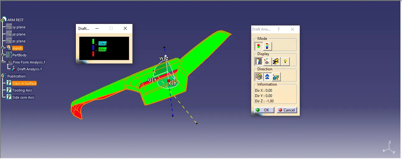
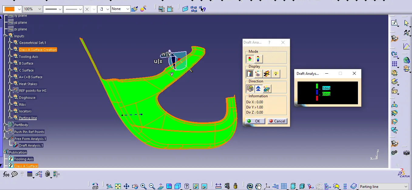
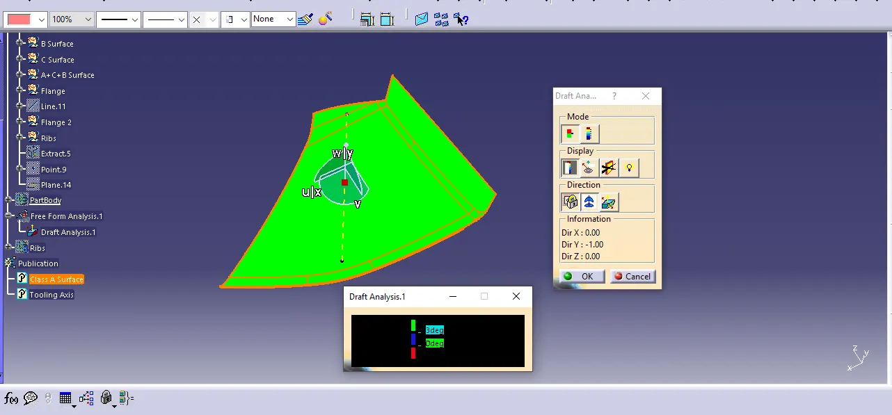
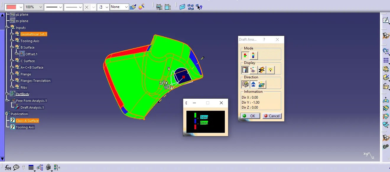
- Click the Draft analysis tool and click the surface and align the compass to tooling axis.
- 3 degree is the clearing angle
- So here is photo of cleared (Green) draft.
ARM REST:-
Creation of Tooling Axis and Draft Analysis.
LOWER SUBSTRATE:-
MAP POCKET UPPER :-
MAP POCKET LOWER:-
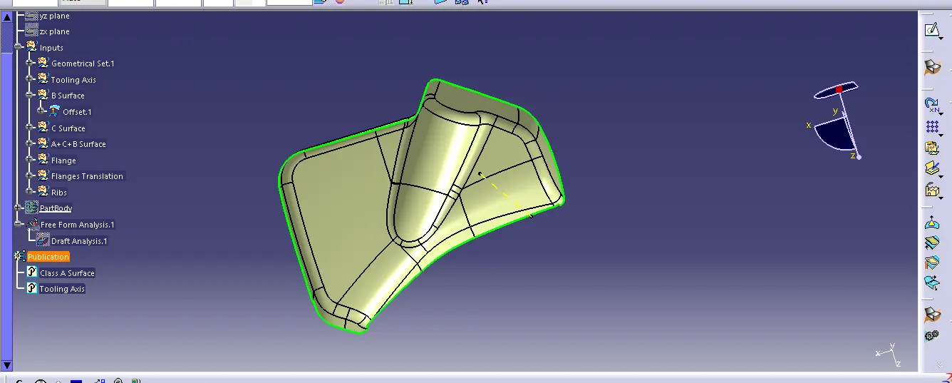
CLASS-B surface creation:
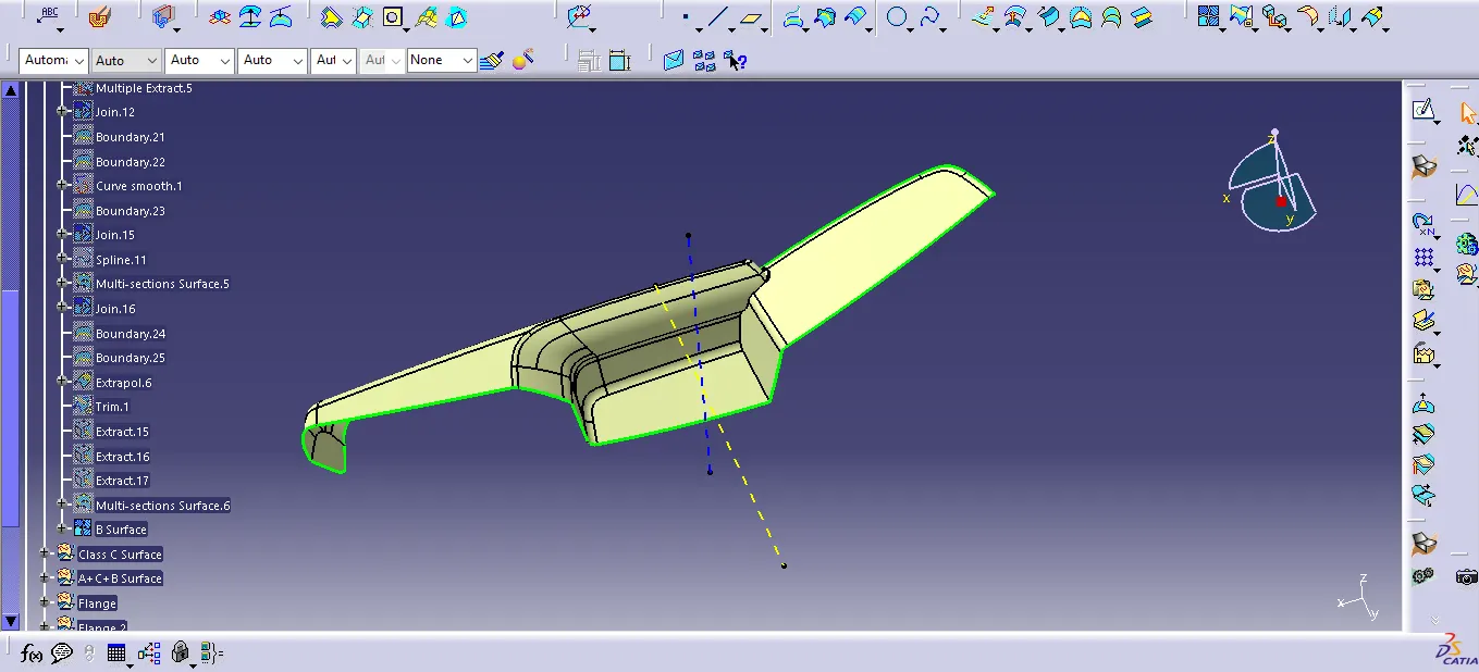
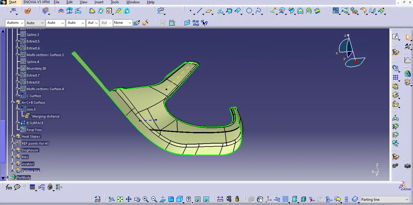
Class-B surface means the thickness of a part it is not visible and is inside part. In other words, the Class-B surface is a surface below a certain thickness from the class-A surface. This is the surface that contains engineering aspects of a model.
- Create offset surface of CLASS-A about 2.5mm inward direction.
- Check for discontinuity and rework on the offset surface using extract, multi-extract, multi sections surfaces.
- Join the surfaces and ensure the final CLASS-B surface created has no gaps.
ARM REST:-
LOWER SUBSTRATE:-
MAP POCKET UPPER :-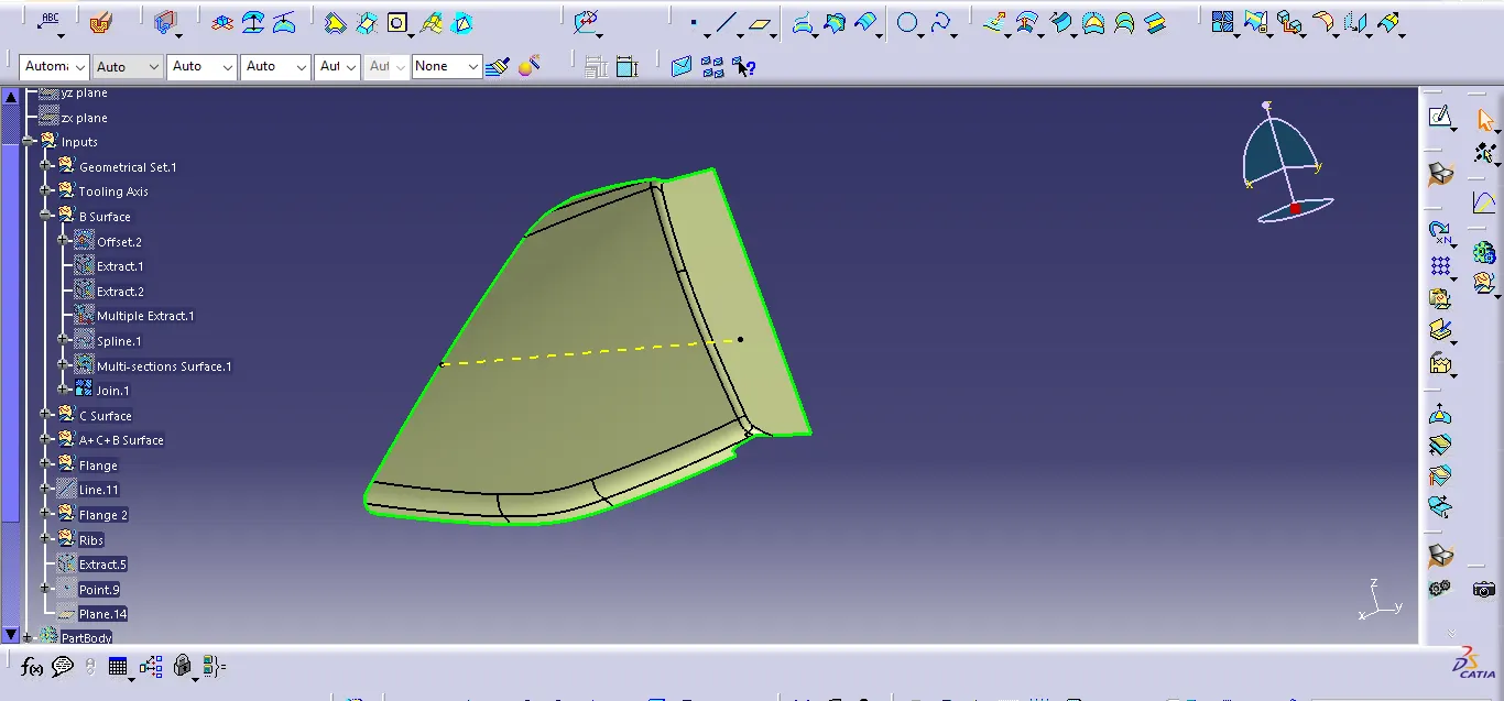 MAP POCKET LOWER:-
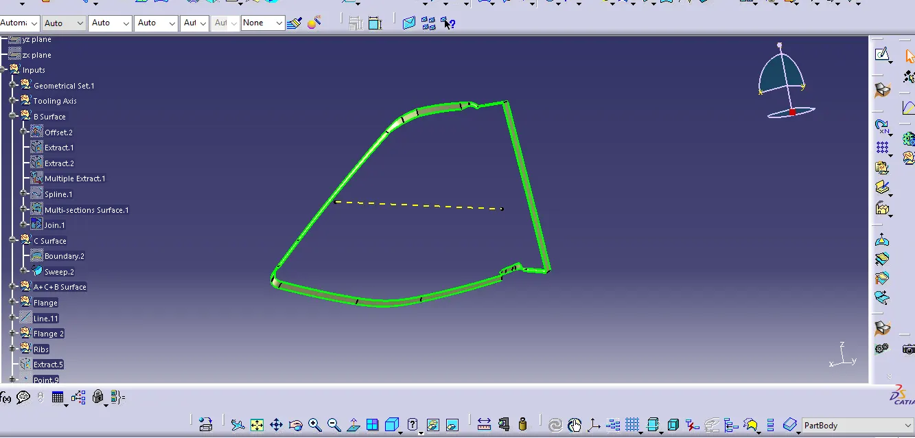
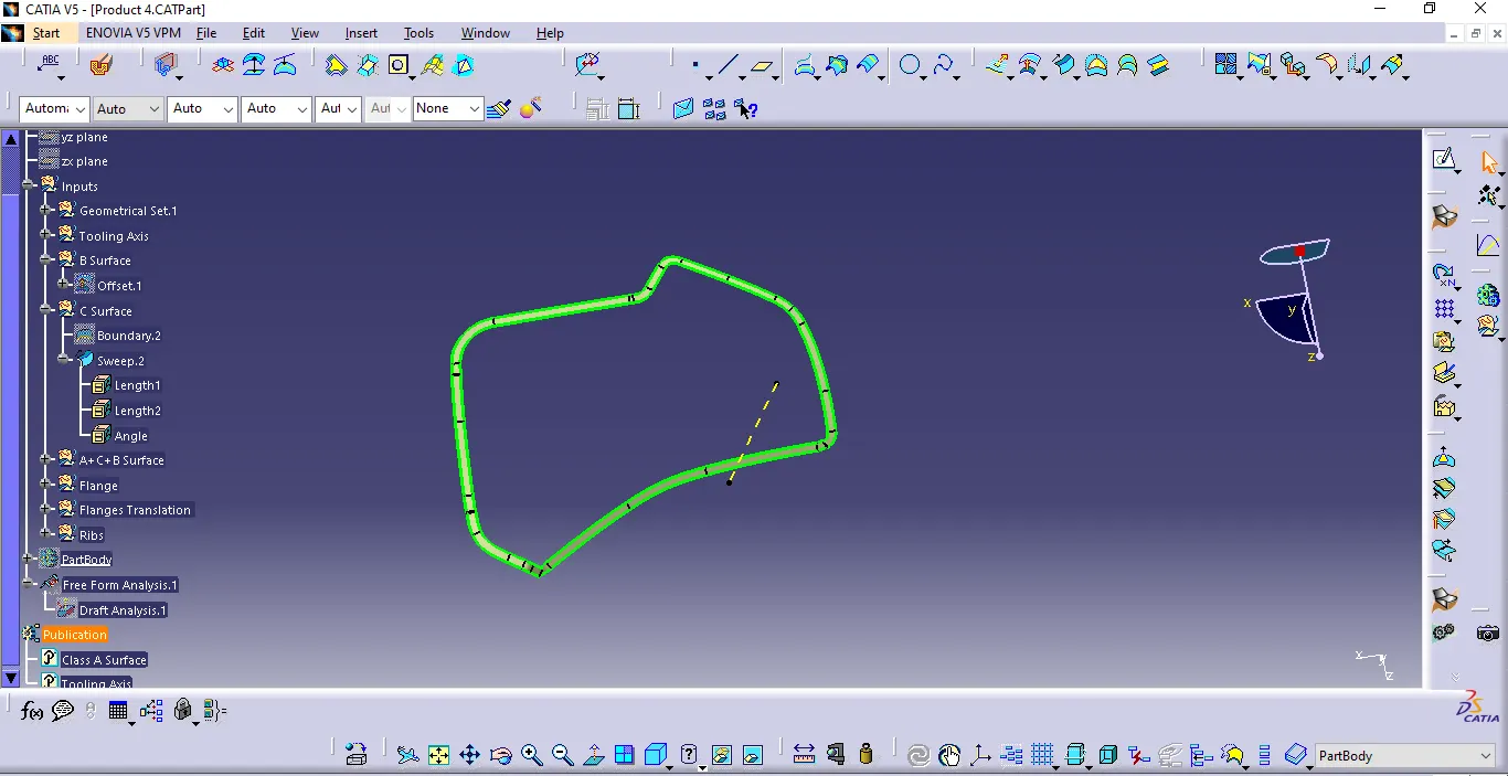
CLASS-C surface creation :
The surface that joins class-A and class-B surfare that is class-C surface. Class C is often specified for interior surfaces not readily visible, surfaces that will be covered by another part when assembled.
- Create the sweep concerningerence to the surface and tooling axismulti-extractingting the CLASS-A boundary.
- Join the sweep surfaces by using commands like extrapolate, multi-sectiontion surface.
- Finally join all the sweep surfaces and ensure the continuity of the CLASS-C surface.
ARM REST:-
LOWER SUBSTRATE:-
MAP POCKET UPPER :-
MAP POCKET LOWER:-
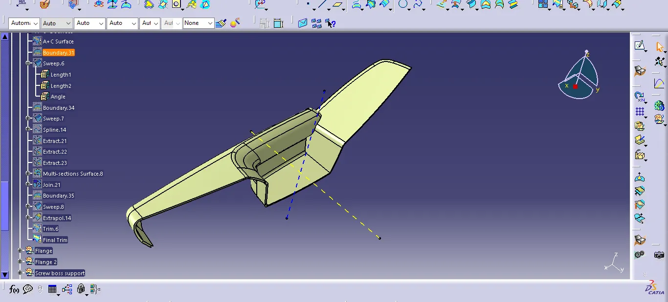
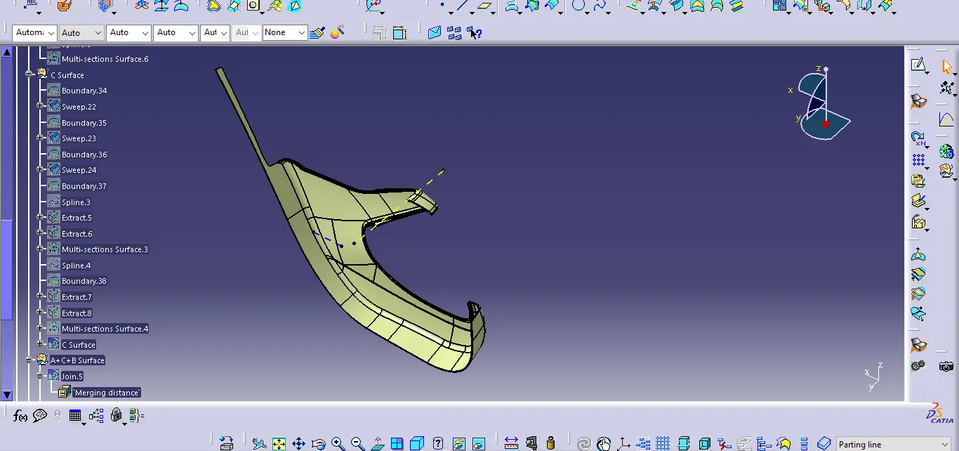
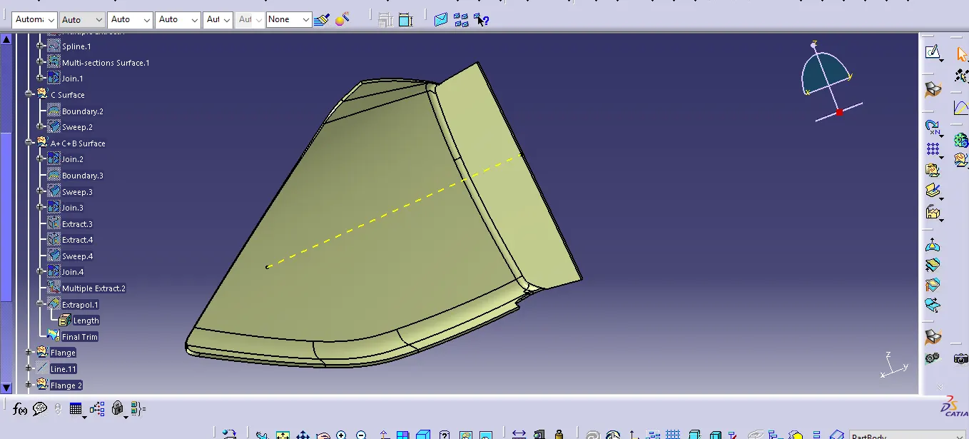
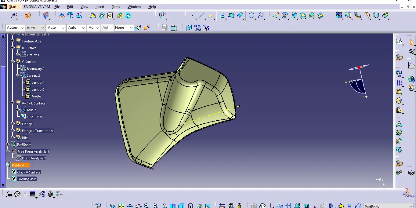
FINAL TRIM:
- Join A and C surface.
- Trim with the B surface.
ARM REST:-
 LOWER SUBSTRATE:-
 MAP POCKET UPPER :-
 MAP POCKET LOWER:-
 Master section is used to create the Sketches
- It is then extracted and pad in part design
- Thicken, split are also use the B Side features as per the Design Guidelines
Dog houses are made to prevent the SINK MARK that screw bosses leave on CLASS-A surfaces and to address the length problems that arise when attaching screw bosses to other components.
It is especially helpful when the part needs screw bosses that are perpendicular to the direction of tooling.
- C thickness should be 40% of the main wall thickness T.
- Minimum width of the dog house is 12 mm.
- Height of B should be 3-6 mm .
Heat staking: also known as thermoplastic staking is the process of joining two dissimilar materials together. In heat staking we use local heating and cooling to raise the temperature of plastic components and allow plastic reforming to be carried out.
4-way Locator mean you prevent movement at 2 axes (+X, -X, +Y and -Y) on the plane. Generally, you have cylindrical pin on the fixture and circular hole at workpiece part.
Ribs are used to strengthen the walls of your mould without increasing wall thickness which means that you minimise the problems that come into play when the wall thicknesses have to be increased. In essence, if the wall is too thick, warping and sinking can result so that the entire design may need to be rejected.
Final Draft Analysis
NOTE: Few sections are not clearing the draft analysis. Mentor said that it is Class A defective, so it can be carry forwarded ,Please Kindly consider it.
ARM REST:-
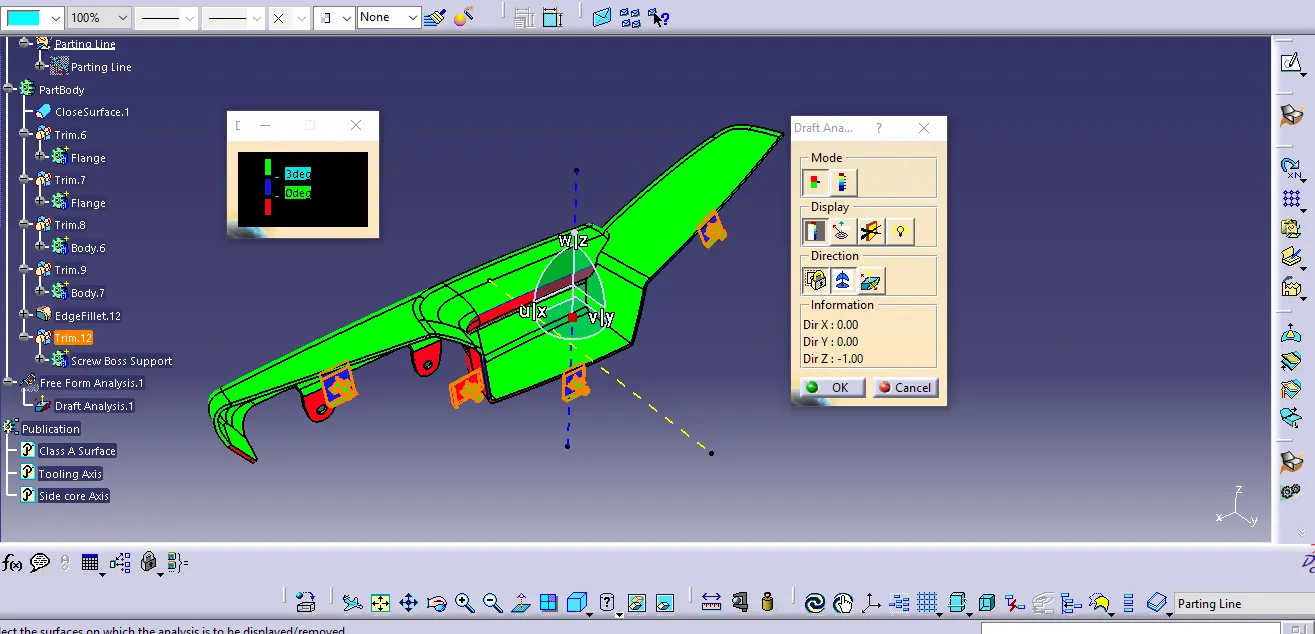
Side Core Axis:
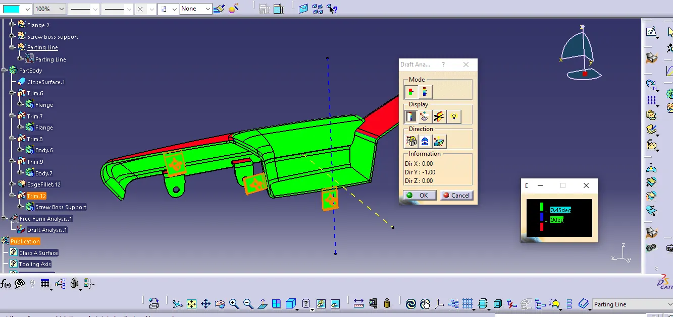 LOWER SUBSTRATE:-
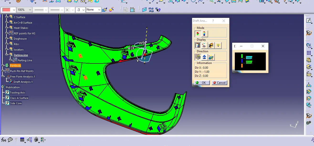
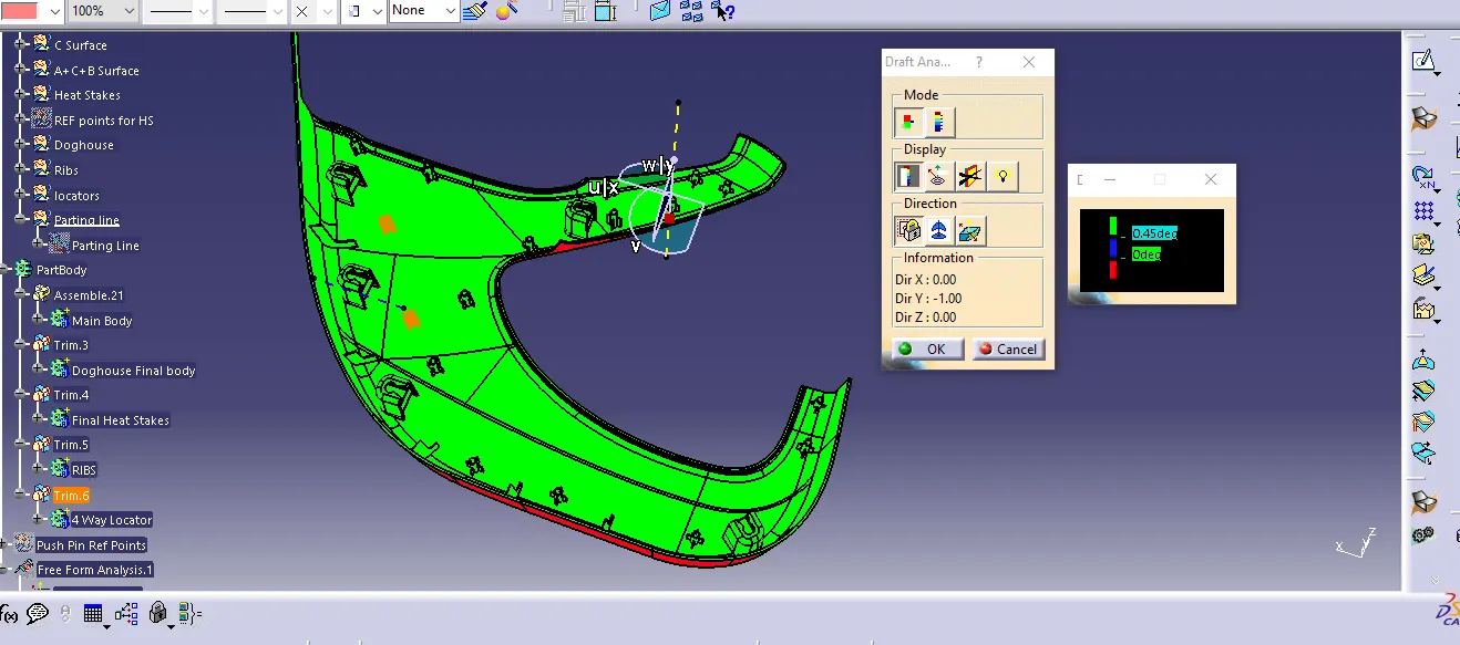
Side Core Axis
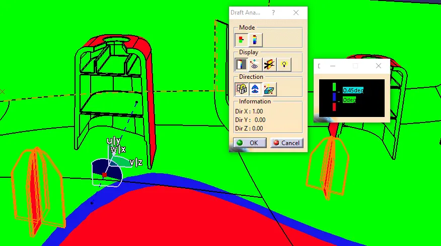
MAP POCKET UPPER :-
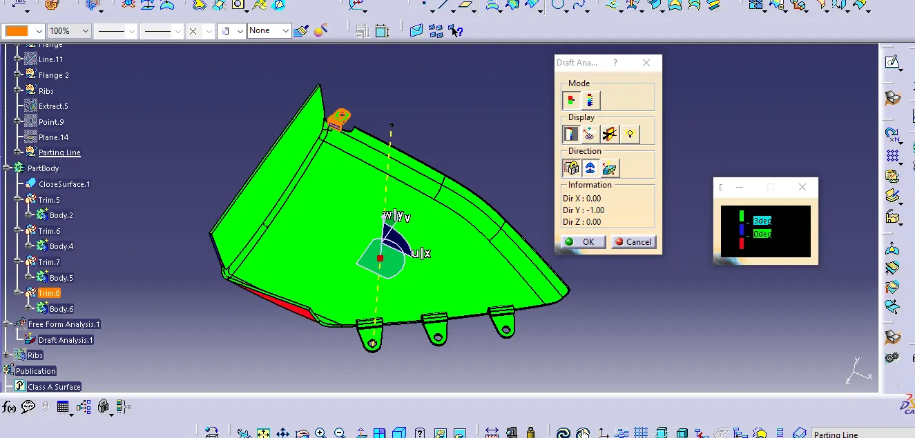
MAP POCKET LOWER:-
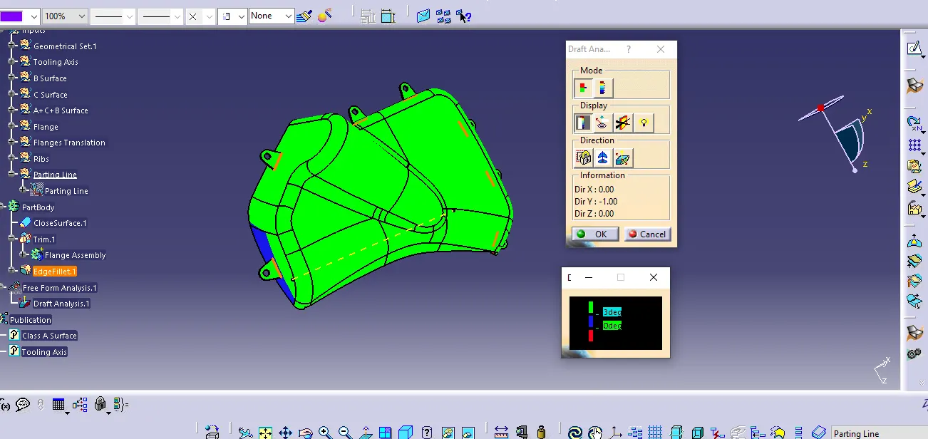
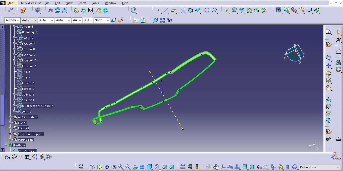
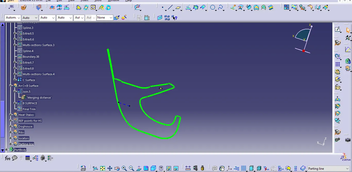
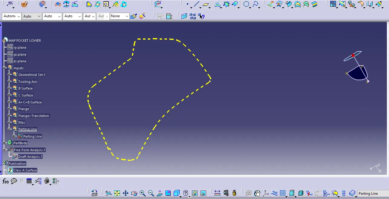
Parting Line:-
ARM REST:-
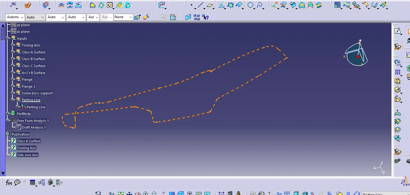
LOWER SUBSTRATE:-
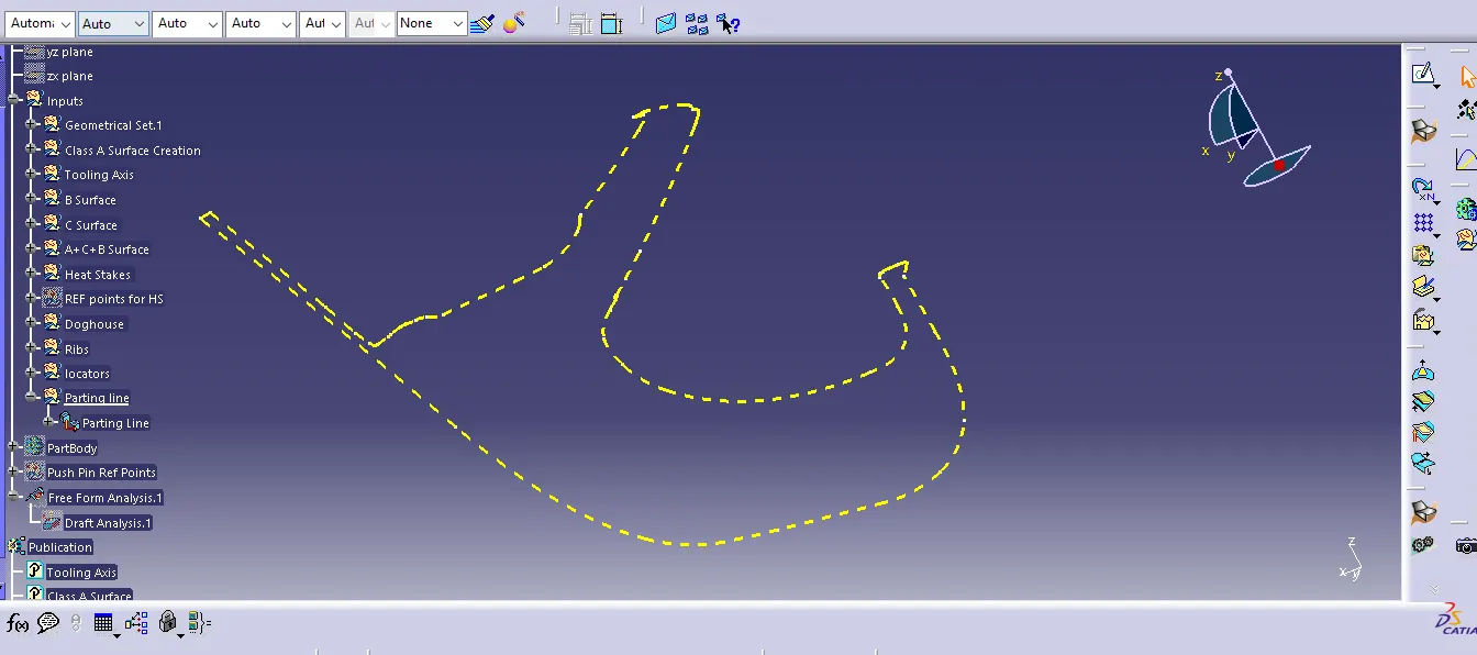
MAP POCKET UPPER :-
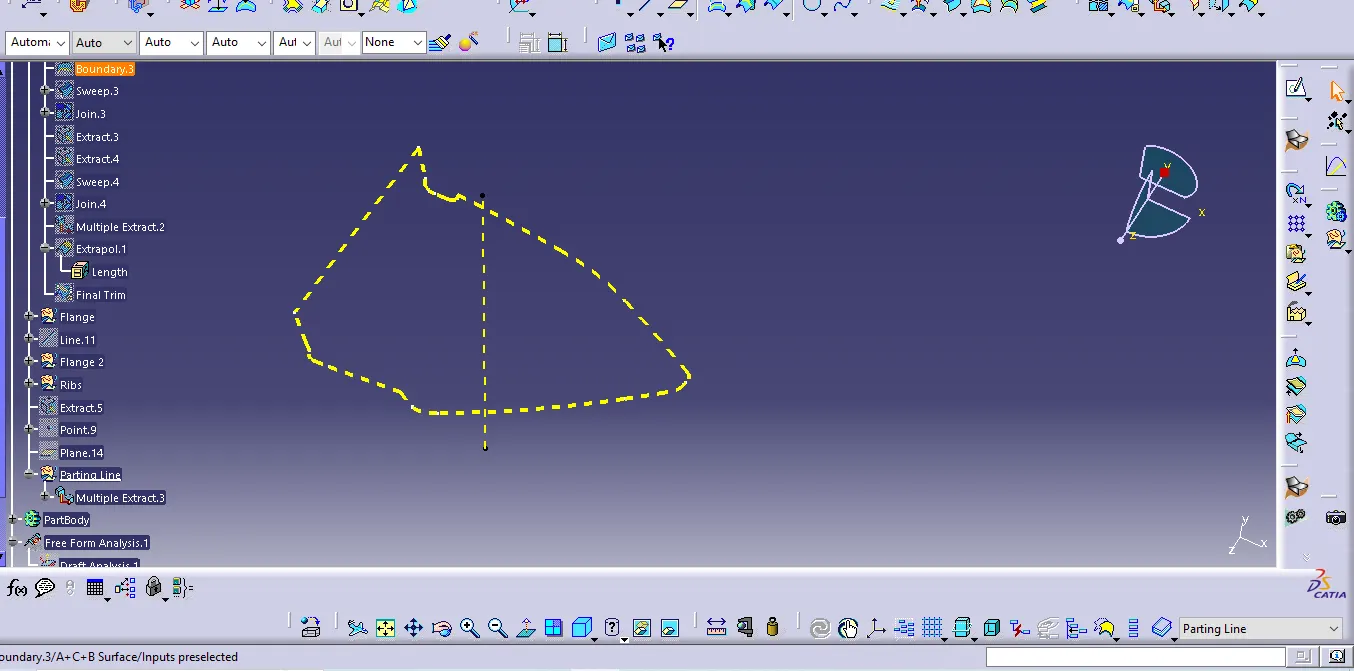
MAP POCKET LOWER:-
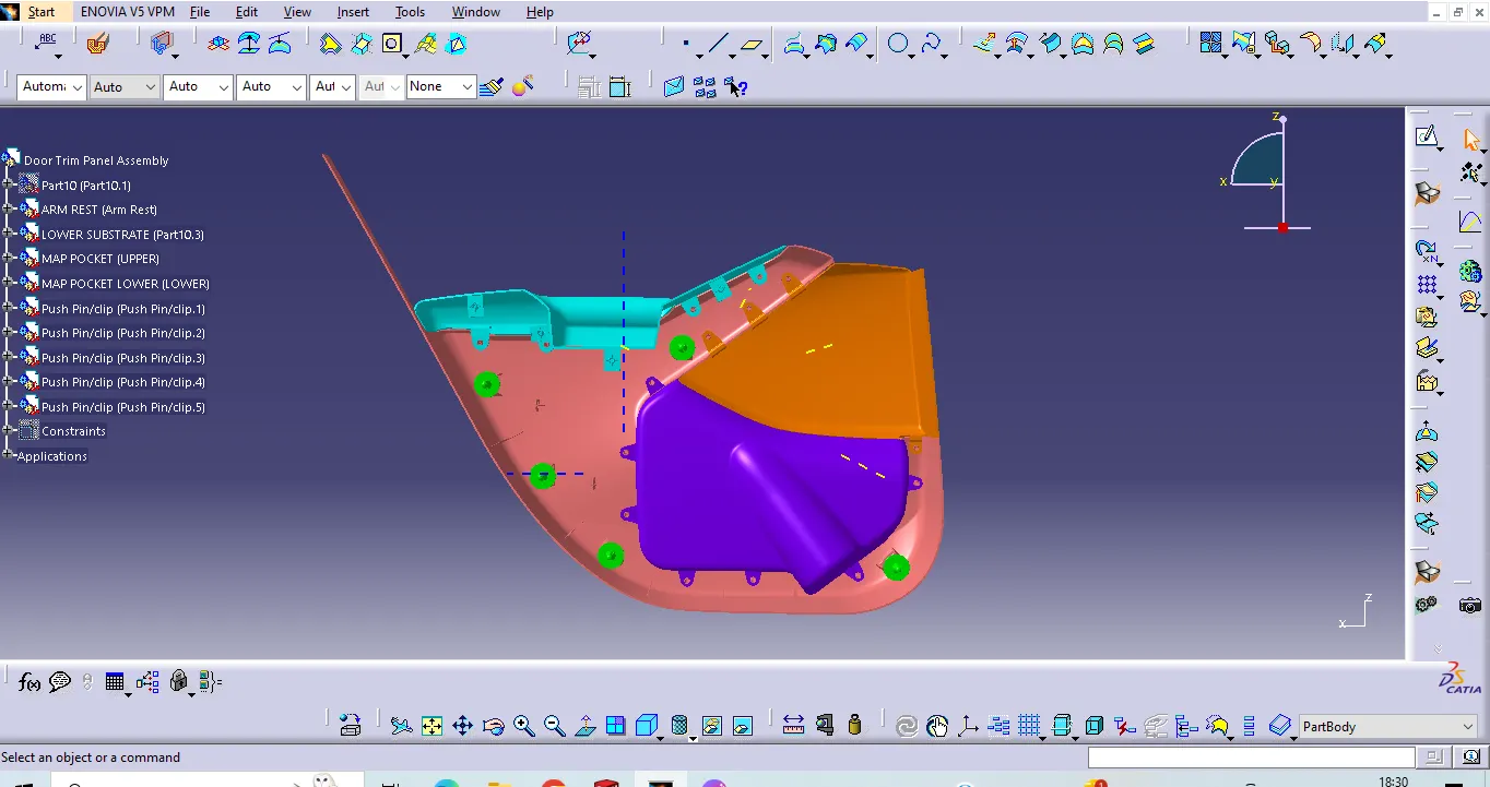
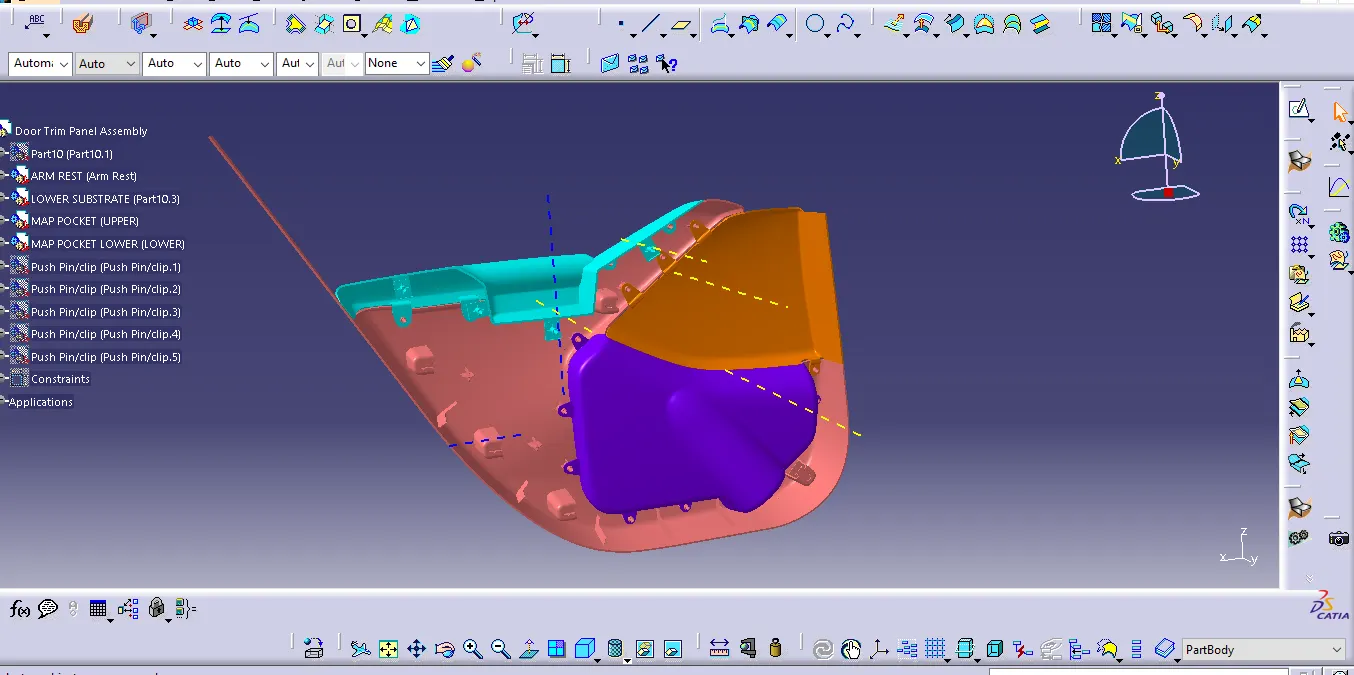
Door Trim Panel Assembly:
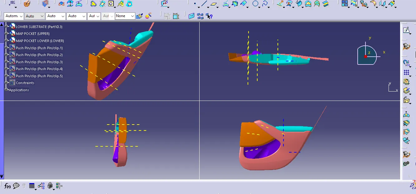
3D Assembly model in various orientations (Isometric, Front, Side, and Top View)
Conclusion:-
Developed a Door Trim panel is done,as shown below
Final Assembly