Week 12- Final project
Solution - A complete report and steps followed is mentioned below -
Given class Master section surface -
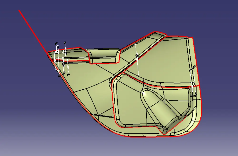
For development of complete door trim panel, we need to design each component individually with all standard rules. For which here we are providing different surface with different name and to design and understand easily.
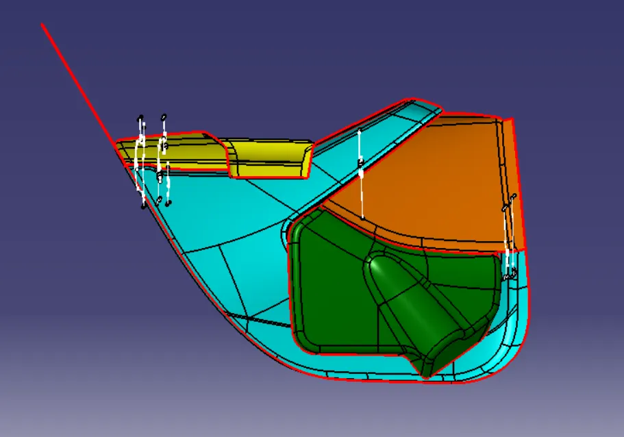
1. Arm rest (In yellow color)
2. Map pocket (in Orange color)
3. Bottle holder (in dark green color)
4. Lower substrate (in Cyan color)
Now we will design every part Individually by adding all the parts in a CATproduct file.
1. Arm rest
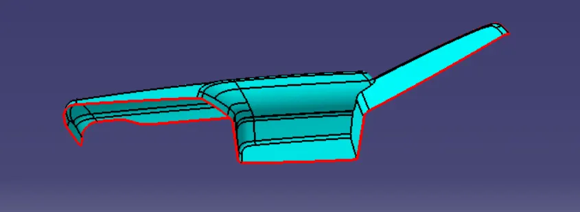
Given class A surface -

STEP 1: Check the connectivity of the Class A Surface to ensure that there is no gap between the component, using the join command.
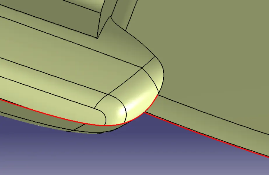
we found one improper patch so we resolved it hence got a improved Class A surface.
STEP 2: - Create Tooling Axis
Tooling axis -
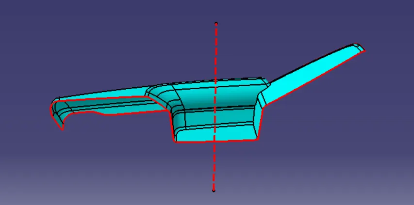
Tooling axis or Molding axis is the direction in which the core and cavity opens. It is basically the direction that the mold pulls apart. It is created using Bisecting method. Creating a tooling axis is necessary to provide draft angle and analyze them.
Bisecting Method to create Tooling Axis -
To decide the Tooling axis, the component should clear the tooling axis in the given specific direction. The first step is to visually check the component for the best tooling direction in all three x, y and z directions. In given class A surface we will use bisecting method.
In bisecting method tooling axis is created by taking a intersection on class a surface then take the 2 inclined line and performing bisecting line command over it, then we get a bisecting line which we call tooling axis. As shown below:
STEP 3 : - Draft analysis of class A surface -
For Draft analysis first we fix the draft compass axis with tooling axis then we give the draft angle and check for its feasibility of occurance which is shown by color grade as shown in picture below -
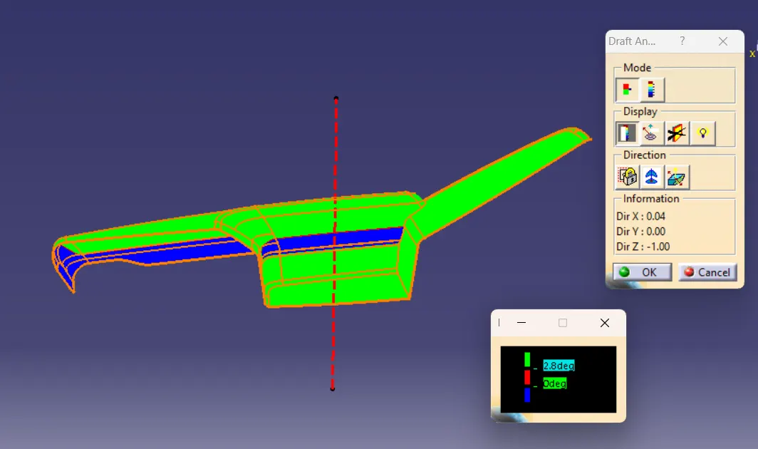
Here we are not getting all the surfaces fully drafted so side core Tooling axis is required which is shown below :-
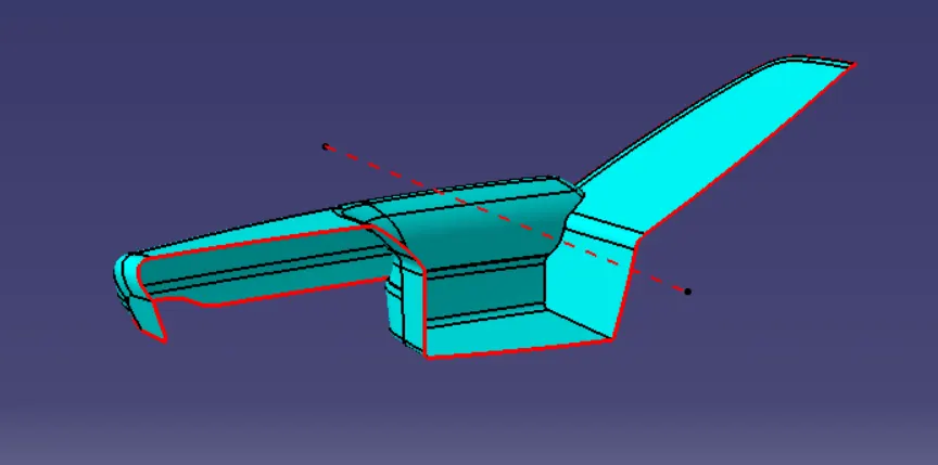
Draft analysis with respect to this side core tooling axis is shown below :-
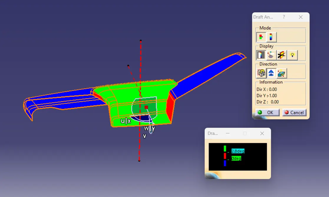
Hence we got all the surfaces drafted.
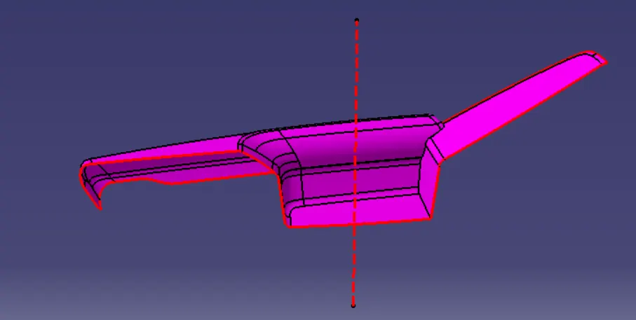
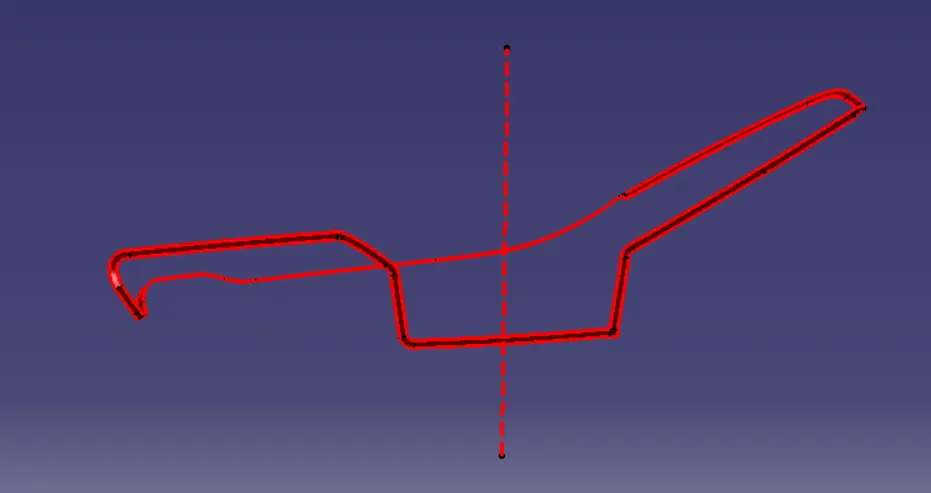
STEP 4 :- Creation of Class B and C surface -
This is done by using all necessary surface command which is attachted below in a CATPart file and the Screen shot of B and C surface is attached here below -
B surface -
C surface -
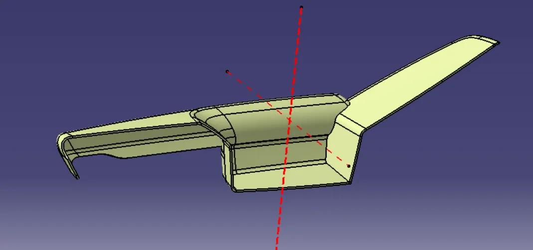
STEP 5 :- Complete Surface creation Using Class A , B and C surface -
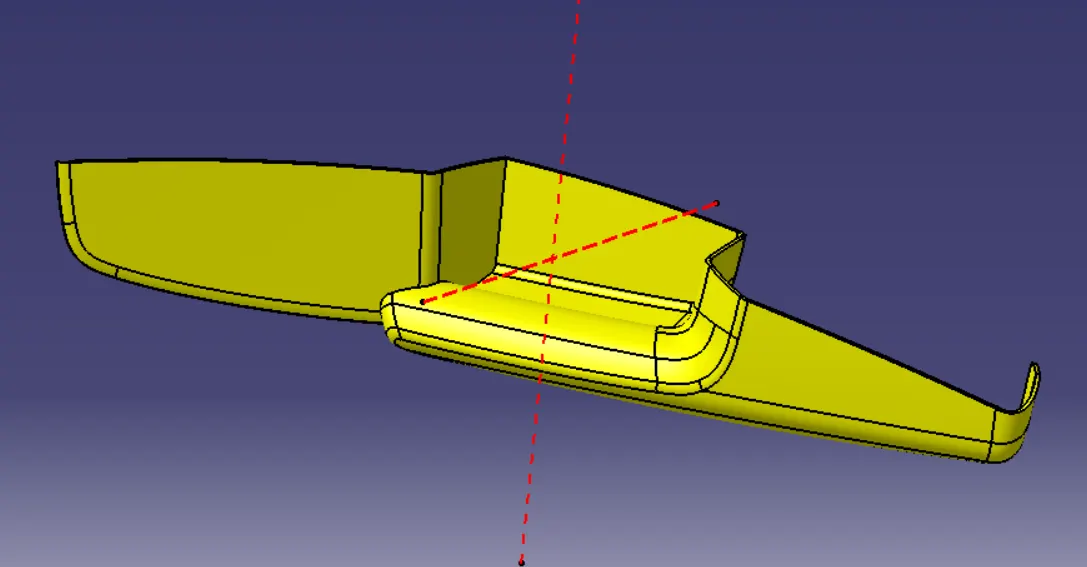
STEP 6 - Conversion of surface body into solid body using close surface command of part workbench-
STEP 7 - Creation of Mounting as shown in mastersection and as per design rules -
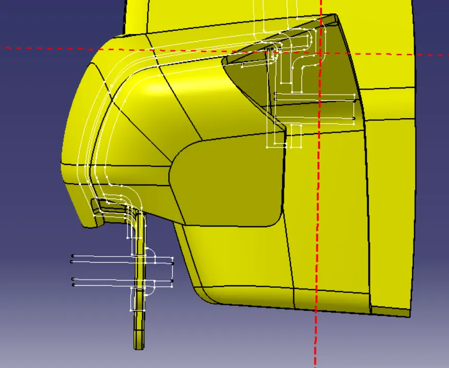
The location and number of mounting is depends upon rules and as per our design, which is placed as below shown :-
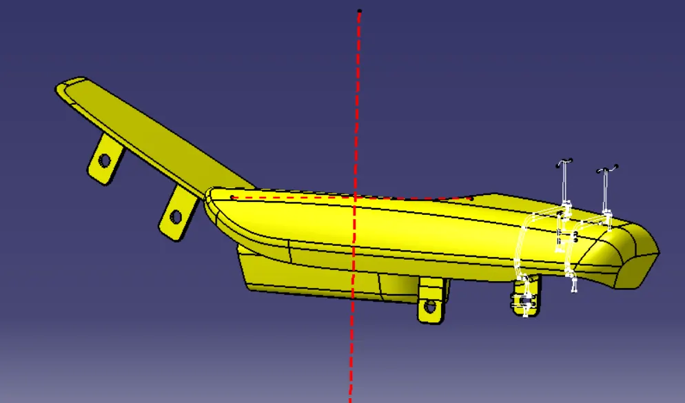
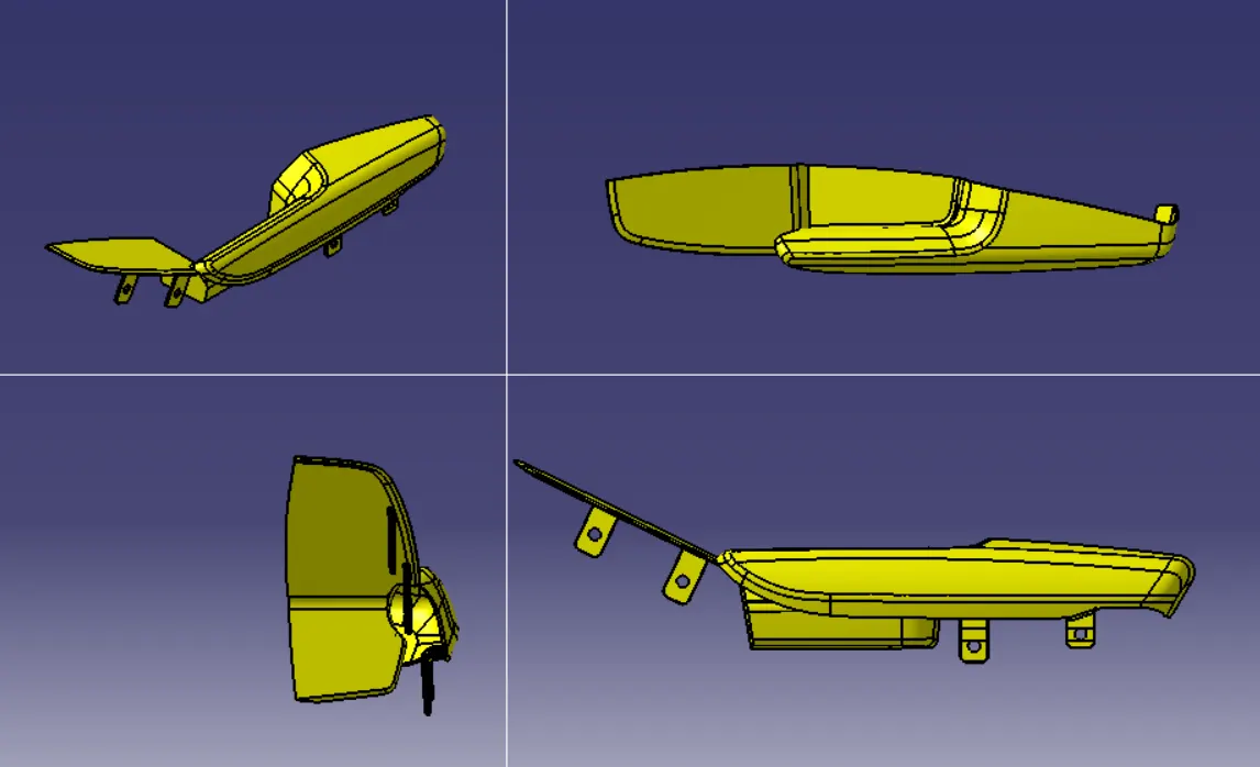
STEP 8 - Complete assembled final body in all views -
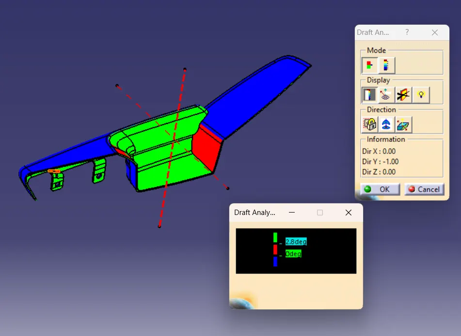
STEP 9 :- Draft analysis of final solid -
From main tooling axis-
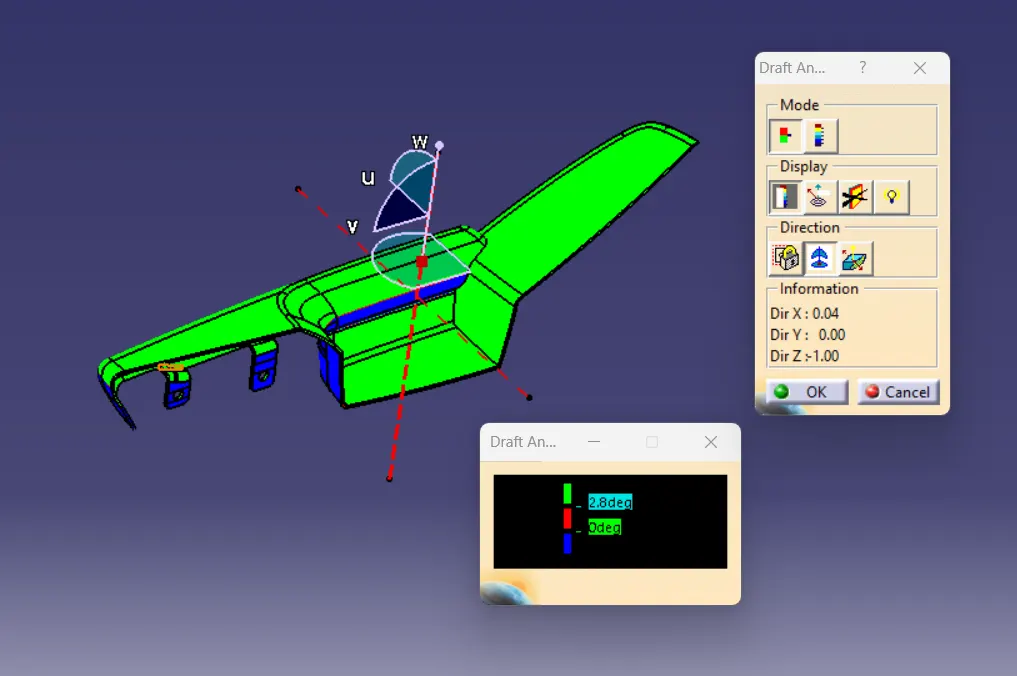
From side core tooling axis -
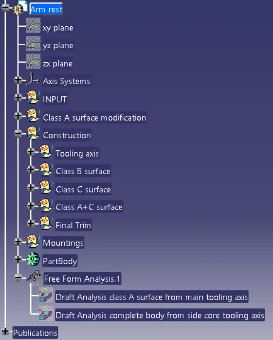
Screenshot of tree structure is attatched below here -
2. Map Pocket -
Given class A surface -
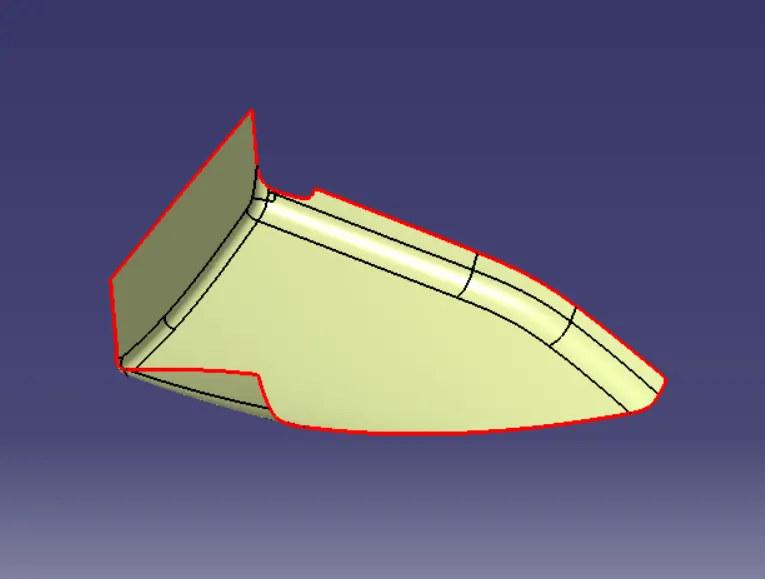
STEP 1: Check the connectivity of the Class A Surface to ensure that there is no gap between the component, using the join command.
STEP 2: - Create Tooling Axis
Tooling axis -
Tooling axis or Molding axis is the direction in which the core and cavity opens. It is basically the direction that the mold pulls apart. It is created using Bisecting method. Creating a tooling axis is necessary to provide draft angle and analyze them.
Bisecting Method to create Tooling Axis -
To decide the Tooling axis, the component should clear the tooling axis in the given specific direction. The first step is to visually check the component for the best tooling direction in all three x, y and z directions.
In bisecting method tooling axis is created by taking a intersection on class a surface then take the 2 inclined line and performing bisecting line command over it, then we get a bisecting line which we call tooling axis.
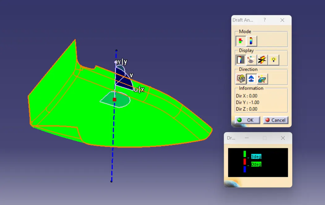
In the given Class A surface Y direction is giving fully draft to all the surfaces so it is taken as tooling axis.
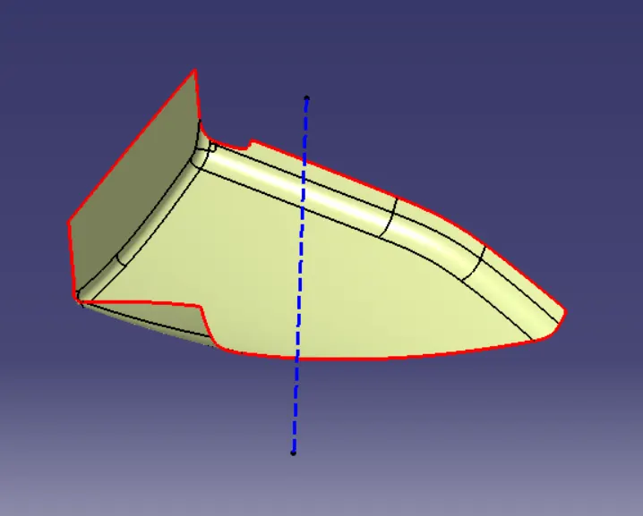
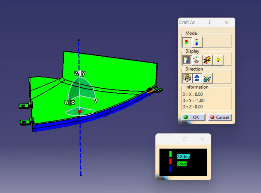
STEP 3 : - Draft analysis of class A surface -
For Draft analysis first we fix the draft compass axis with tooling axis then we give the draft angle and check for its feasibility of occurance which is shown by color grade as shown in picture below -
STEP 4 :- Creation of Class B and C surface -
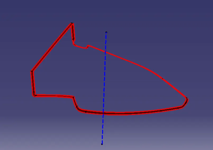
This is done by using all necessary surface command which is attachted below in a CATPart file and the Screen shot of B and C surface is attached here below -
B surface -
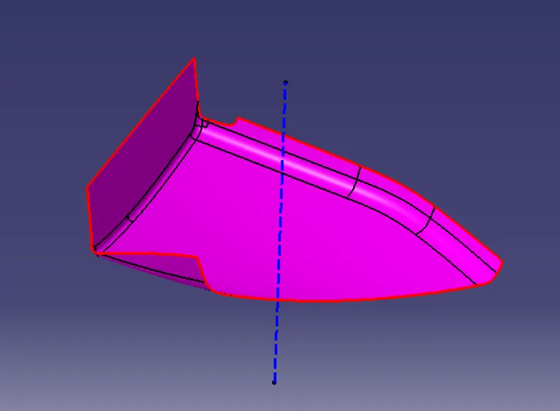
C surface -
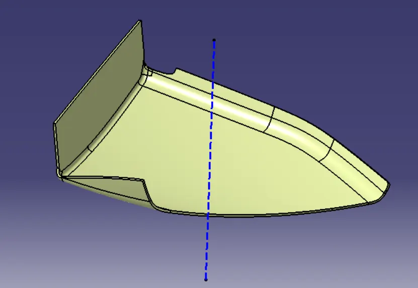
STEP 5 :- Complete Surface creation Using Class A , B and C surface -
STEP 6 - Conversion of surface body into solid body using close surface command of part workbench-
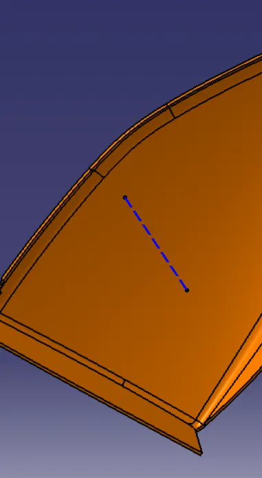
STEP 7 - Creation of Mounting as shown in mastersection and as per design rules -
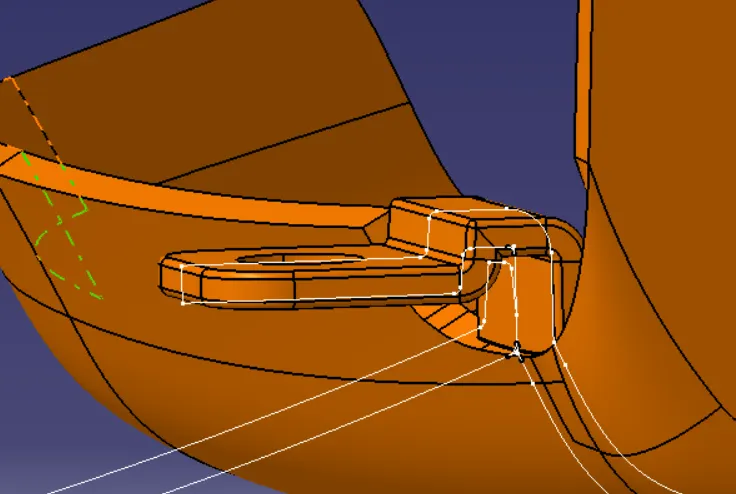
The location and number of mounting is depends upon rules and as per our design, which is placed as below shown :-
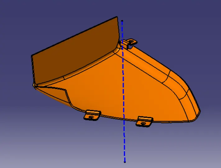
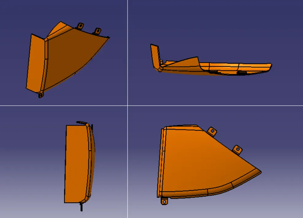
STEP 8 - Complete assembled final body in all views -
STEP 9 :- Draft analysis of final solid -
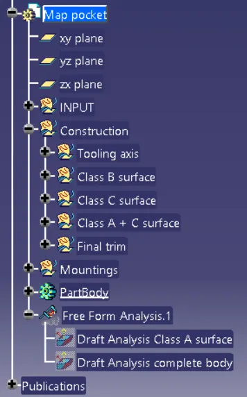
Screenshot of tree structure is attatched below here -
3. Bottle holder :-
Given class A surface -
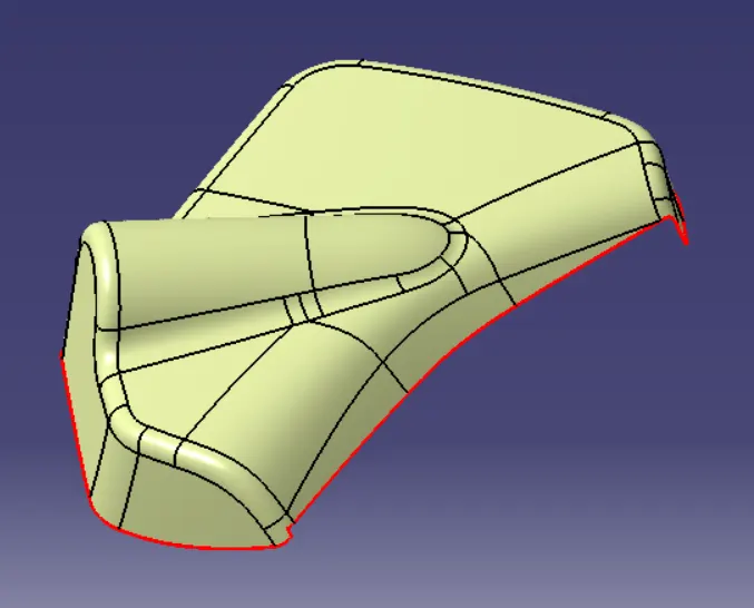
STEP 1: Check the connectivity of the Class A Surface to ensure that there is no gap between the component, using the join command.
STEP 2: - Create Tooling Axis
Tooling axis -
Tooling axis or Molding axis is the direction in which the core and cavity opens. It is basically the direction that the mold pulls apart. It is created using Bisecting method. Creating a tooling axis is necessary to provide draft angle and analyze them.
Bisecting Method to create Tooling Axis -
To decide the Tooling axis, the component should clear the tooling axis in the given specific direction. The first step is to visually check the component for the best tooling direction in all three x, y and z directions..
In bisecting method tooling axis is created by taking a intersection on class a surface then take the 2 inclined line and performing bisecting line command over it, then we get a bisecting line which we call tooling axis. As shown below:
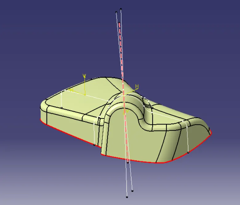
STEP 3 : - Draft analysis of class A surface -
For Draft analysis first we fix the draft compass axis with tooling axis then we give the draft angle and check for its feasibility of occurance which is shown by color grade as shown in picture below -
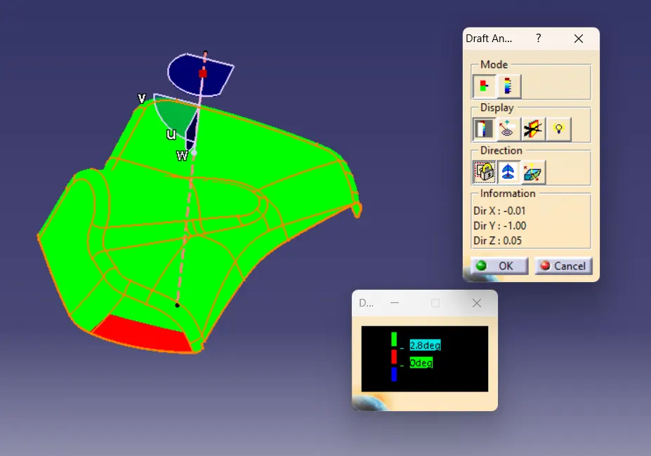
After applying bisecting method also we are getting some undeafted patches as shown above due to error of class A surface which will also reflect in our final solid body.
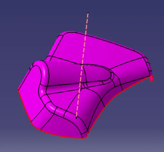
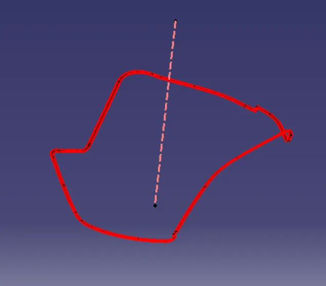
STEP 4 :- Creation of Class B and C surface -
This is done by using all necessary surface command which is attachted below in a CATPart file and the Screen shot of B and C surface is attached here below -
B surface -
C surface -
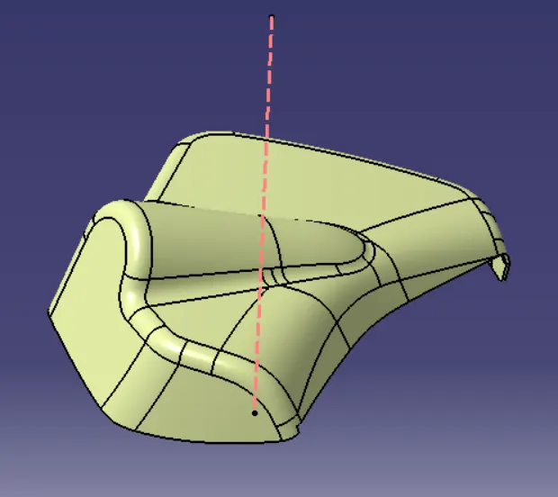
STEP 5 :- Complete Surface creation Using Class A , B and C surface -
STEP 6 - Conversion of surface body into solid body using close surface command of part workbench-
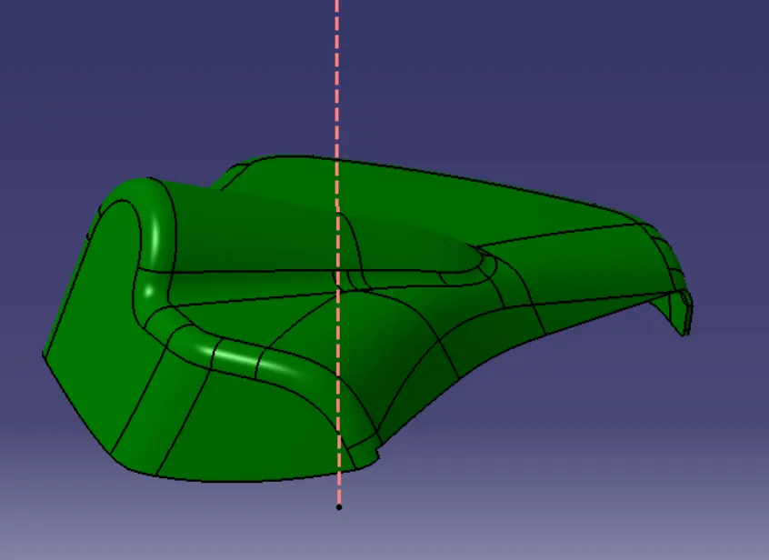
STEP 7 - Creation of Mounting according to our design and as per design rules -
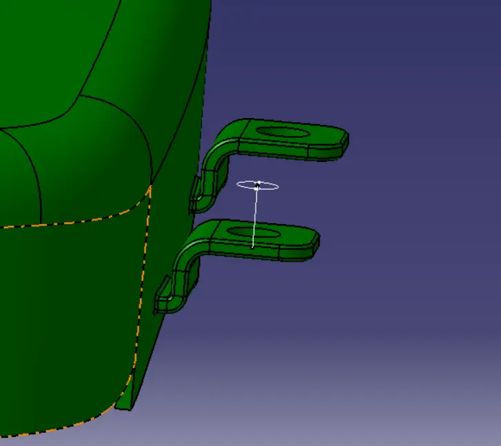
The location and number of mounting is depends upon rules and as per our design, which is placed as below shown :-
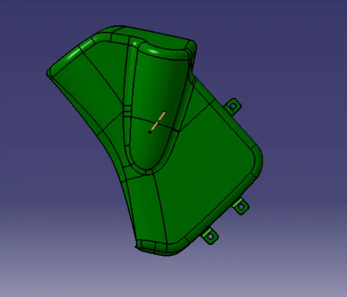
STEP 8 - Complete assembled final body in all views -
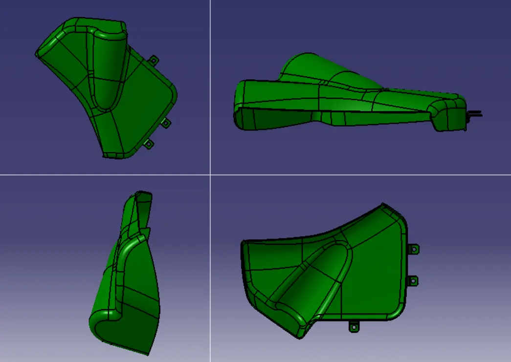
STEP 9 :- Draft analysis of final solid -
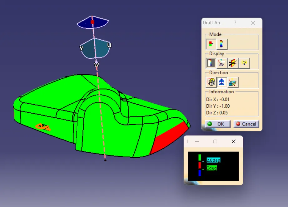
Some undrafted patches occured due to error of Class A surface.
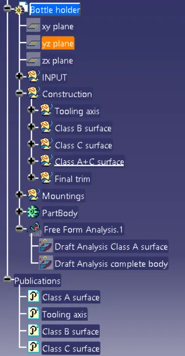
Screenshot of tree structure is attatched below here -
4. Lower Substrate :-
Given class A surface -
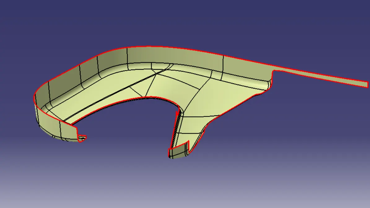
STEP 1: Check the connectivity of the Class A Surface to ensure that there is no gap between the component, using the join command.
STEP 2: - Create Tooling Axis
Tooling axis -
Tooling axis or Molding axis is the direction in which the core and cavity opens. It is basically the direction that the mold pulls apart. It is created using Bisecting method. Creating a tooling axis is necessary to provide draft angle and analyze them.
Bisecting Method to create Tooling Axis -
To decide the Tooling axis, the component should clear the tooling axis in the given specific direction. The first step is to visually check the component for the best tooling direction in all three x, y and z directions.
In the given Class A surface Y direction is giving fully draft to all the surfaces so it is taken as tooling axis.
In bisecting method tooling axis is created by taking a intersection on class a surface then take the 2 inclined line and performing bisecting line command over it, then we get a bisecting line which we call tooling axis.
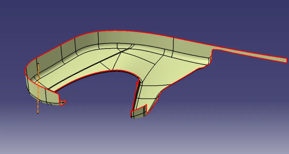
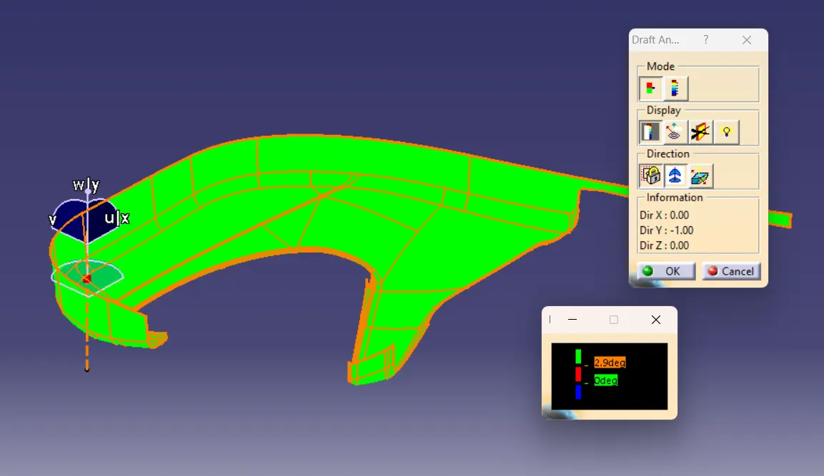
STEP 3 : - Draft analysis of class A surface -
For Draft analysis first we fix the draft compass axis with tooling axis then we give the draft angle and check for its feasibility of occurance which is shown by color grade as shown in picture below -
STEP 4 :- Creation of Class B and C surface -
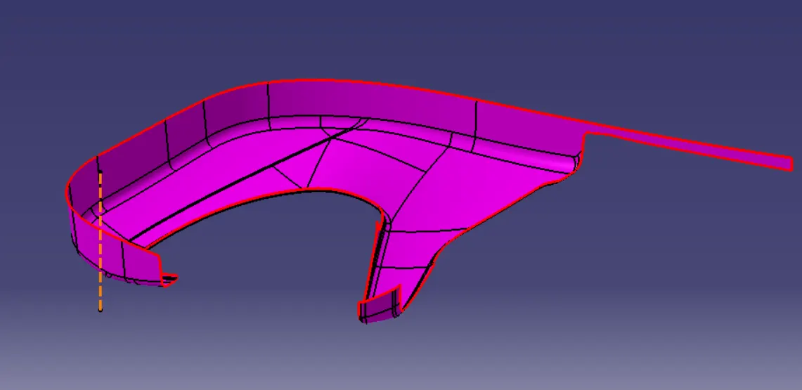
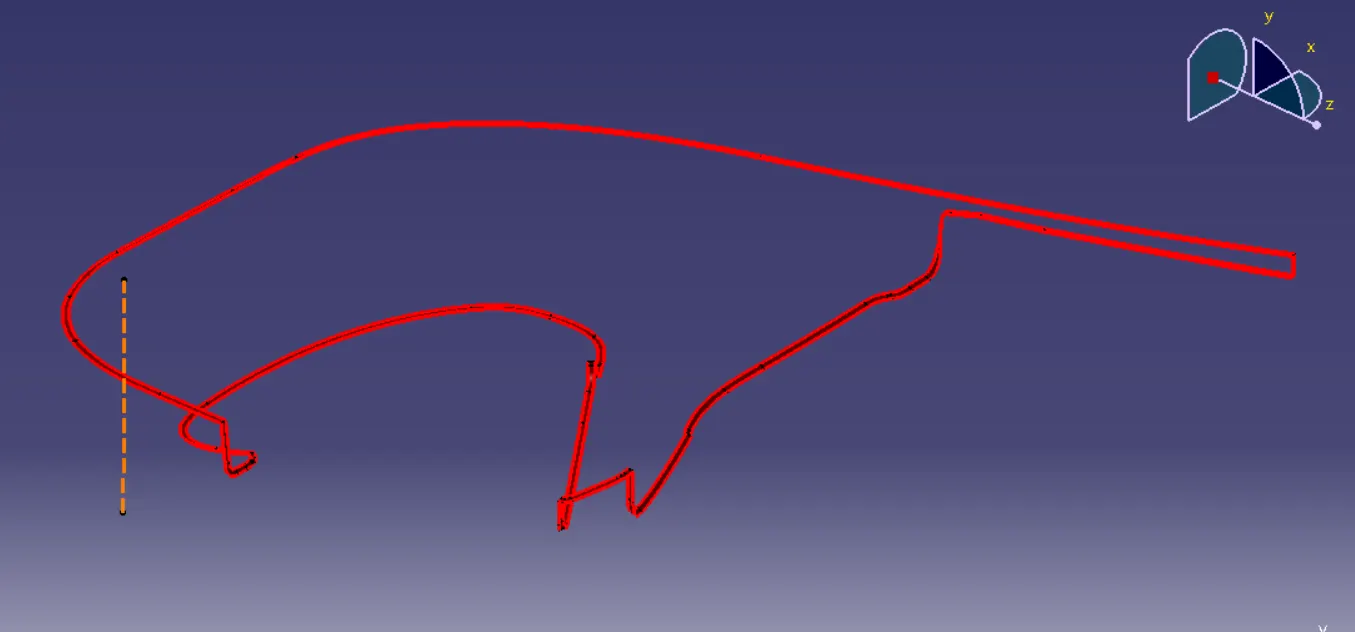
This is done by using all necessary surface command which is attachted below in a CATPart file and the Screen shot of B and C surface is attached here below -
B surface -
C surface -
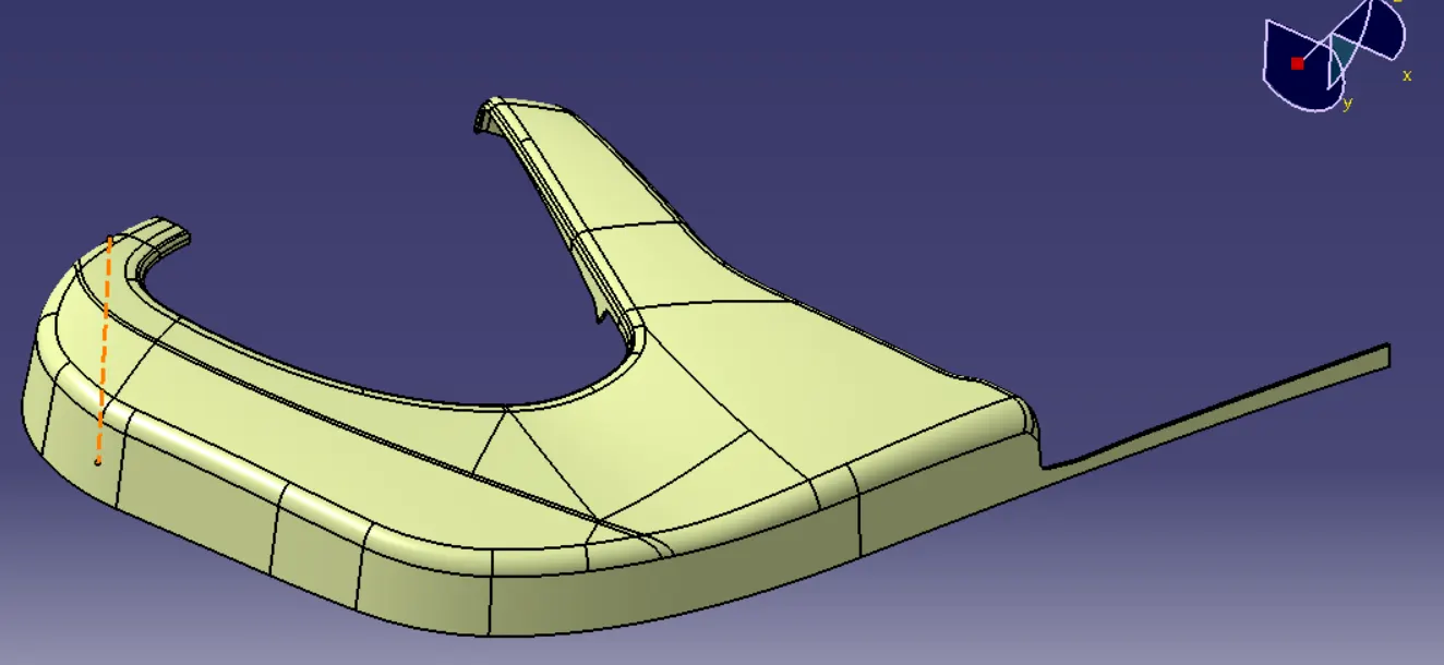
STEP 5 :- Complete Surface creation Using Class A , B and C surface -
STEP 6 - Conversion of surface body into solid body using close surface command of part workbench-
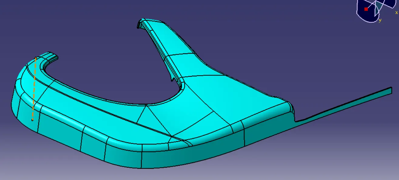
STEP 7 - Creation of B side features as per mastersection and design rules -
Heat stakes -
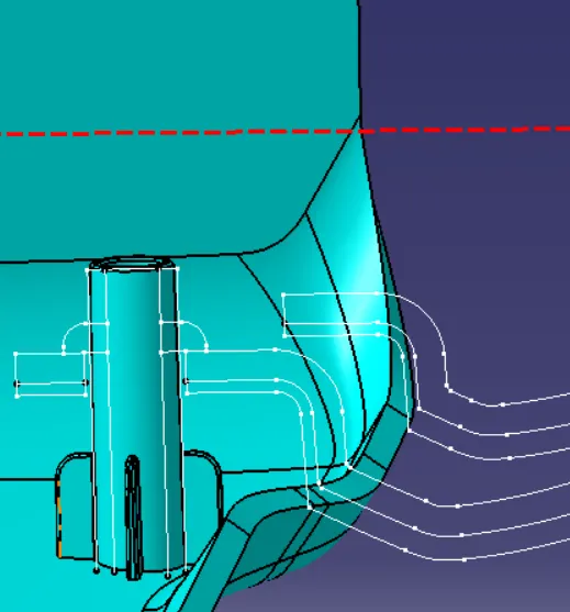
Dog House -
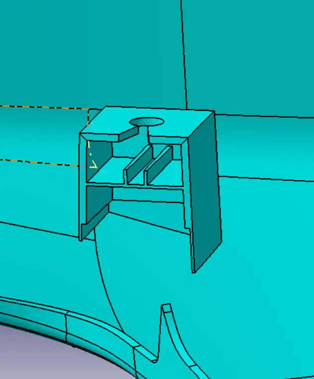
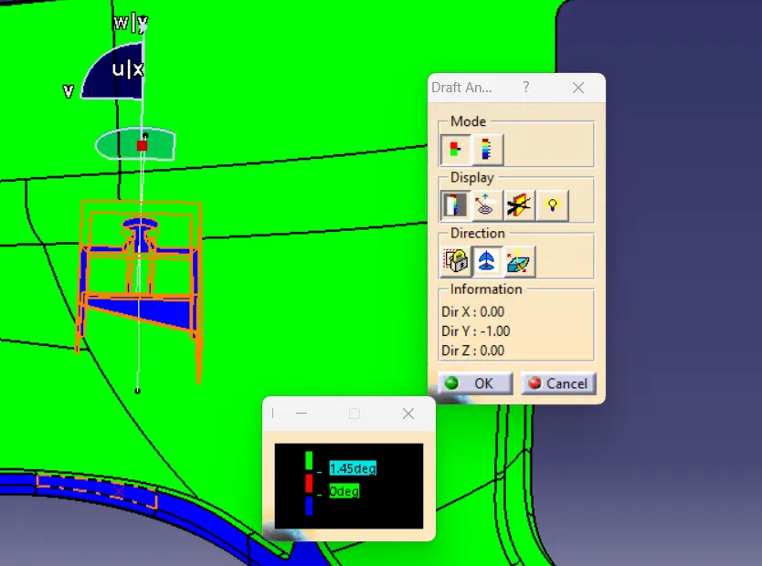
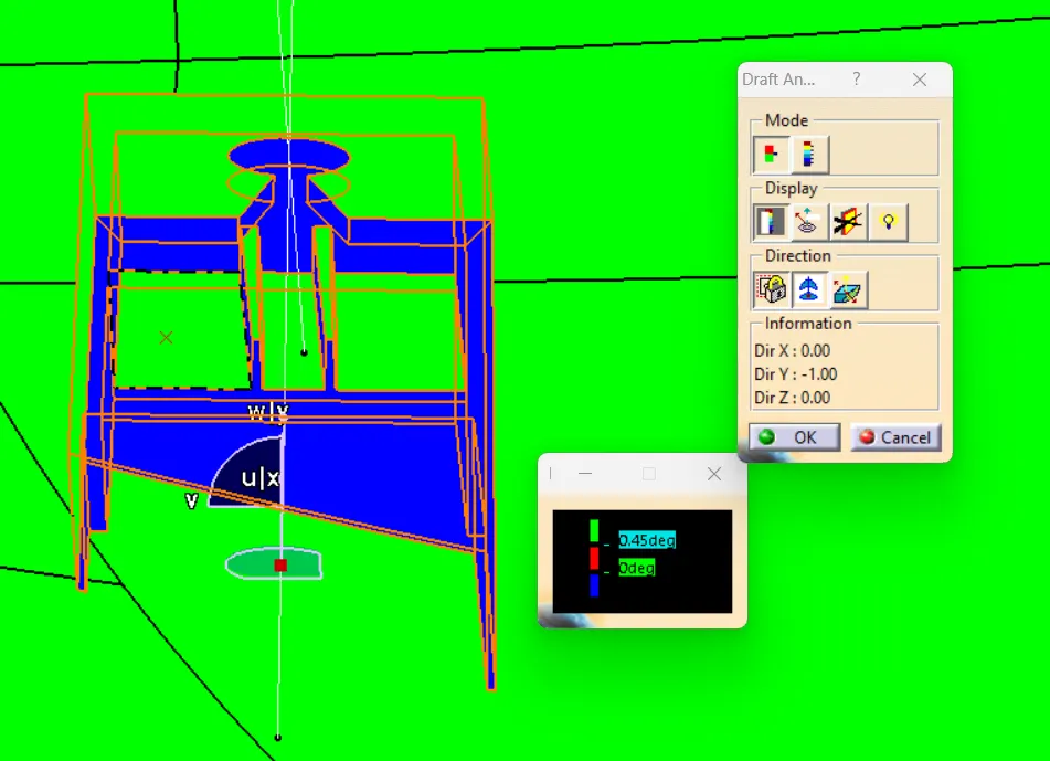
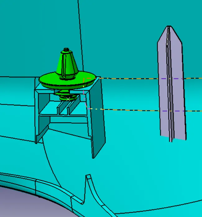
Here In this dog house, push pin will be attached for door panel attachment. For which locators will be used, but we are not having the door panel design for locators proper location hence we are not including locators in our lower substrate design. But below i am giving approximate view only of locator that can be designed -
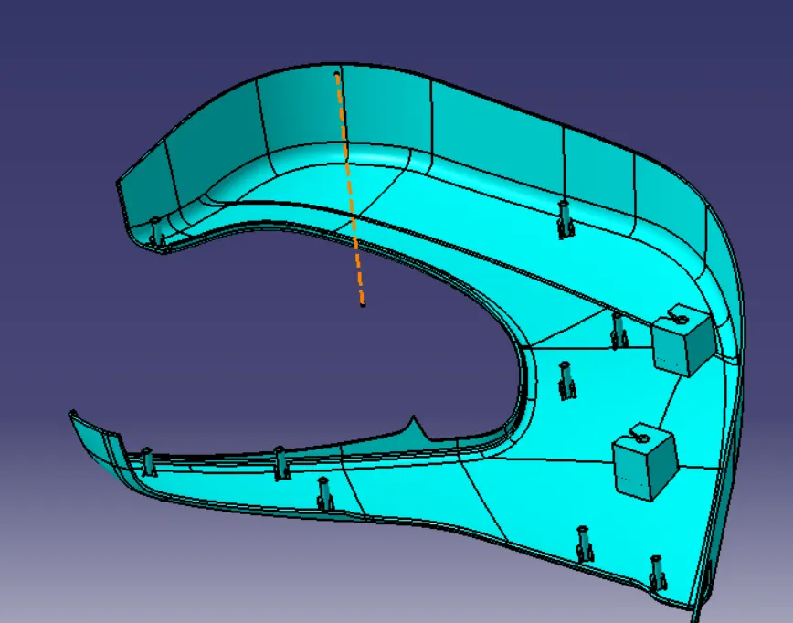
The location and number of B side features are depend upon rules and as per our design, which is placed as below shown :-
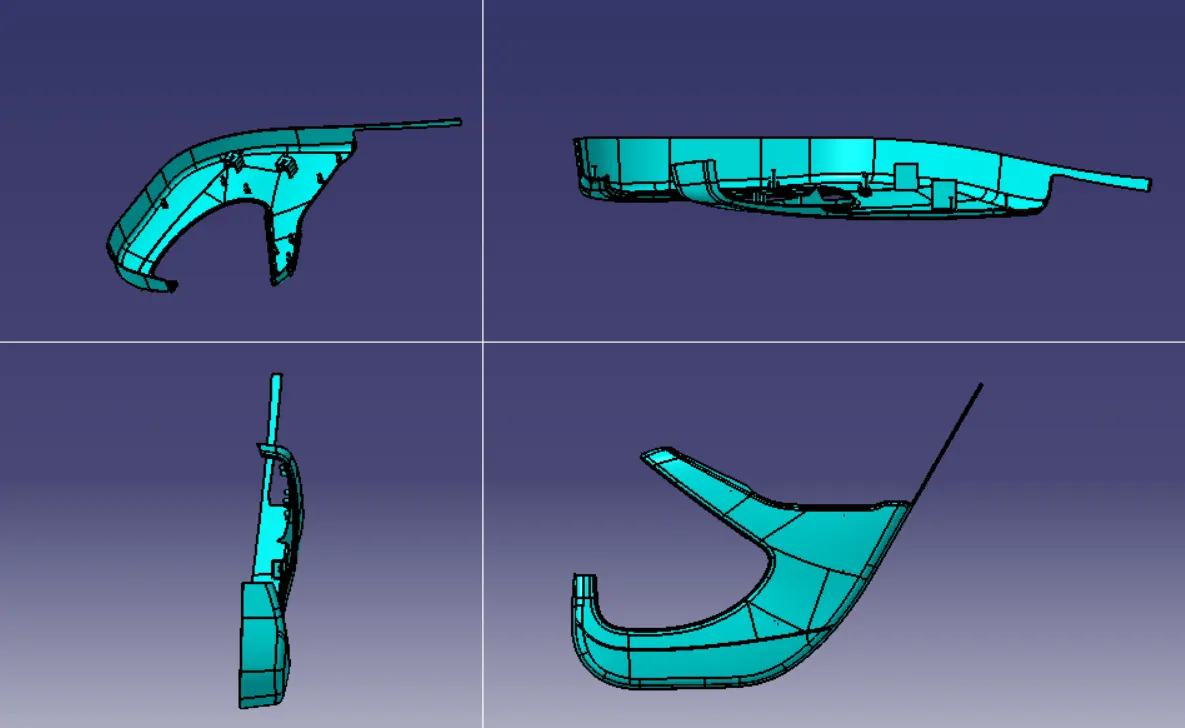
STEP 8 - Complete assembled final body in all views -
STEP 9 :- Draft analysis of final solid -
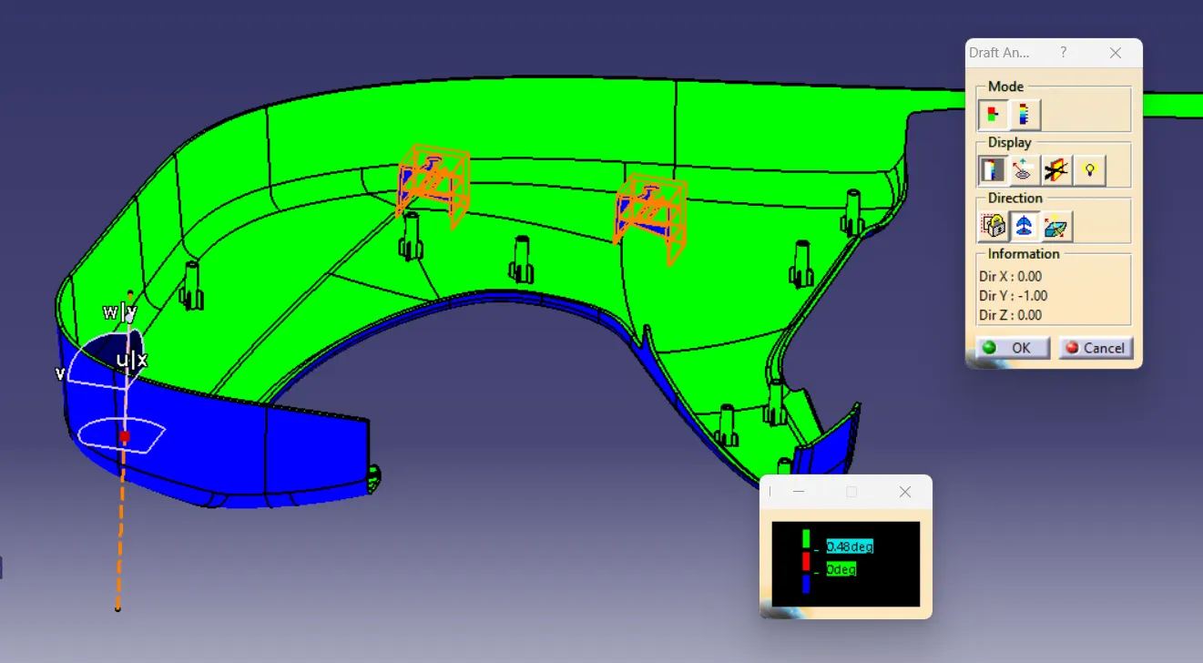
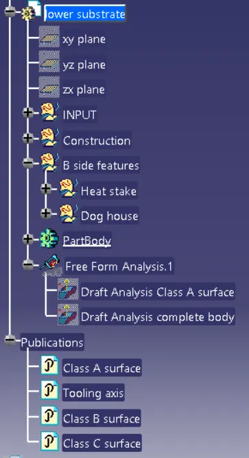
Screenshot of tree structure is attatched below here -
Here we are completed with all parts design.
Now we will fix the lower substrate in assembly and place the push pin with constrains-
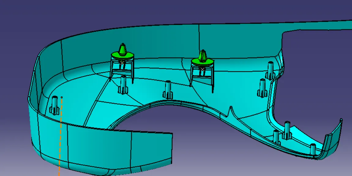
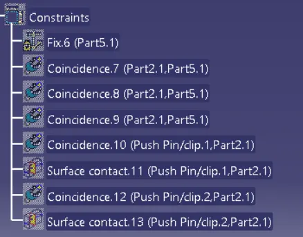
The final view of complete design and tree structure is attached below-
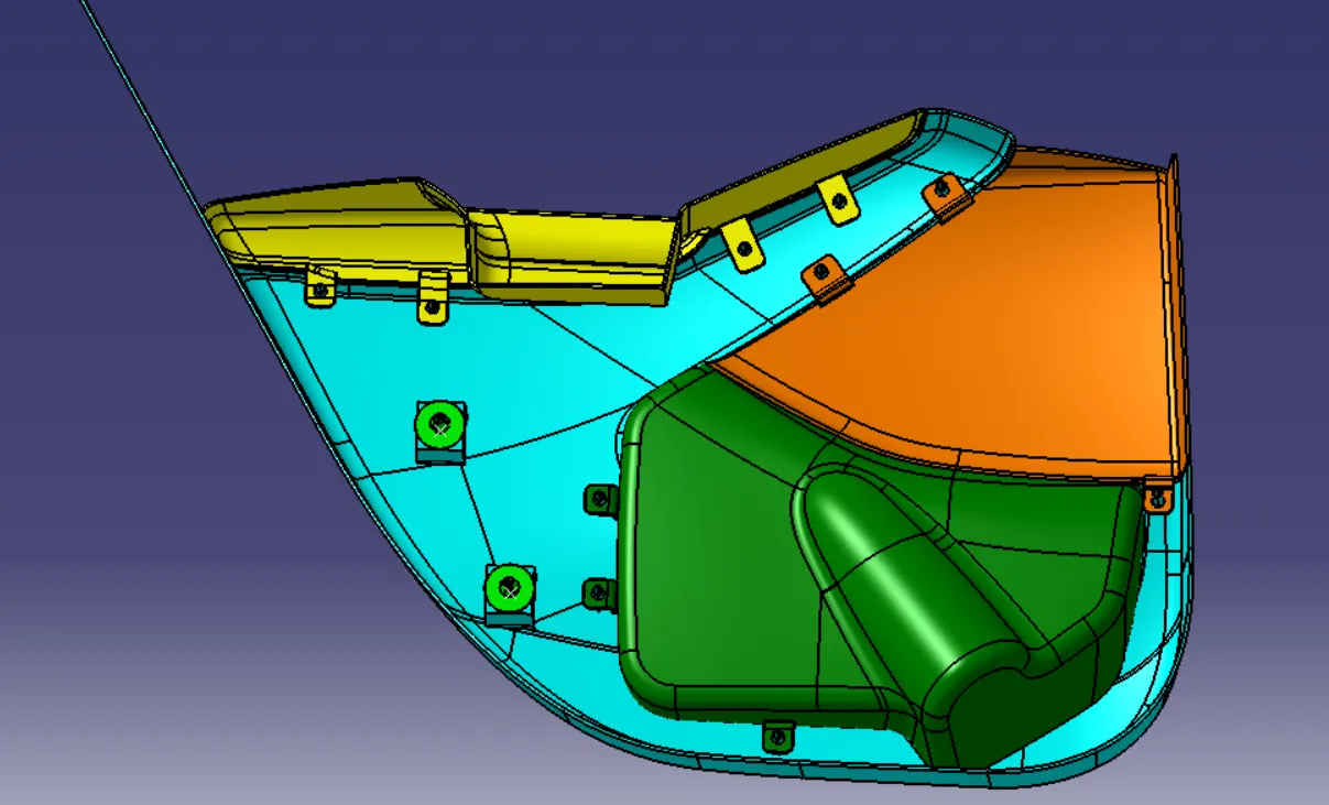
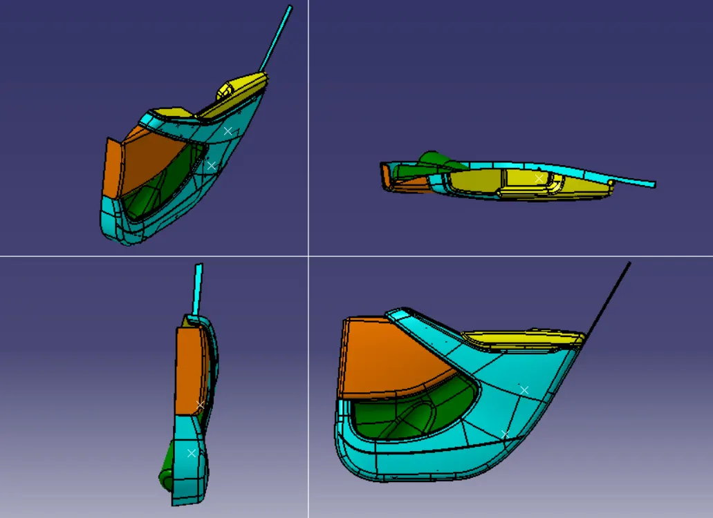
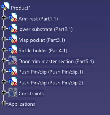
All CATpart and CATproduct file are attached below as single zipped file.