Week 12- Final project
A REPORT ON FINAL PROJECT (DOOR IP DESIGN )
AIM:
To create a CAD model considering the OEM standards from the Class-A surface of a Door Panel.
INTRODUCTION:
Door panels serve as an interface between the interior of the car and the inner workings of the door, and between vehicle occupants and the door. They are expected to meet a variety of design specifications regarding safety, aesthetics, and functionality. In addition, they are expected to continue the material theme of the dashboard and pillars while concealing intricate electrical and mechanical components for operating locks, windows, and other features. The door panel has evolved from a simple two-part system of latch and simple winding mechanism to a more sophisticated enclosure. Doors currently have an inner full-width panel consisting of electronic windows, central locking system, and speakers. These panels typically consist of a foamed core covered with either textiles or plastics.
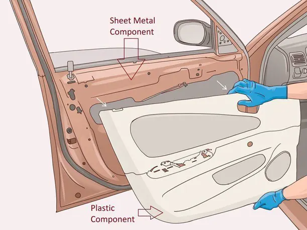
Overview of Door Trim Panel:
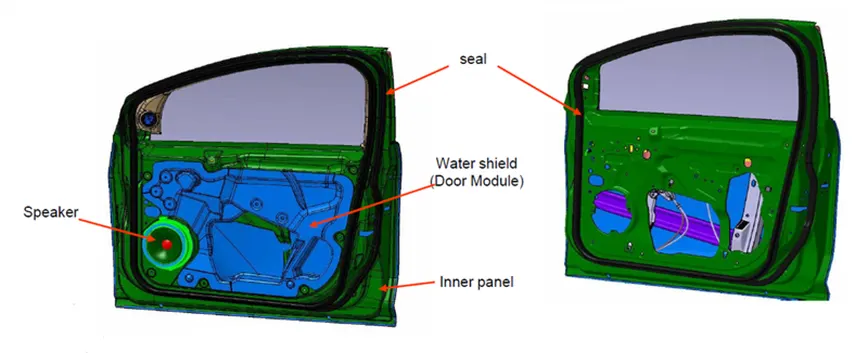
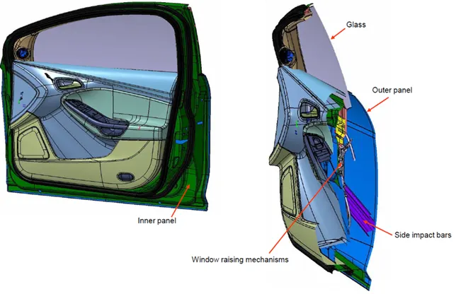
Class-A Surface:
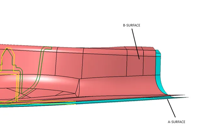
A-class surfaces are those aesthetic/ free form surfaces, which are visible to us (interior/exterior), having an optimal aesthetic shape and high surface quality. Mathematically class-A surfaces are those surfaces which are curvature continuous while providing the simplest mathematical representation needed for the desired shape/form and does not have any undesirable waviness. Products are not only designed considering the functionality but special consideration is given to its form/aesthetics which can bring a desire in one’s mind to own that product. This is only possible with high-class finish and good forms. This is the reason why in design industries Class-A surfaces are given more importance. In automotive design, a class-A surface is any of a set of freeform surfaces of high efficiency and quality. Although, strictly, it is nothing more than saying the surfaces have curvature and tangency alignment – to ideal aesthetical reflection quality, many people interpret class A surfaces to have G2 (or even G3) curvature continuity to one another (see free form surface modelling). Class A surfacing is done using computer-aided industrial design applications. Class-A surface modellers are also called "digital sculptors" in the industry. Industrial designers develop their design styling through the A-Surface, the physical surface the end user can feel, touch, see etc.
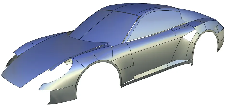
Class-B Surface:
Class-B surfaces are the secondary surfaces that can be seen sometimes, but are less important, such as the inside of your glovebox, ash tray, etc. These must be smooth and "error-free" as well, but are not held to the standards that class-A surface.
Class-C Surface:
Class C surfaces are the backside surfaces that can have tool marks, flash and other imperfections without hurting appearance, function, etc.
Plastic Part:
When designing parts for injection molding ,the manufacturing process is an important consideration. Injection molding is a process in which solid thermoplastic resin pellets are melted, injected into a mold, and then cooled back to a solid state in a new form. During both the injection and cooling stages of the manufacturing process, there are several factors that may affect the quality of the final product and the repeatability of the manufacturing process. Although it is not always possible to follow all recommendations, outlined on the following pages are some of the most fundamental guidelines when designing parts for injection molding.
Injection Molding Materials:
Materials Selection:
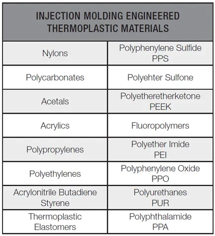
Many types of thermoplastic materials are available. Selection depends on the specific application. The chart below shows some of the most common materials being used.
B-Side Features:
Boss:
Bosses are used to facilitate the registration of mating parts, for attaching fasteners such as screws, or for accepting threaded inserts.
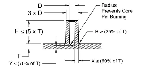
Wall thicknesses for bosses should be less than 60 percent of the nominal wall to minimize sinking. However, if the boss is not in a visible area, then the wall thickness can be increased to allow for increased stresses imposed by self-tapping screws.
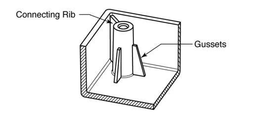
The base radius should be a minimum of 0.25 X thickness. Bosses can be strengthened by incorporating gussets at the base or by using connecting ribs attaching to nearby walls.
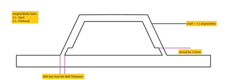
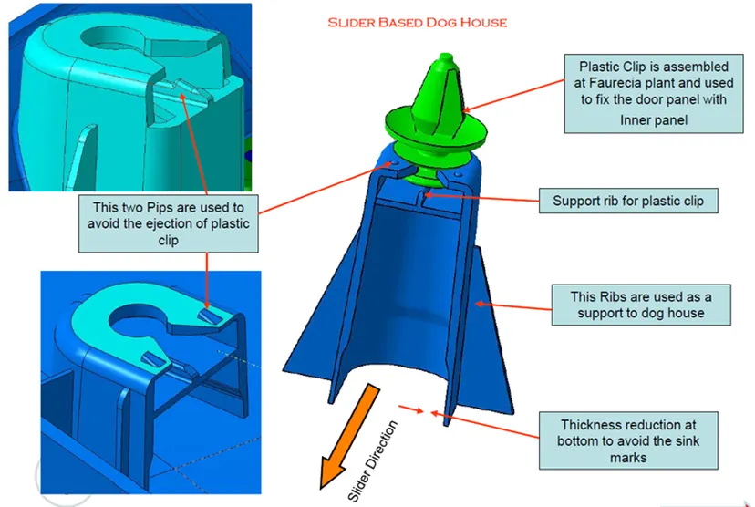
Dog House:
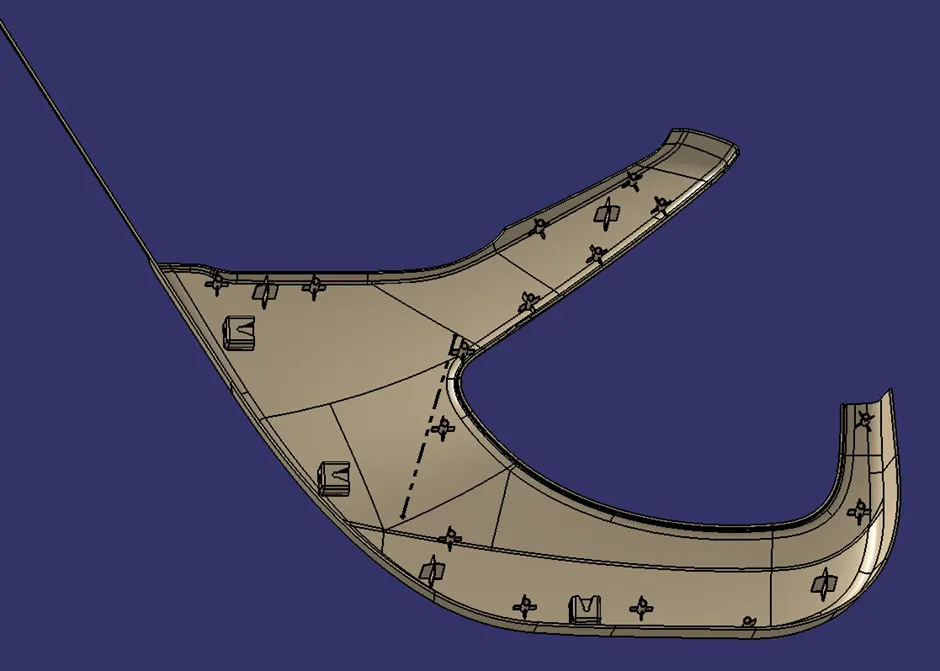
Dog house is an engineering feature used in plastic trim design. Dog houses are used as supporting features. Sometimes other engineering features like snaps; locators etc. are mounted on them to increase their strength. Dog houses are subjected to draft analysis to prevent breakage of the component during ejection from mould cavity. Dog house and other engineering components are built on a B-surface.
Dog House Design:
Dog houses are used as supporting feature. Dog houses are subjected to draft analysis to prevent breakage of the component during ejection from mould cavity. Dog house and other engineering components are built on a B-surface.
Typical Dog house Design:
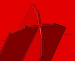
4-Way Locators:
These are the locators which arrest the 4 degrees of freedom by four ribs junctioning together. These are of the following type especially used for mold designs.
Ribs:
Ribs are thin, wall-like features typically designed into the geometry of a part to add internal support to walls or other features like bosses. In a similar fashion, gussets are support features that reinforce areas such as walls or bosses to the floor.
Ribs provide a means to economical stiffness and strength in molded parts without increasing overall wall thickness. They also facilitate:
Locating & arresting components of an assembly.
Providing alignment in mating parts.
Acting as stops or guides for mechanisms.
A well-designed rib will overcome the following disadvantages:
Increase part weight and cost proportional to the increase in thickness.
Increase molding cycle time required to cool the larger mass of material.
Increase the probability of sink marks.
Typical uses of Ribs:
Covers, cabinets and body components with long, wide surfaces that must have a good appearance with low weight.
Rollers and guides for paper handling, where the surface must be cylindrical.
Gear bodies, where the design calls for wide bearing surfaces on the center shaft and on the gear teeth.
Frames and supports.
Ribs design involves 5 main issues:
- Thickness.
- Height.
- Location.
- Quantity.
- Manufacturability.
Rib Geometry:
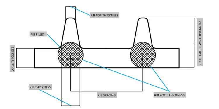
1)Rib Thickness:
Ribs should be designed to be 50-60 percent of the nominal wall thickness. Thinner does not provide much structure and may be hard to fill. Thicker ribs are tempting, but they can begin to introduce sinks on the cosmetic surface.
Bottom Rib Thickness :( 0.3 to 0.6) * Wall Thickness
Note: Top Rib Thickness should be minimum of 0.75mm.
2)Rib height:
For maximum effectiveness, rib height should be no more than three times the nominal wall thickness. Since the rib will be thinner than the wall, it may be hard to fill it if it is taller.
Rib Height= (3 to 5) * Wall Thickness.
3)Rib spacing:
Increase the number of ribs rather than their height in order to increase stiffness. Ribs should be spaced a minimum of two times the nominal wall thickness apart from one another.
Rib Height/Rib width ratio = 3:1 –steel.
Rib Height/Rib width ratio = 2:1 –preferred
4)Rib draft:
A minimum 0.5-degree draft will ensure that they release from the tool during molding.
Rib draft = (0.5 to 1) degree.
5)Rib coring:
Core thick ribs from the back or below to create a blank area and thinner rib walls. This will help mitigate cosmetic sinks.
6)Rib fillet:
Fillet at feature intersections to increase rib strength.
Rib fillet = 0.125 * Wall Thickness.
7)Rib Root Thickness:
It is the thickness at the intersection of the Rib and Wall of the plastic component.
Rib Root Thickness = (0.3 to 0.5) * Wall Thickness
Wall Thickness:
Maintain a wall thickness of less than 5 mm because thick walls can lead to long cycle times and poor mechanical properties.
Avoid large variations in wall thicknesses in order to simplify flow pattern and minimize variations in shrinkage that can lead to warpage.
Avoid abrupt changes in wall thickness, as this can create stress concentration areas that may reduce a part’s impact strength. Wall thickness changes should have transition zones that reduce the possibility of stress concentrations, sinks, voids, and warp.
Avoid gating near an area with a large variation in wall thickness because hesitation and race tracking can create non-uniform flow and shrinkage.
Heat Staking:
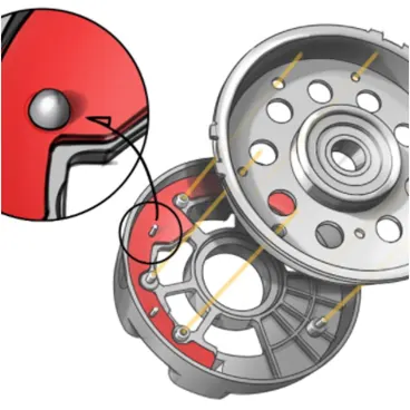
Heat Staking is a pulsed-heat process to join two or more parts out of which one at least is made of plastic. The process is to deform the plastic material using heat and force at a set process time. The bond is made by partially de-forming the plastic part in order to fix the other.
Heat Staking makes it easy to bond metal to plastic and is commonly used in high volume/low cost applications such as automotive, IT and consumer appliances.
Heat Staking Benefits:
Similar and dissimilar materials may be joined: metal to metal, plastic to plastic, metal to plastic
Accurate control operating within a small process window
Local heating resulting in no damage to surrounding materials
Processing of glass-filled materials
No mechanical vibration
Many heat-stake shapes are possible through custom designed tools.
Materials best suited for Heat staking:
Heat staking technology is ideal for most native and blended thermoplastics on the market today, as well as the most robust glass and/or other-filled plastics. It produces high quality results when used with any of the following materials:
- Polycarbonate (PC)
- Polypropylene (PP)
- Polystyrene (PS)
- Acrylonitrile butadiene styrene (ABS)
- Nylons (GFN or Nylon 6/6)
- Ultem (GFN or Nylon6/6)
This makes heat staking ideal for heat staking LED Stamped Arrays or LED Flex Circuits into the plastic housings for OEM automotive and aerospace industries. Heat staking is also the preferred process in many medical device assembly applications for attaching adhesive patches to wearable glucose monitor devices and wearable medicine dispense devices versus the more brittle feel of an ultrasonic welded patch against the patient’s skin. The ability to also easily transition to multiple assemblies per machine cycle makes heat staking a very desirable and controlled production equipment option versus other technologies.
When looking for heat staking plastic assembly machines and tooling, be wary of very inexpensive options – cheap or “low-cost” machines cannot be expected to maintain their temperature and motion consistently throughout the entire production run. Heat staking machines need to operate at a precise temperature, motion and force to ensure the “sweet spot” is maintained for optimum heat staking results, which occur below the thermoplastics melt temperature to maintain the most effective and repeatable assembly process.
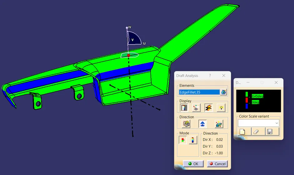
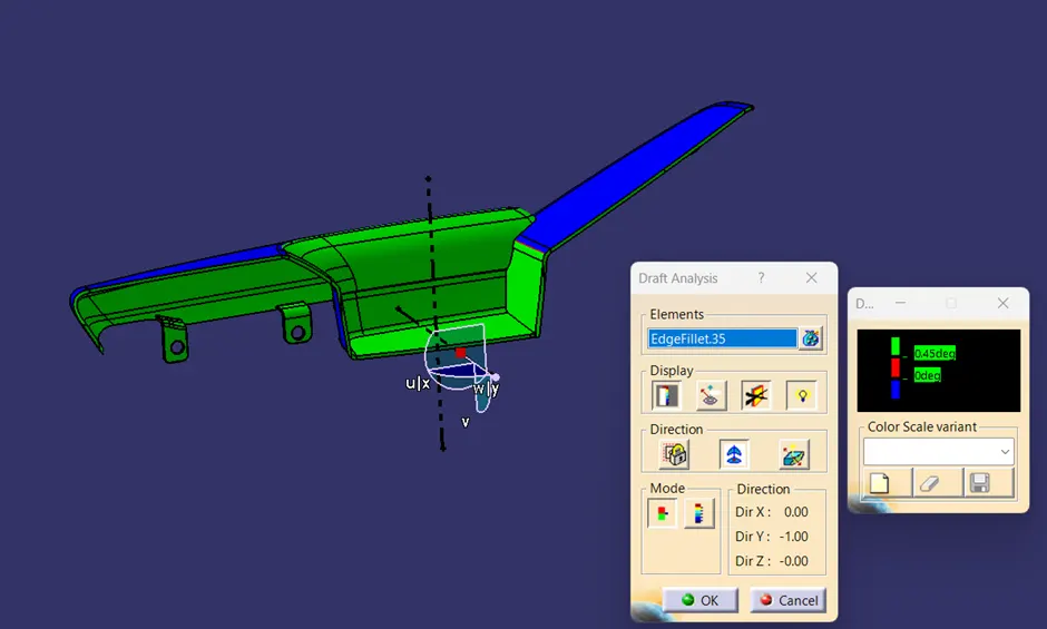
Draft Analysis:
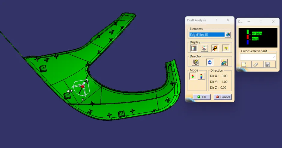
The draft analysis command enables you to detect if the part you drafted will be easily removed. This type of analysis is performed based on colour ranges identifying zones on the analysed element where the deviation from the draft direction at any point, corresponds to specified values.
The maximal draft analysis accuracy is 0.01 deg. According to the graphic card performance, this accuracy can be debased.
The different mapping analyses of the same surfaces cannot be displayed simultaneously, even if you have set the mapping analyses in no show. You need to visualize them one after the other.
Sequence of Operations to generate CAD Model of a plastic component:
- Extracting the input Class-A surface into different parts of Assembly.
- Looking for defects in Class-A surface.
- Improving Class-A surface by patching defects.
- Improving Class-A surface as per Master section.
- Creating Tooling Axis.
- Creating Class-B surface.
- Creating Class-C surface.
- Creating a Closed Body.
- Creating Dog House as per Master Section and OEM standard design Rules.
- Creating Locator as per Master Section.
- Creating Ribs as per requirement.
- Draft Analysis.
- Adding Draft as per requirement.
- Creating Side core Tooling Axis.
DESIGNING OF PLASTIC COMPONENT FOR GIVEN DOOR TRIM PANEL CLASS-A SURFACE:
Door Trim Panel consists of following Components.:
- · Door Arm-Rest.
- · Upper Map Pocket.
- · Lower Map Pocket.
- · Lower Substrate.
- · Upper Substrate.
- · Flanges.
- · Heat stakes and Dog Houses.
Extracted Surfaces:
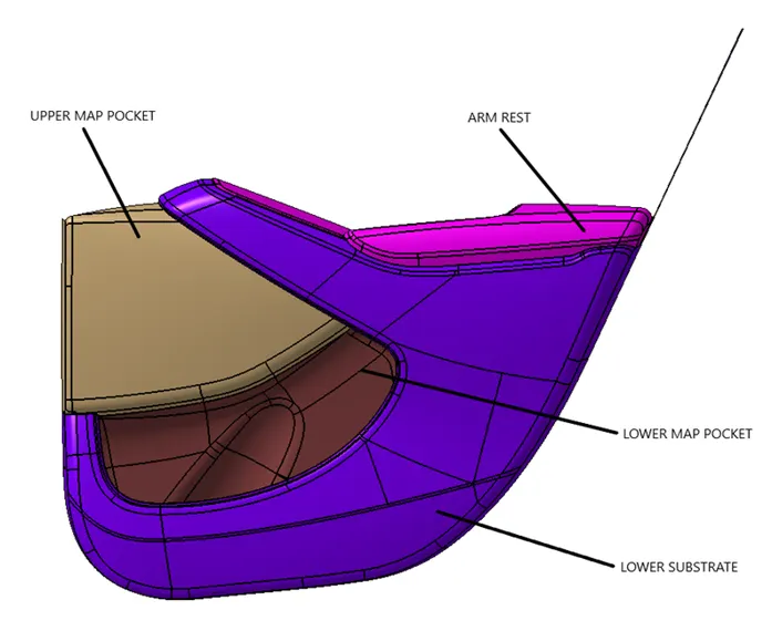
1.Door Arm Rest:
In the front of the car, a central armrest, which commonly folds away based on user preference, will also often include a storage compartment and sometimes even cup holders. Some also provide the location for controls for non-essential functions of the vehicle, such as climate control or window motors.
Extracted Class-A Surface:
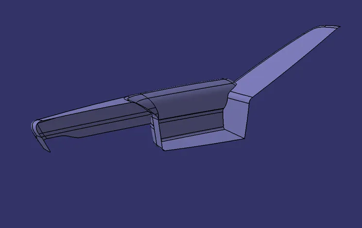
Creation of Tooling Axis for Arm-Rest
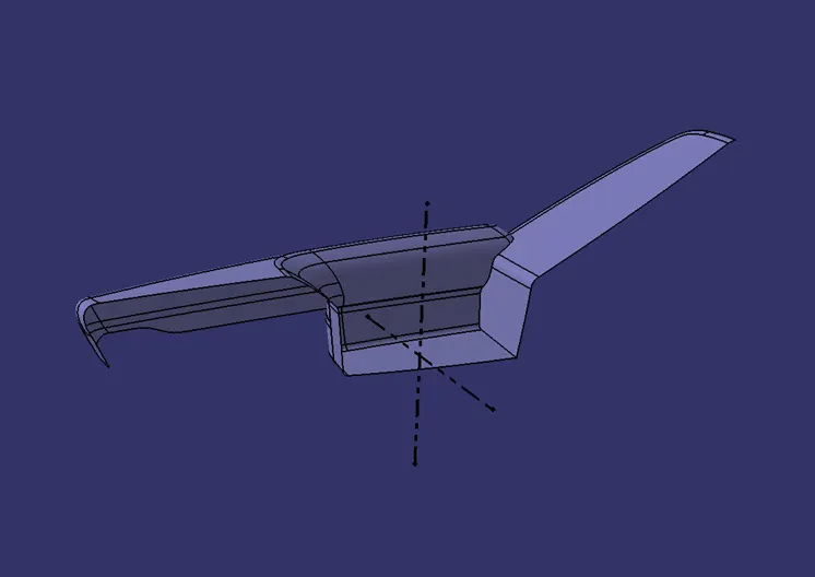
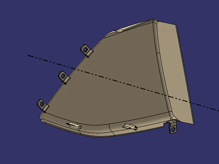
Creation of thickened plastic component with B-Side Features:
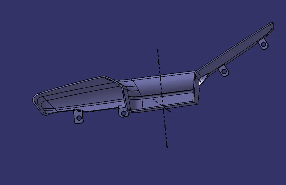
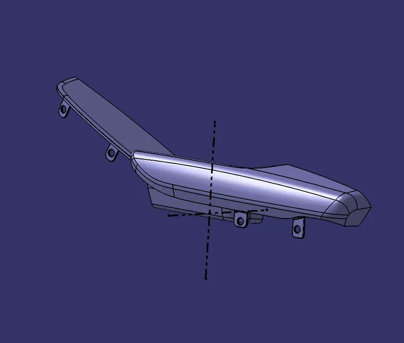
Draft Analysis of Arm Rest:
2.Map Pocket:
Map pockets can be created integrally within the door trim panel by forming a projection region outwardly towards the passenger compartment and then providing a separate panel attached to the rear outboard surface of the trim panel. This type of map pocket protrudes into the passenger compartment.
Another type of map pocket such as a recessed map pocket can also be formed within the door assembly such that the storage compartment of the map pocket is generally located between the trim panel and the outer metal panel of the vehicle door. An aperture in the door trim panel defines the opening into the map pocket. Generally, these types of map pockets are formed by a separate map pocket assembly which is fastened to the rear surface of the trim panel. The map pocket assembly includes a front portion and a separate rear portion which are connected together to form the map pocket assembly and define the storage compartment. The rear portion defines a rear wall of the map pocket assembly. The front portion defines a lower front wall and a pair of side walls. The region above the lower front wall is generally open to provide access to the storage compartment of the map pocket. The map pocket assembly is then attached to the rear surface of the door trim panel such that the opening of the map pocket is generally aligned with an opening formed in the door trim panel.
2.A.Extracted Map Pocket Class-A surface:
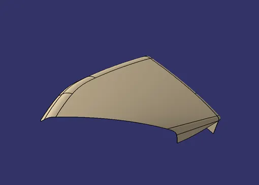
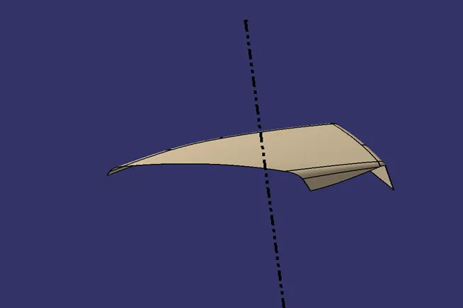
Creation of Tooling Axis for Map Pocket:
Creation of thickened plastic component with B-Side Features:
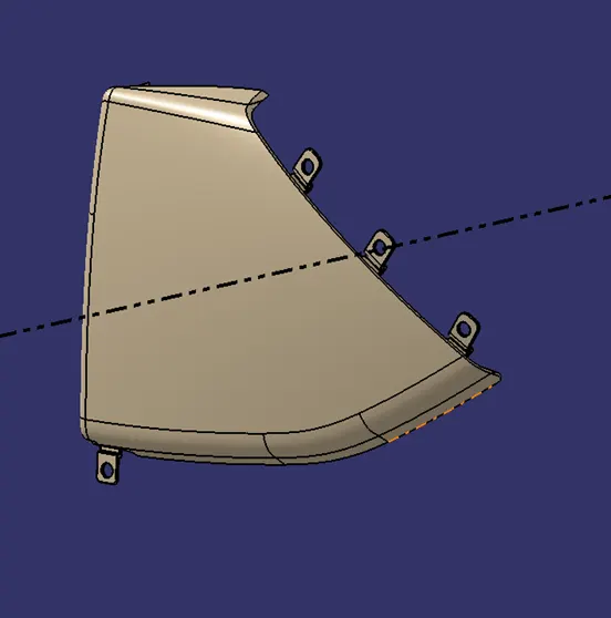
Draft Analysis of Map Pocket:
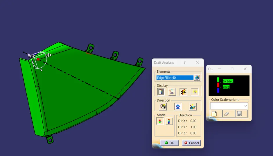
Extracted Bottle Holder Class-A Surface:

Creation of Tooling Axis for Bottle Holder:
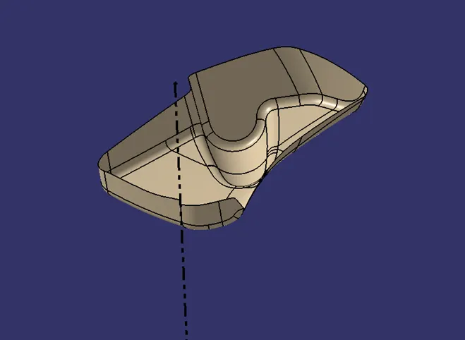
Creation of Thickened plastic component with B-Side Features:
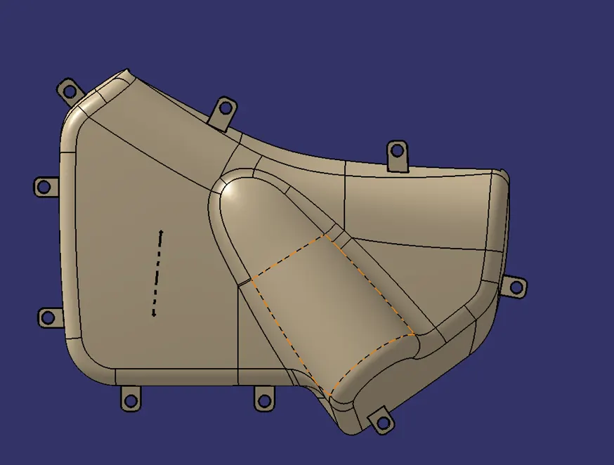
Draft Analysis of Bottle Holder:
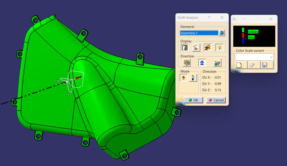
3.Extracted Lower Substrate Class-A surface:
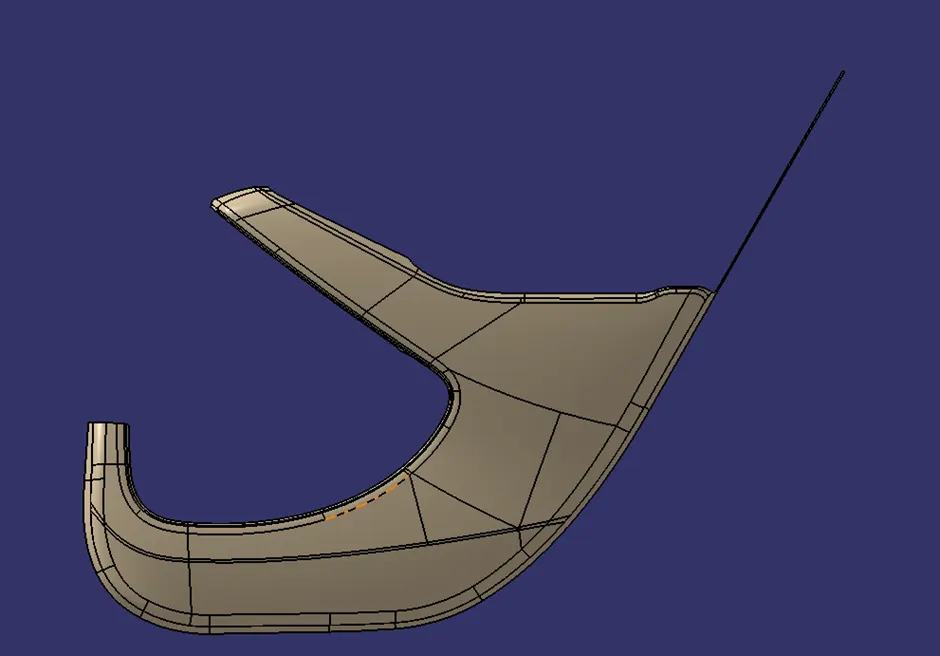
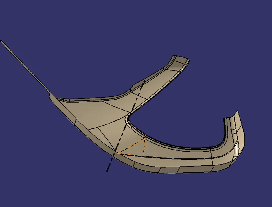
Creation of Tooling Axis for Lower Substrate:
Creation of Thickened Plastic component with B-Side Features:
Draft Analysis of Lower Substrate:
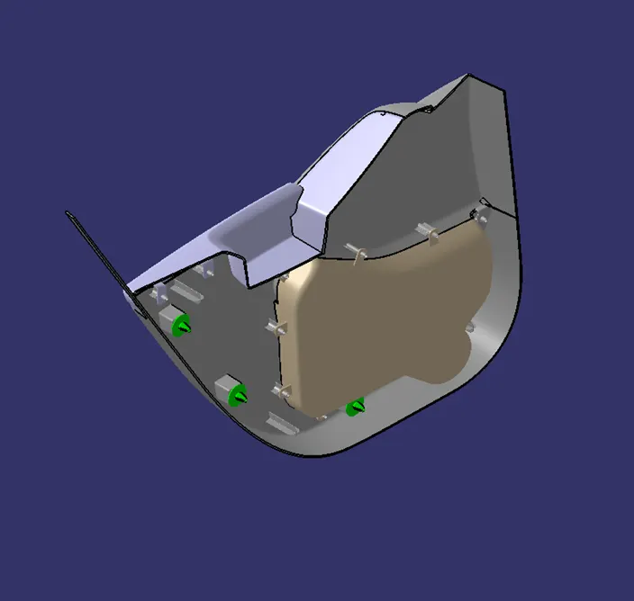
3.Design of Dog House and Push Pin:
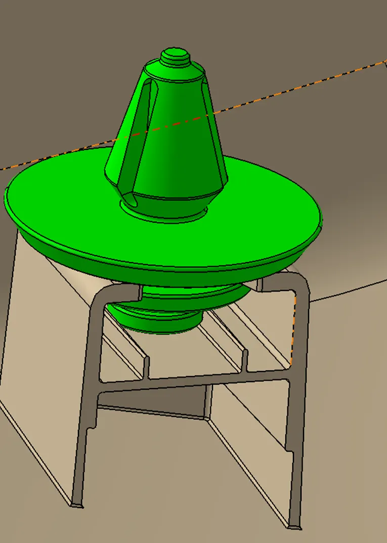
Images:
Isometric View
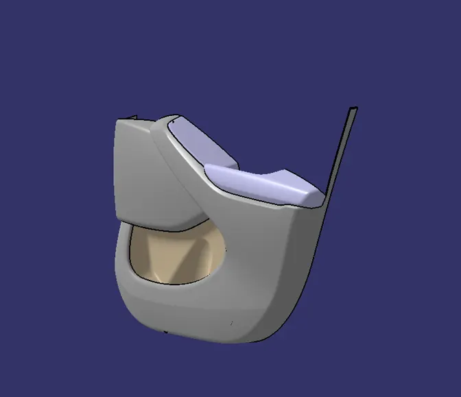
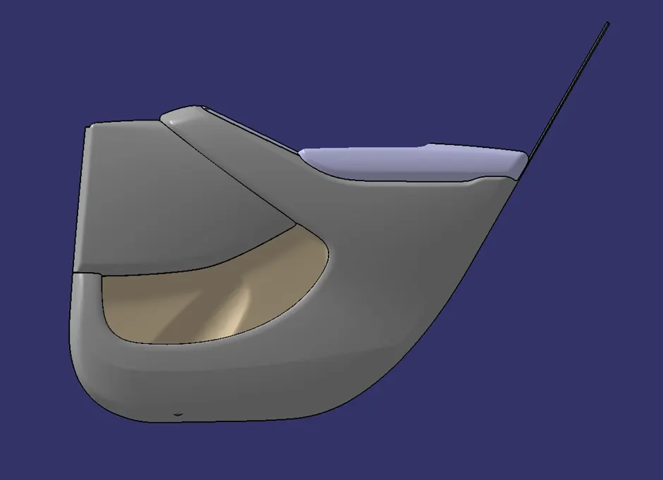
Y Direction

CONCLUSION:
Hence, Input surface is extracted into different components and B-side Features are created considering the OEM standards to design Plastic components.