Week 12- Final project
OBJECTIVE
To create a solid body of door plastic trim including Engineering features using CATIA v5 using given class A surface and master section and adding thickness to the component.
Procedure of CAD
This is stage where design engineers jump into design and development of new product and involved in this stages.
Designers will pass through given class A surface which came from the feasibility team.
A steps for creation of New product design are as below-
- Tooling Axis
- B surface creation
- C surface creation
- Closed body creation
- Draft Anaylis
Inputs given -
Interior door trim parts-
- Arm rest
- Lower substrate
- Map pocket
- Bottle Holder
Class A surface
In Automotive design , a Class A surface created by CAD industrial design applications and Alias . Class A surface can be improved whenever required by surface design commands .
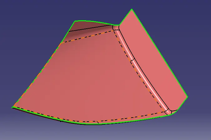
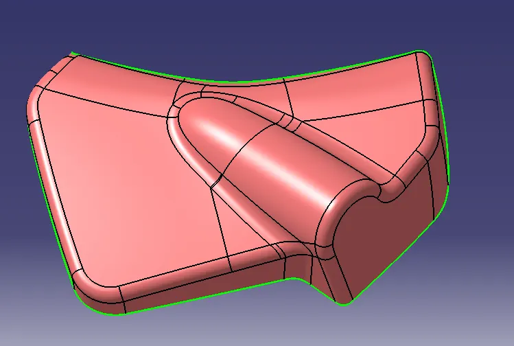
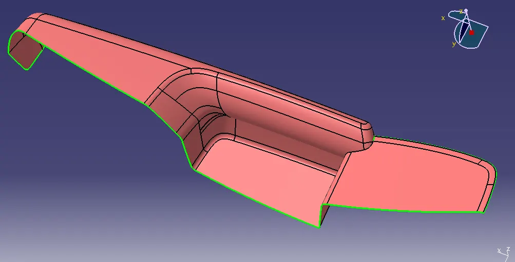
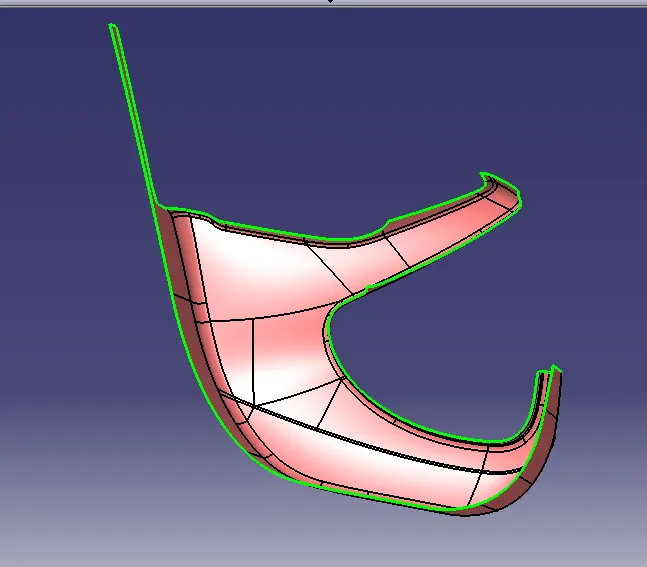
Tooling Axis
Tooling Axis is nothing but direction where core and cavity open and close. Design Engineers analyse class A surface and find out best possible tooling axis that component can be easily removed from the moulds.
Draft Analysis
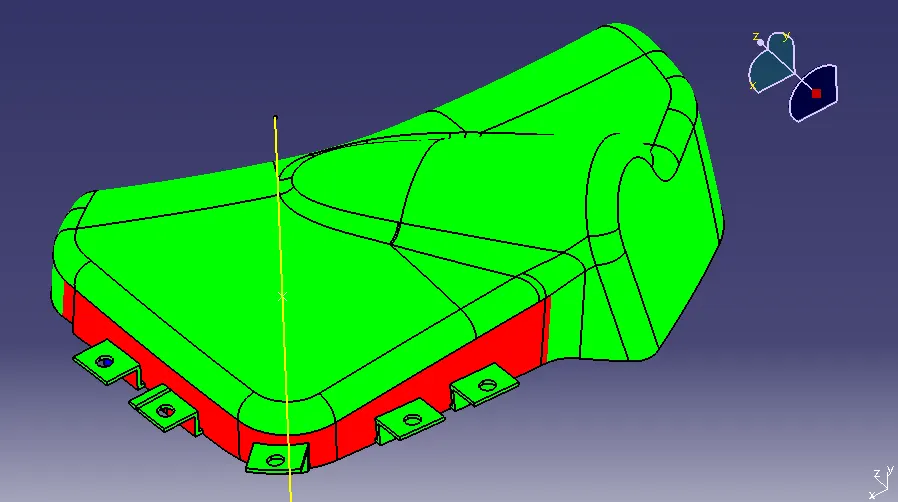
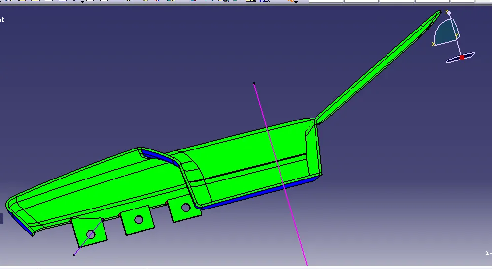
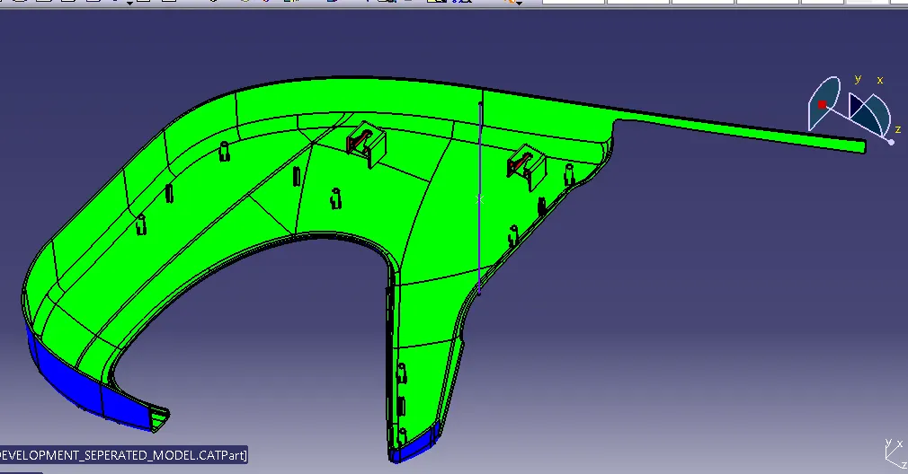
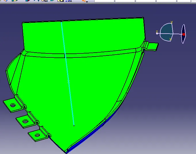
The Draft analysis enables you to detect if the part will removed easily from mould. This analysis based on color range identify zone on the analyzed elememt where deviation from the draft direction at any point , corrospond to spacify values.
Most of draft require minimum 0.5 degree to 1 dregree , however 3 degrees are widely accepted in plastic component design. Draft anaysis is a technique used to analysed whether our designed component meets Manufcturing criteria with required condition or not.
CLOSE SURFACES OF DOOER TRIM PANEL;
Class B surface creation -
- Class B surface includes derived surface created by offset surface from Class A surface to define thickness of material
- B surface creation which nothing but parallel with class A surface.
- B surface contains edges and fillets which Class A surface contains'
- For class B surface creation we need to disconuinity and work on offset surface by commands like - extract , multi surface solid , trim , split and join etc. offset value is 2.5 mm downword direction of class A surface
Class C surface creation -
- Class C surface will be created with Class A surface by sweep operation which join class A and class B surface. Sweep can be done as pr requirement as reference to surface of referance to tooling axis and sweep angle and direction should be provided .
Final Trim-
- After finishing alll 3 surface join class A and class C surface together using join command .
- Extrapolate class B surface to make sure B surface intersect with join of class A and class B .
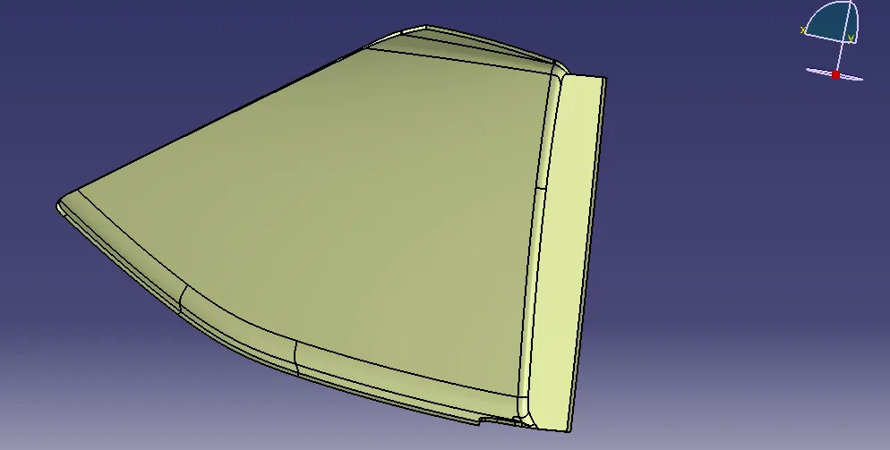
- Trim updated class B surface with join of class A and class C surface.
- Varify if there is any gape in surface .
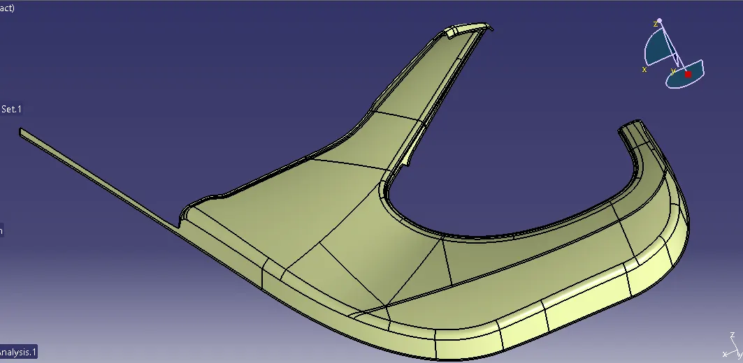
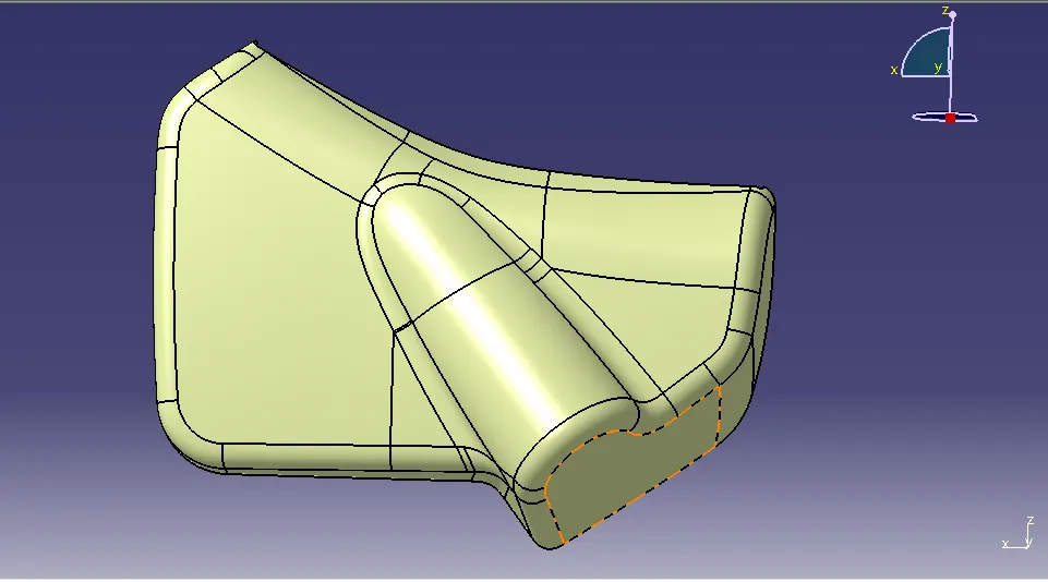
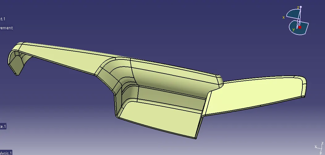
Make this surface to solid by closesurface command .
CREATION OF HEAT STATES , LOCATORS , FLANGES , DOG HOUSE
Dog House
- Dog house are created to avoid sink marks .
- Dog house wall thickness at intersection of the part wall 40% or less than main wall stock.
- Height should be between 3-6 mm.
- Dog House created on lower substrate.
Heat Stakes -
- Heat staking is a pulsed heat process to join two or more part in which one part at least is made of plastic.
- All Heat stakes will designed on lower substrate.
Locators-
- As per name its locating element as per 3-2-1 principle Component will move desired direction on axis during manufucturing.
- Locaters are made on lower substrate surface of door trim.
Flanges -
- Flanges are made on master section given on Arm rest , Map pockate and Bottle holder . We have make self flanges on bottle holder .
- Create skatch of given master section and make into surface by sweep or extrude surface .
- Make this surface into solid by close surface.
SOLID SURFACES OF ALL BODY WITH ENGINEERING FEATURES
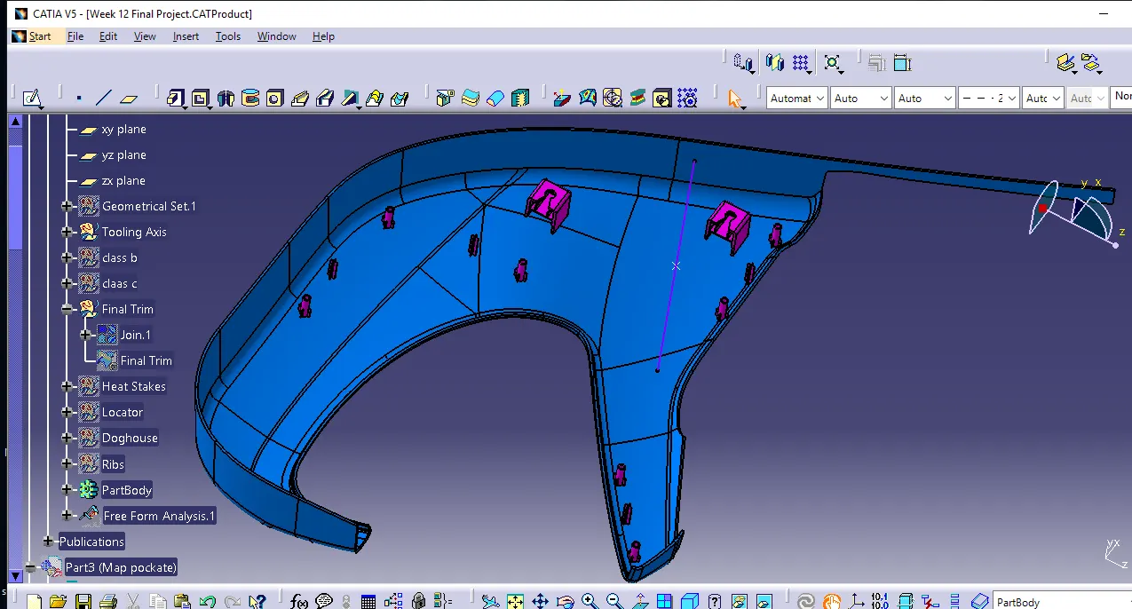
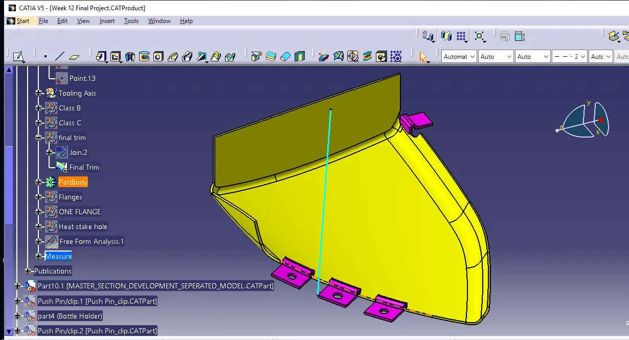
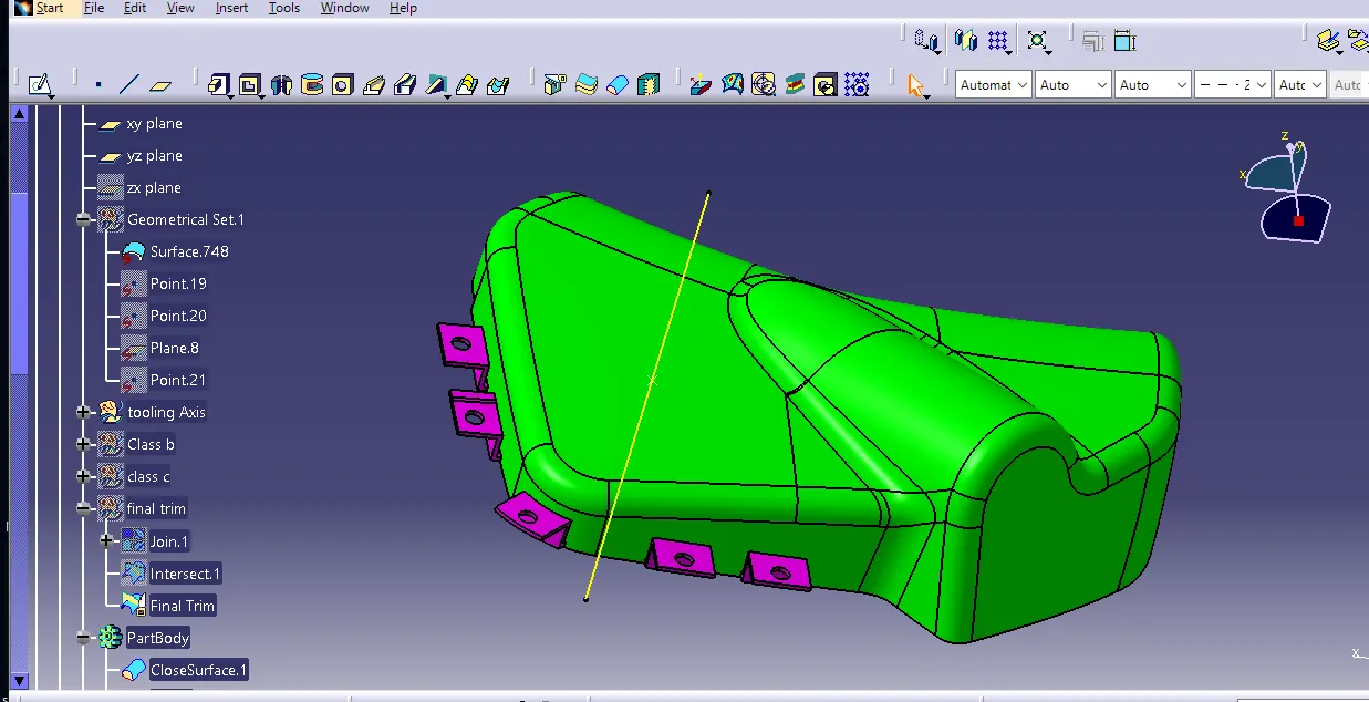
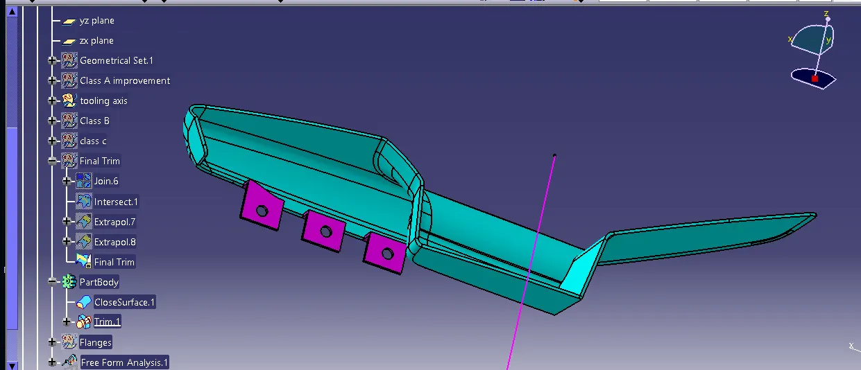
ATTACH GIVEN PUSH PIN IN PRODUCT FILE ON TOP OF DOG HOUSE HOLE.
PROVIDE PROPER DRAFT OF ALL ENGINEERING FEATURES . GIVE DRAFT VALUE OF 0.5 DEGREE.
ALL THIS ENGINEERING FEATURES WILL BE UNION TRIM WITH RESPECTIVE PART BODY .
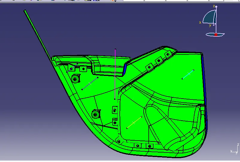
DRAFT ANAYLIS OF ALL COMPONENT
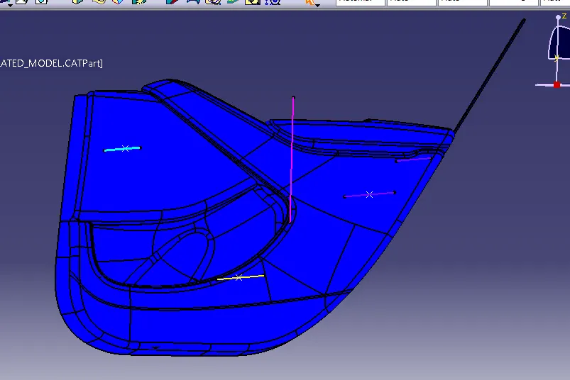
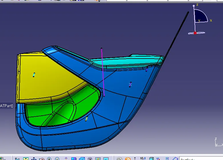
FINAL ASSEMBLY OF DOOR TRIM WITH ENGINEERING FEATURES
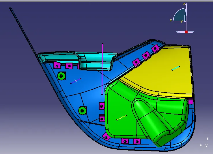
CONCLUSION
- Class A,B and C surfaces created as per automotive standerds using CATIA V5 software.
- Draft anaylis was performed for the built model and seen draft was under permissible limit and can be manufuctured as per automotive standards.
- Tooling axis given in bottle holder in Y direction .
- B side features were created for the component as per design rules.