Week 12- Final project
DEVELOPMENT OF A DOOR TRIM PANEL
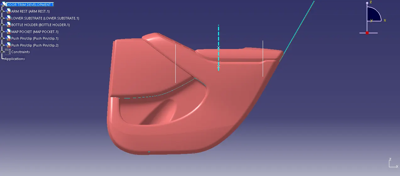
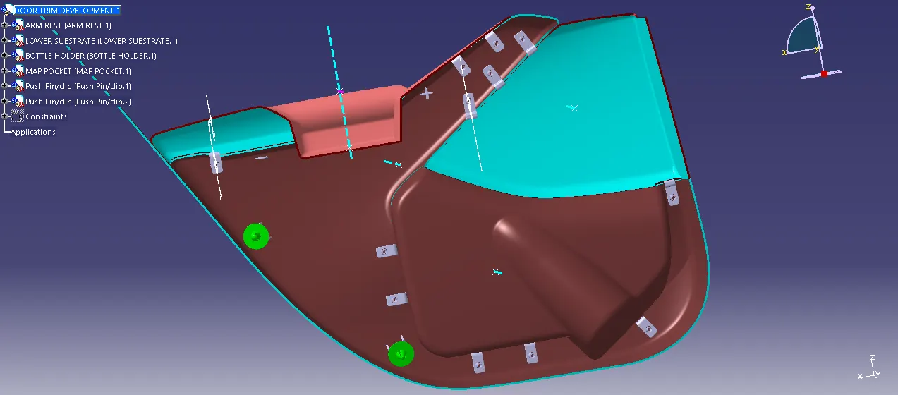
AIM: Creation of CAD model considering following inputs as like in OEM and tier1 companies
- a) Class A surface
- b) Nominal thickness: Refer to master sections
- c) Attachment strategy :
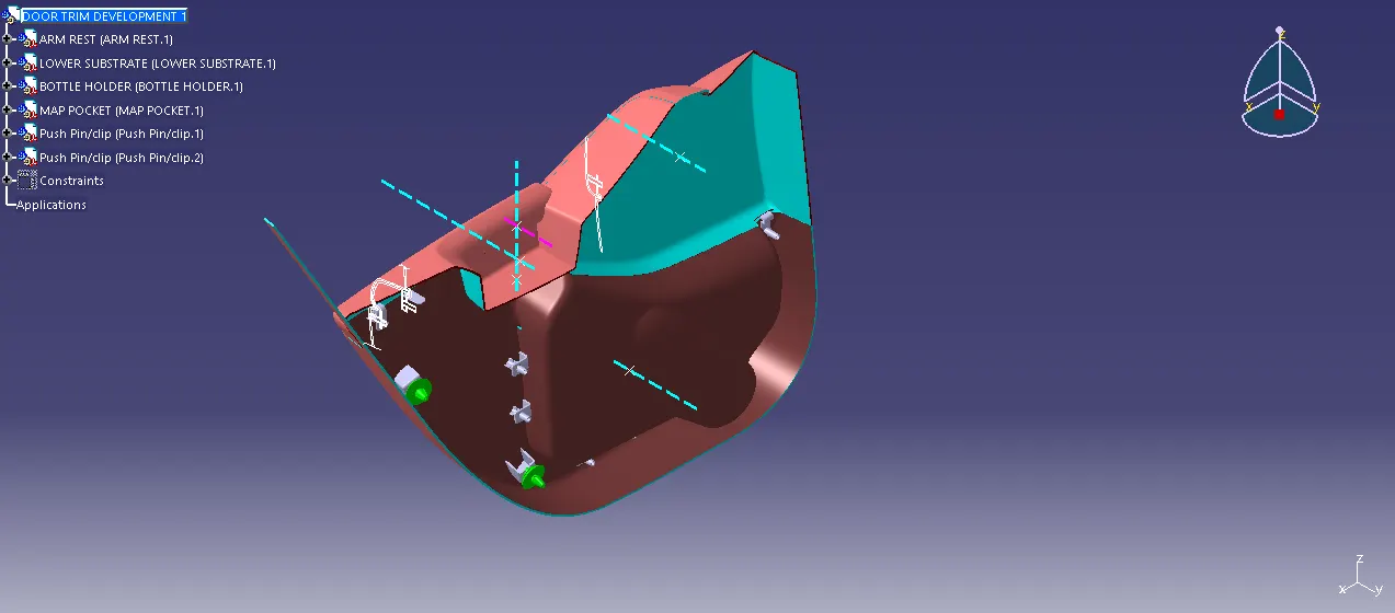
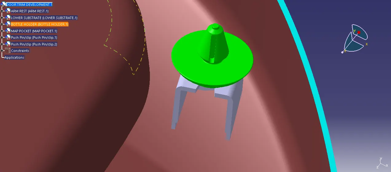
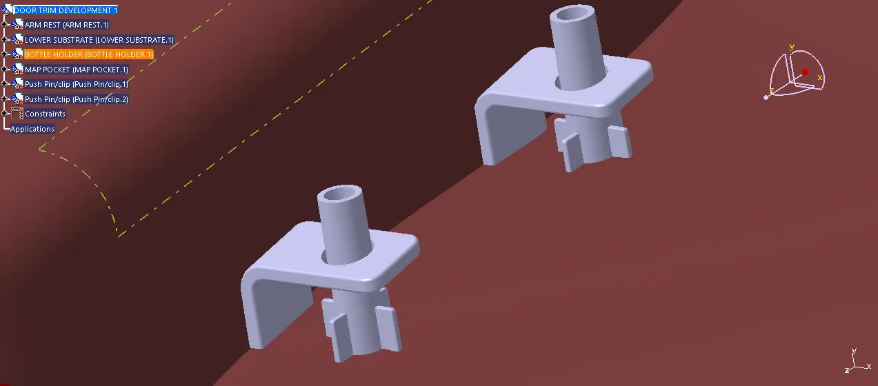
Use Pushpin with Dog house for Lower substrate – Door panel attachment
Use heat stakes for a part to the part attachment.
ABSTRACT:
The project report deals with the explanation of steps and procedure followed while developing the Door Trim Panel of a car using CATIA V5. Using the CLASS-A surface and master sections as input, we were able to create a Tooling axis, CLASS-B surface, CLASS-C surface, Flanges and form a solid body after which the attachment features such as Dog House, Push Pins, Heat stakes, etc are created. To check the manufacturability of the parts, a Draft Analysis has also been performed using the main/side tooling axis on various components such as
- Arm Rest
- Lower Substrate
- Map Pocket
- Bottle holder
- OUTPUT REQUIRED:
- CLASS-A surface extraction
- Creation of different Geometrical sets for each component such as lower substrate, map pocket (upper & lower part), armrest (upper & lower part), etc.
- Tooling Axis / Side Core Axis Creation
- Creation of Flanges
- Creation of CLASS-B Surface
- Creation of CLASS-C Surface
- Joining of CLASS-A, B & C Surface
- Performing a check for boundaries
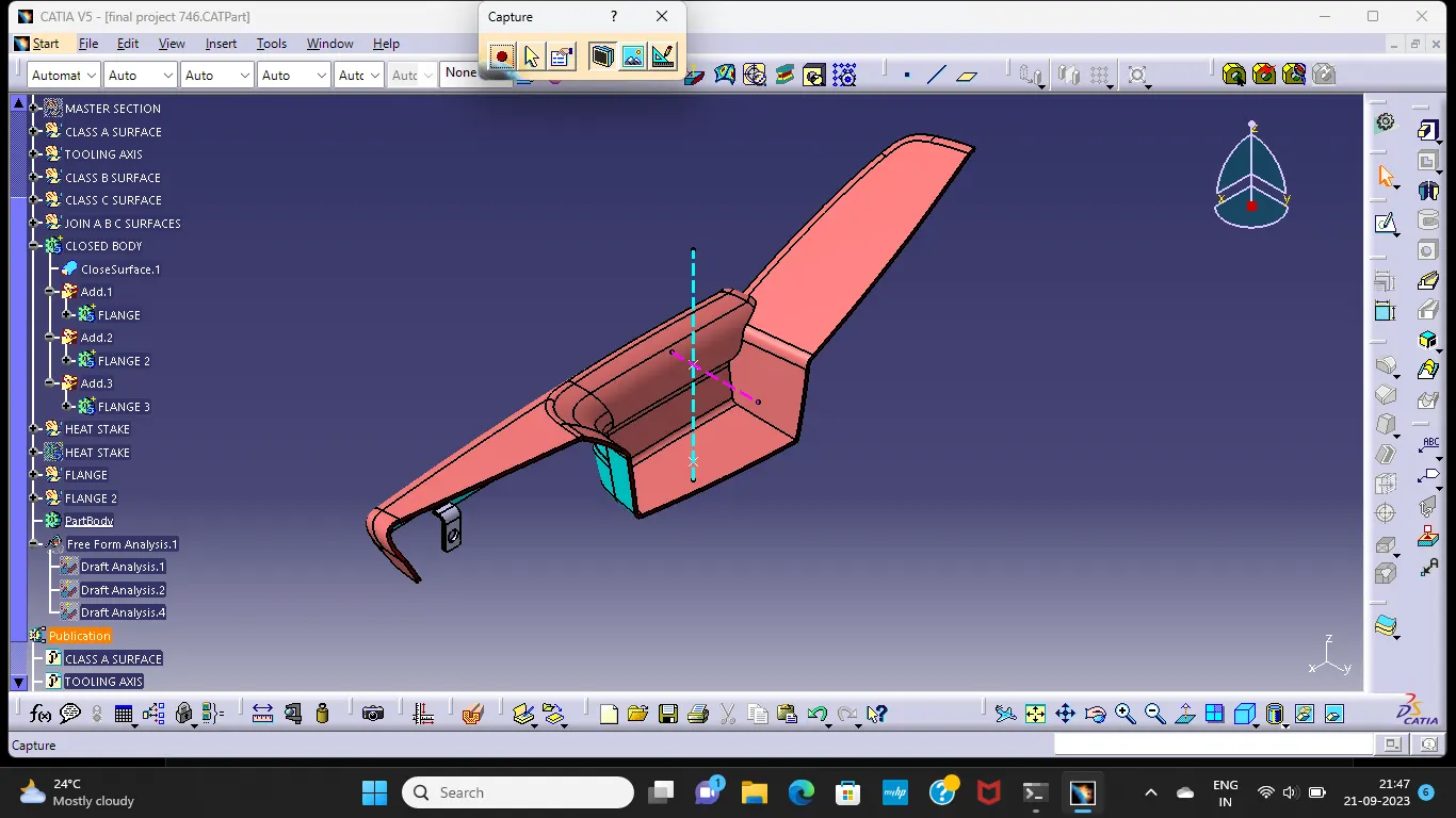
- Forming a Solid Body from closed surface
- Attachment features creation
- Performing Draft Analysis.
AUTOMOTIVE PLASTIC TRIM:
The design of Automotive Interior and Exterior plastic components is called Trims. The plastic components that you see inside the car are Interior. Ex: Dashboard, Instrument Panel, Doors, seating, and pillars. Plastic components that you see outside of a car are Exterior. ex: bumper, light assembly, hoods.
- PLASTIC PART:
When designing parts for injection molding,the manufacturing process is an important consideration. Injection molding is a process in which solid thermoplastic resin pellets are melted, injected into a mold, and then cooled back to a solid state in a new form. During both the injection and cooling stages of the manufacturing process, there are several factors that may affect the quality of the final product and the repeatability of the manufacturing process.
PROCEDURE:
CLASS A AND MASTER SECTION EXTRACTION:
The first step to follow in this project is to extract the CLASS-A surface (individually for each component) of the Door Trim Panel and divide these surfaces into different Geometrical sets as follows.
- Arm Rest
- Lower Substrate
- Map Pocket
- Bottle holder
We first check the given class A surface for any error in the surface elements. To do this we have to first extract the class A surface and then join it with the merging distance of 0.001 mm. This will show where the surface elements are weak. These weak sections have to be improved. The joined surface is then given as an input to the A-surface geometrical set.
CONSTRUCTION OF TOOLING AXIS:
TOOLING AXIS:
Tooling direction is basically the direction that mold pulls apart. The mold is built in two seperate pieces, basically you have a cavity side and you have core side, The core pulls apart from the cavity and that's the Tooling direction. While creating a Tooling direction make sure that waterver that is created that is going to be used as a reference to design it may also include Ribs, Pockets, Walls Bosses etc. All are going to be drafted with respect to Tooling axis to make sure that the core can pull apart from the cavity nice and clean.
PROCESS:
since the extracted class A are of complex geometry for Bisecting method to get the tooling axis ,even though we create it,it won't be accurate when we apply draft analysis on that tooling direction and also takes too much time and effort.so it is better if go with the trial method of moving compass until we get the satisfied analysis result to do that go to Insert > Analysis > Feature Draft Analysis and Simply place the compass on the largest flat surface then Check the Analysis by Tilting the Compass by Orientation or Rotation about an axis to get the desired result. After choosing the particular orientation,lock the compass direction.
now we have locked the definite direction of tooling axis now we will create a straight line which itself will be tooling axis.first we create a point on the surface before creating tooling axis.
CREATION OF B SURFACE:
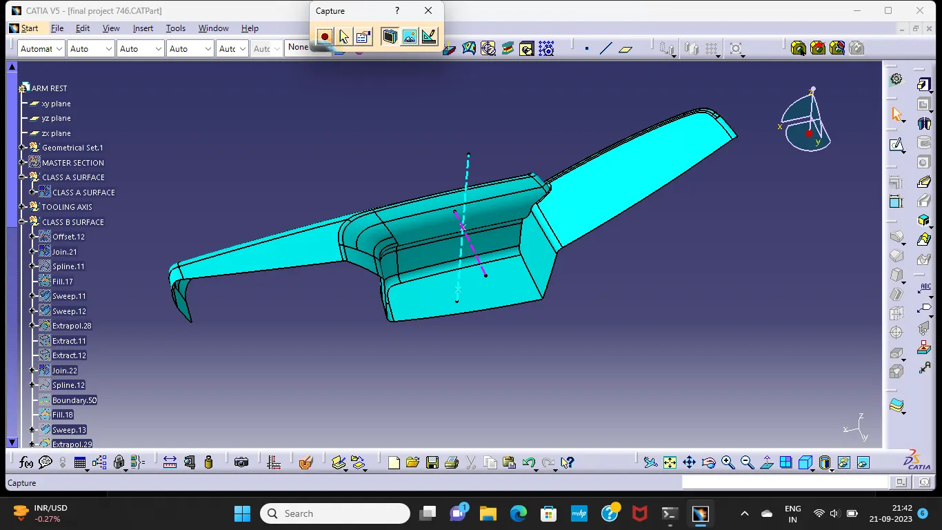
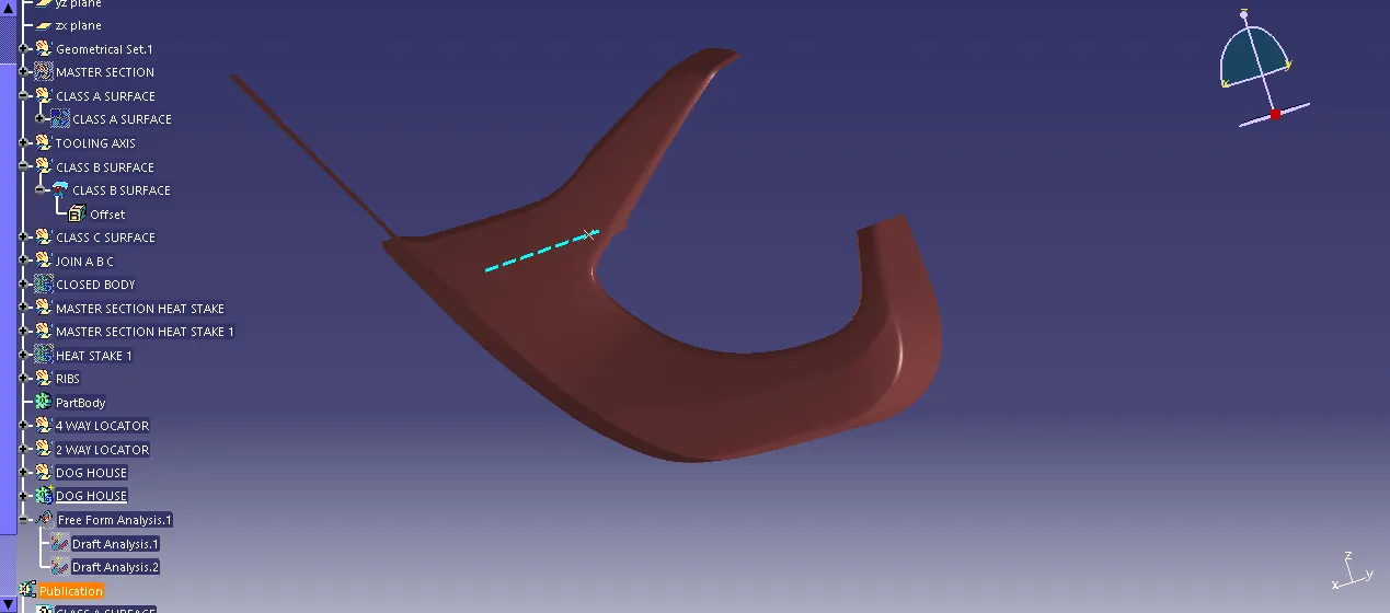
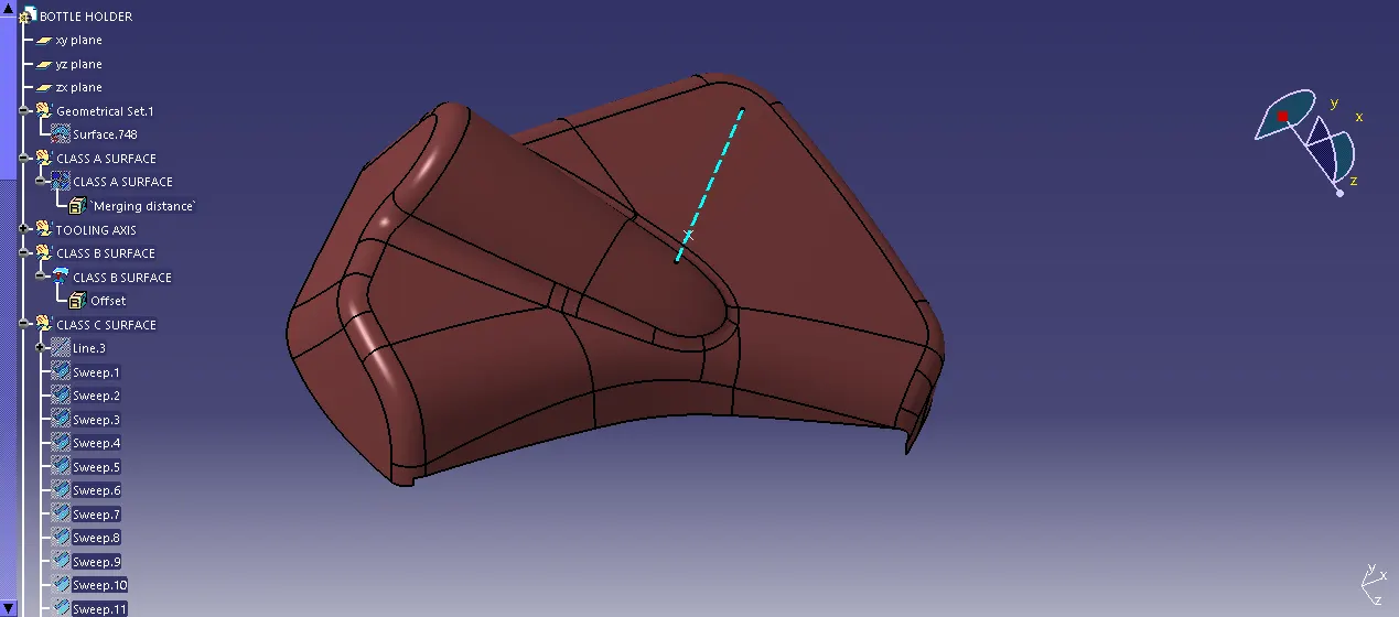
Class B surfaces are the secondary surfaces that you may see sometimes or may not, but are less important. These must be smooth and "error-free" as well, but are not held to the standards that class A surfaces are. After creating the Tooling axis, B surface is to be created which is nothing but the surface parellel to the A surface. B surface contain all the fillets and the edges which the A surface containsDepending on the geometry, the extraction and offset of the fillets might generate non-uniform thickness. So it is advisable to extract only the flat surfaces and then apply fillets at the end of Class B formation.
CREATION OF C SURFACE:
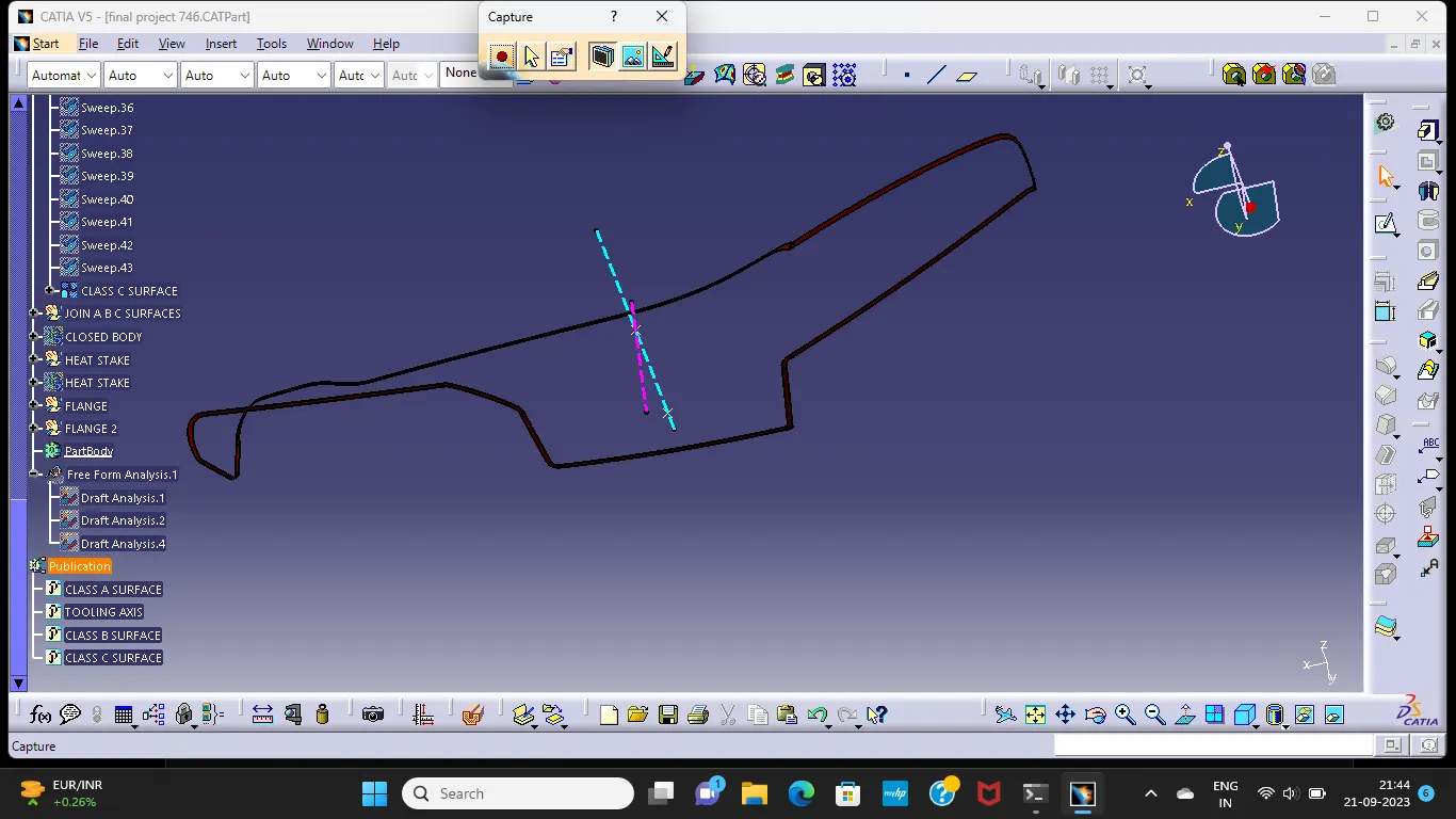
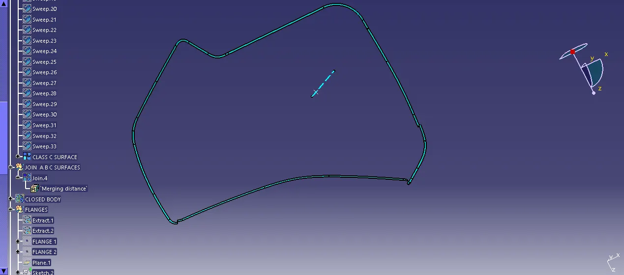
C surface is the part of the geometry that connects Class A with B surface.Rules to be followed for C surface creation is A minimum draft of 3 degrees should be provided to facilitate the Ejection of the Molded component.The parting line should be on the B surface. This means that the draft should sweep outwards, from the C surface.
FINAL DRAFT ANALYSIS:
In the injection molding process, plastic products are difficult to demold due to friction force between the cavity and products, thus, finished products might be deformed or damaged. Therefore, designers should add a draft angle to the geometric surface of products, which is parallel to the unloading direction, in order to help the products eject smoothly from the cavity. This study uses CAD software as the main architecture to develop the function of automatic draft angle recognition and construction. The study is divided into three stages. First, the geometric features of products are identified in the CAD model by induced algorithm, then the quilts to be added in the draft design are determined and classified. Finally, draft angles are created in different ways according to different surfaces
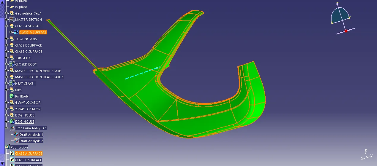
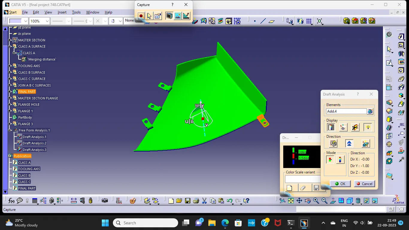
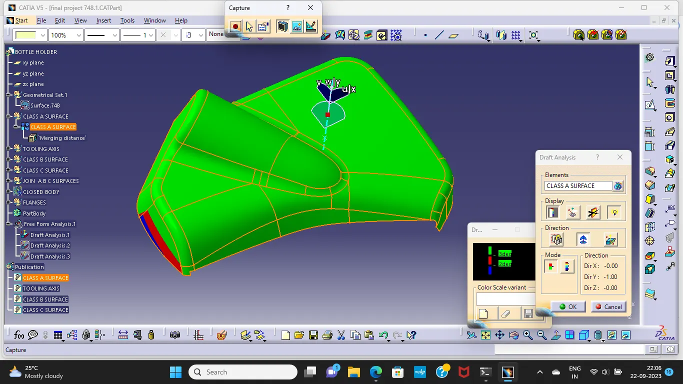
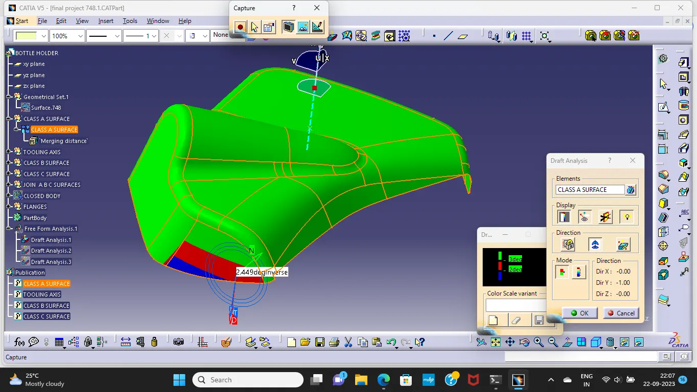
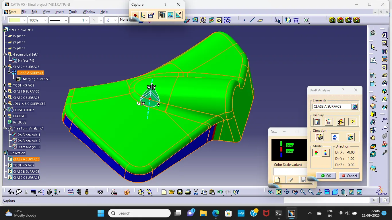
The draft analysis button within CATIA V5 will help you quickly gather the draft angle on multiple surfaces without the need for tedious manual measurements.we go to Insert > Analysis > Feature Draft Analysis.it will automatically enables a popup window to ensure you have the Material view mode ON.
once the material mode is selected Define the Draft direction using the "Compass" option then drag the Axis system representation close to the model and align it along the tooling axis to avoid the accidental movement of compass we will lock the Draft direction using lock compass option in the menu when we right click on the compass,set the Colour scale.
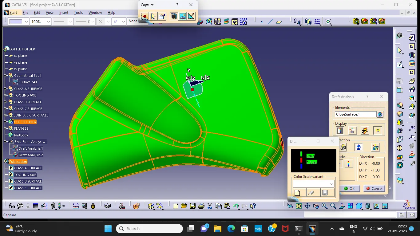
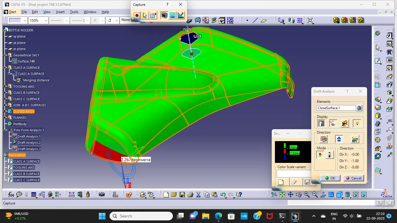
Place the Analysis Tool (Arrow Icon) anywhere on the model and review the colours on the feature.If any feature is showing Blue/Red then choose the same option again (It will switch to Analysis under Running point) and place it on the respective feature to review the deviation of the sweep angle from the Tooling Axis.
ARM REST
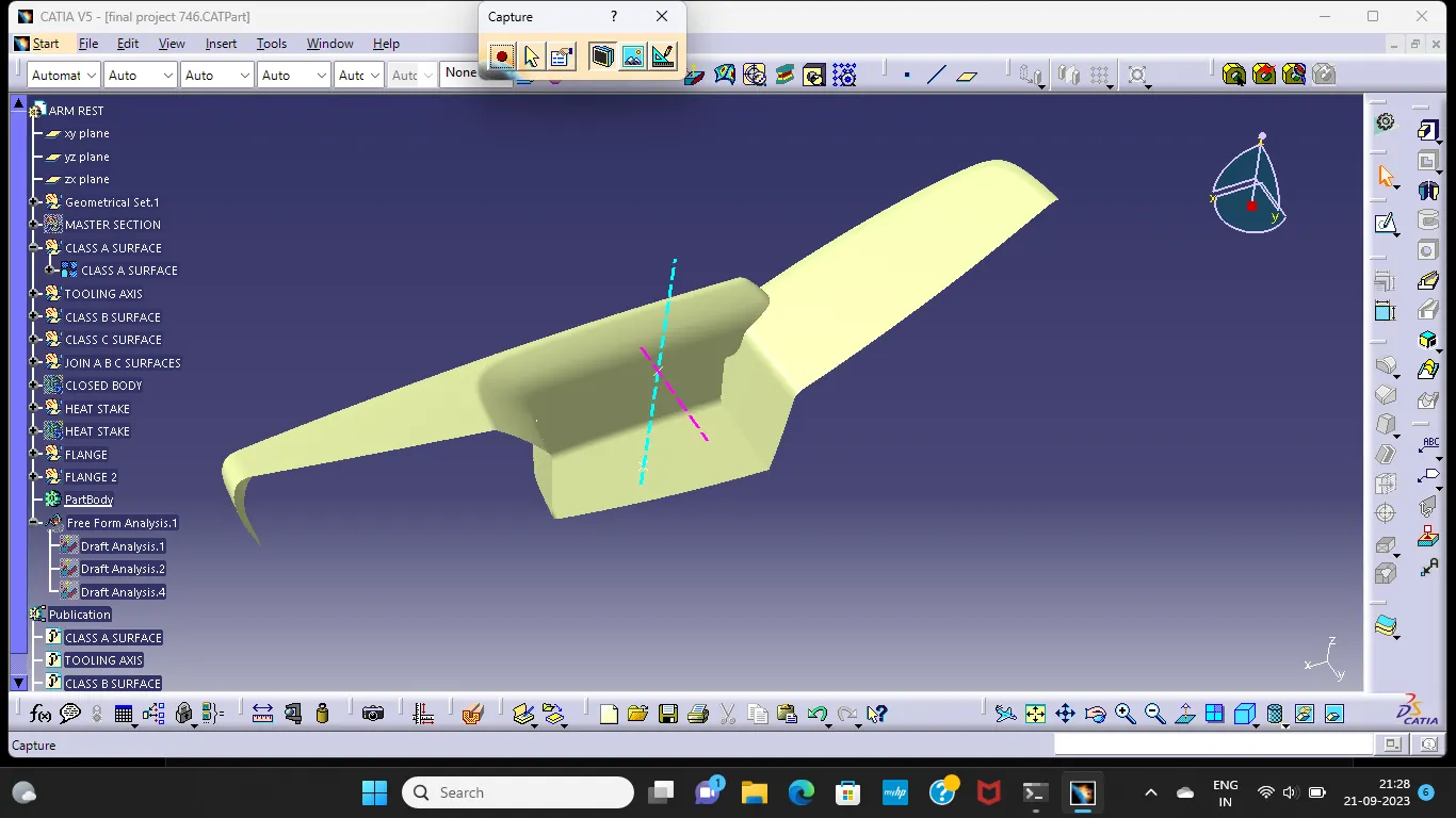
CLASS A SURFACE:
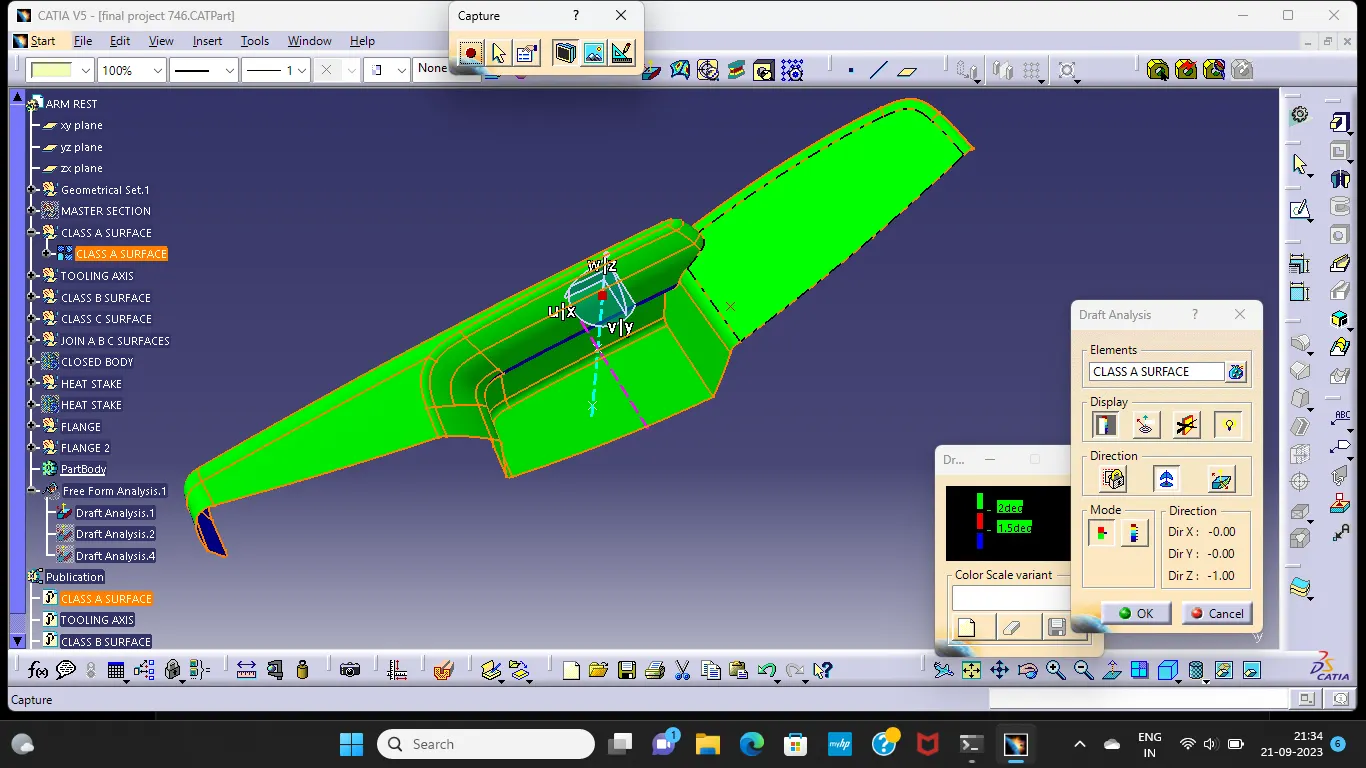
CLASS A DRAFT ANALYSIS:
MAIN TOOLING AXIS:
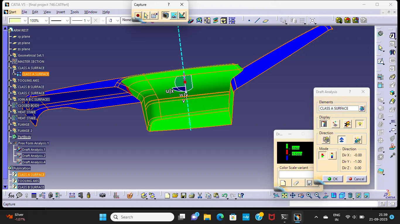
SIDE CORE AXIS:
CLASS B SURFACE:
CLASS C SURFACE:
CLOSED BODY:
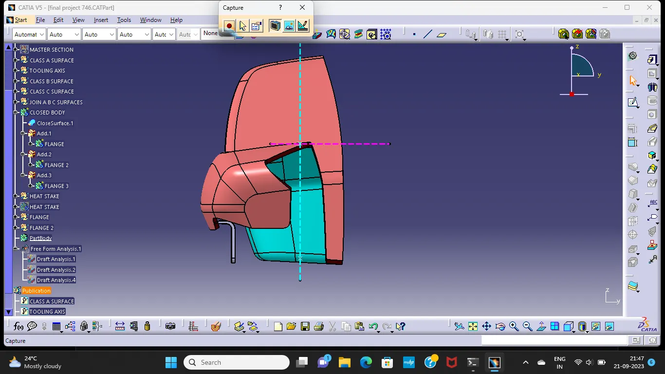
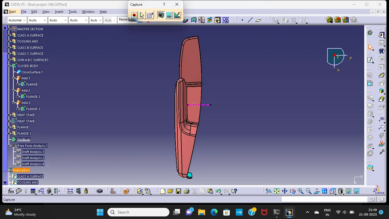
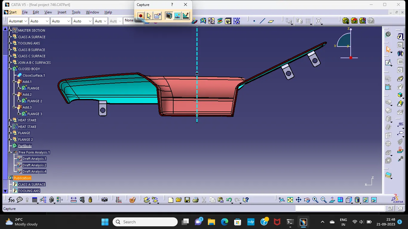
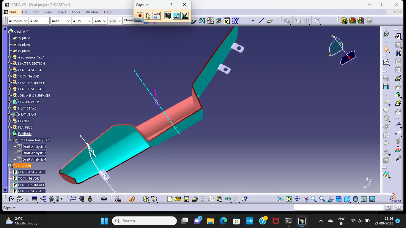
MASTER SECTION FLANGE:
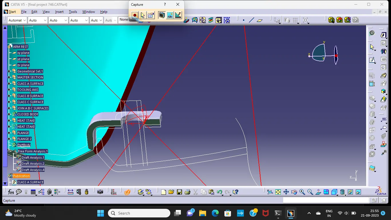
CLOSED BODY DRAFT ANALYSIS:
MAIN TOOLING AXIS:
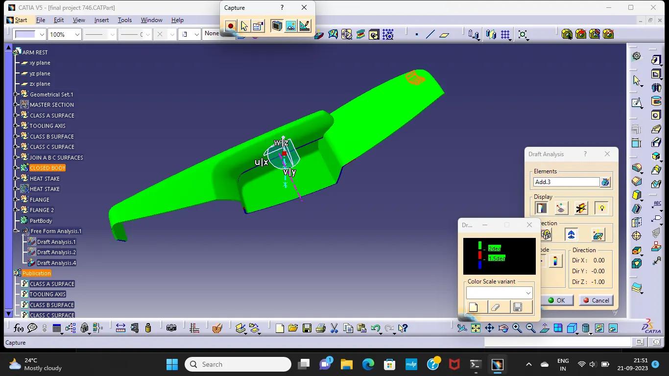
SIDE CORE AXIS:
2) LOWER SUBSTRATE:
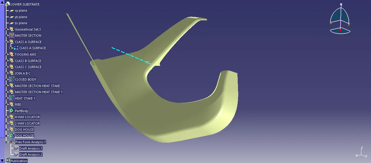
CLASS A SURFACE:
CLASS A DRAFT ANALYSIS:
CLASS B SURFACE:
CLASS C SURFACE:
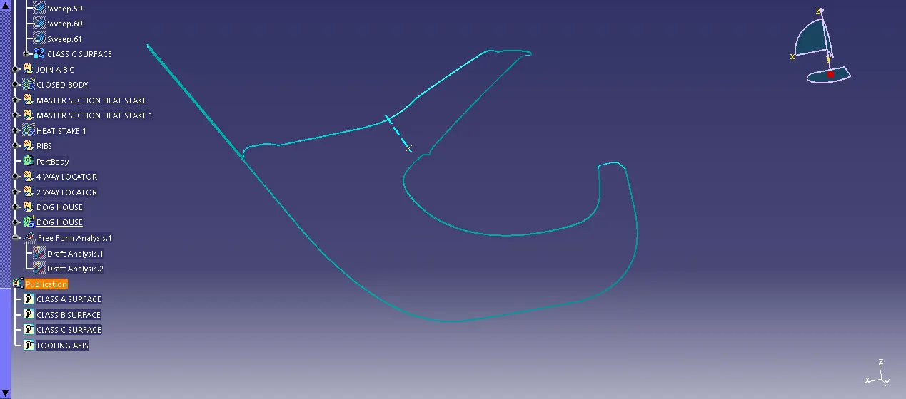
CLOSED BODY:
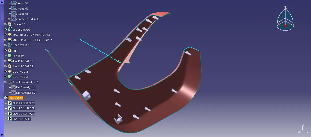
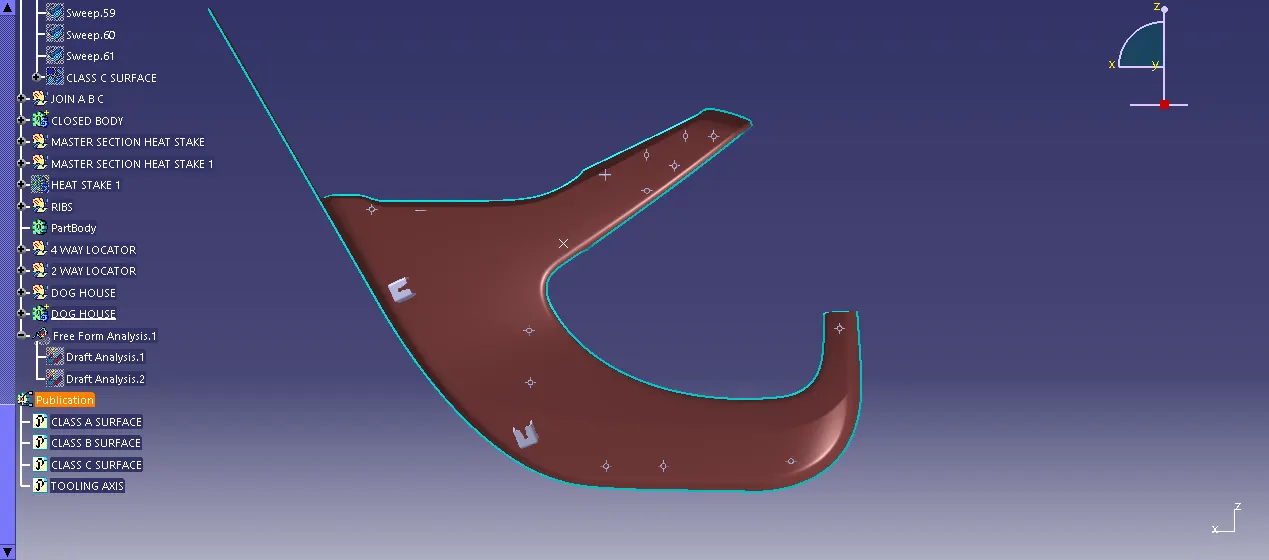
CLOSED BODY DRAFT ANALYSIS:
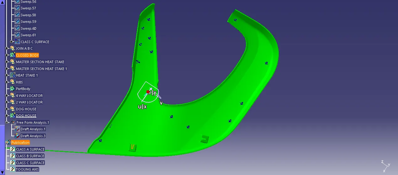
DOG HOUSE DRAFT ANALYSIS:
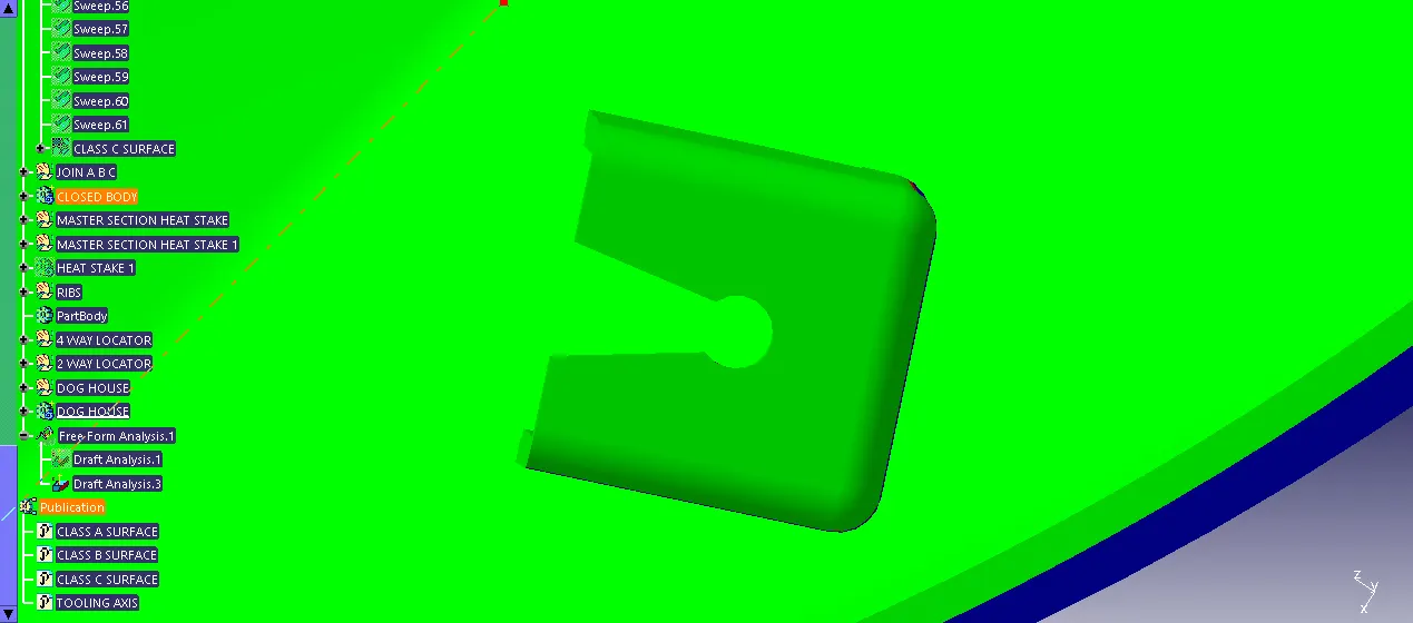
HEAT STAKE MASTER SECTION:
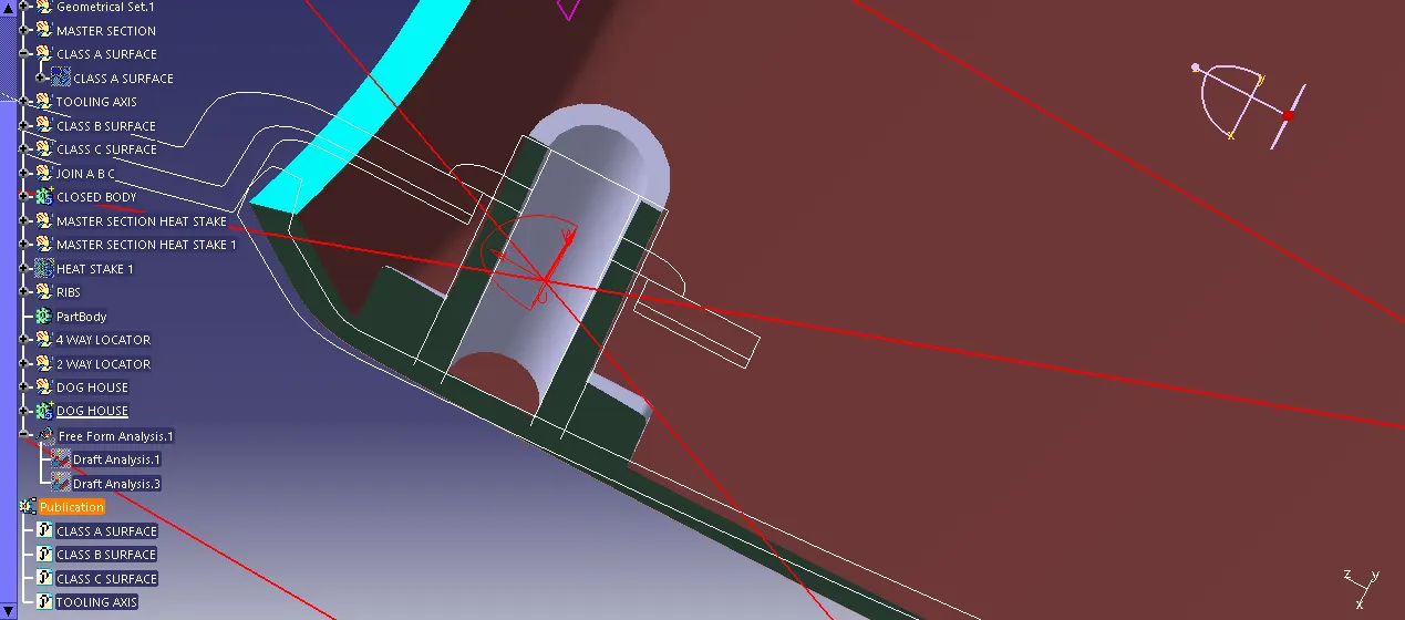
3) MAP POCKET:
CLASS A SURFACE:
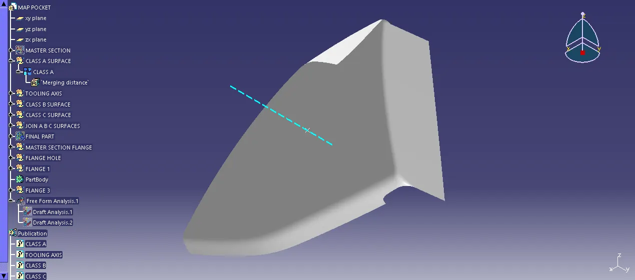
CLASS A DRAFT ANALYSIS:
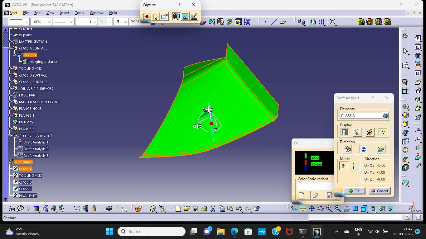
CLASS B SURFACE:
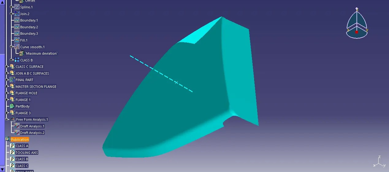
CLASS C SURFACE:
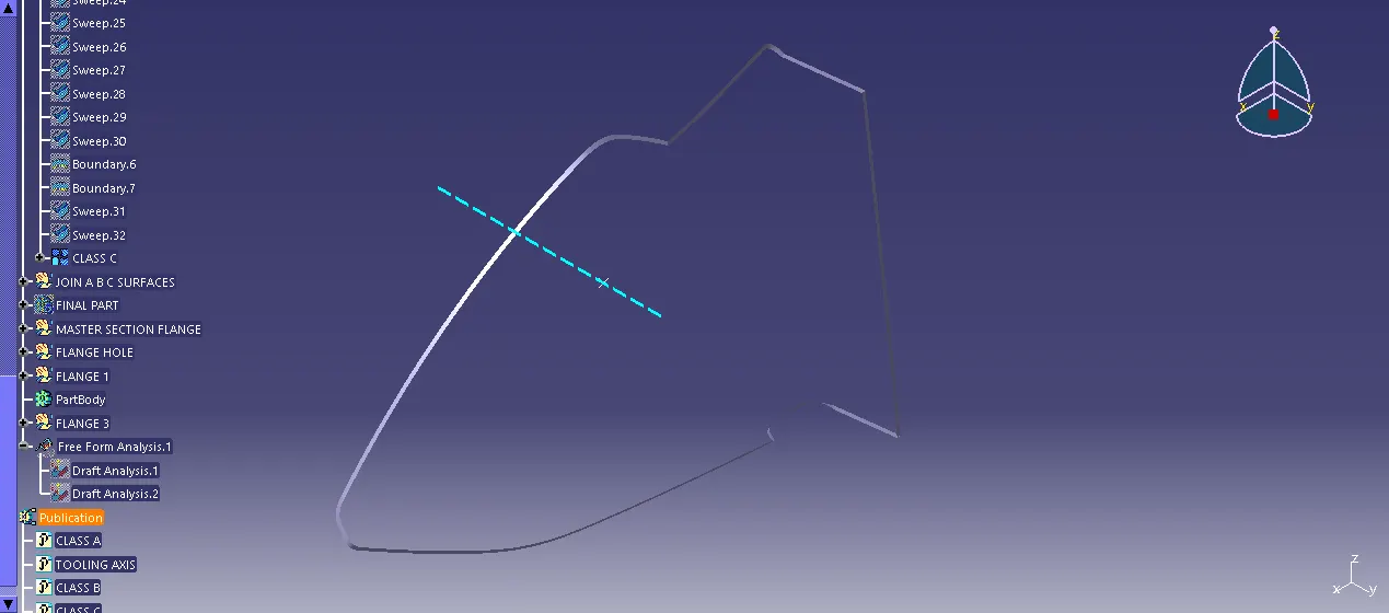
CLOSED BODY:
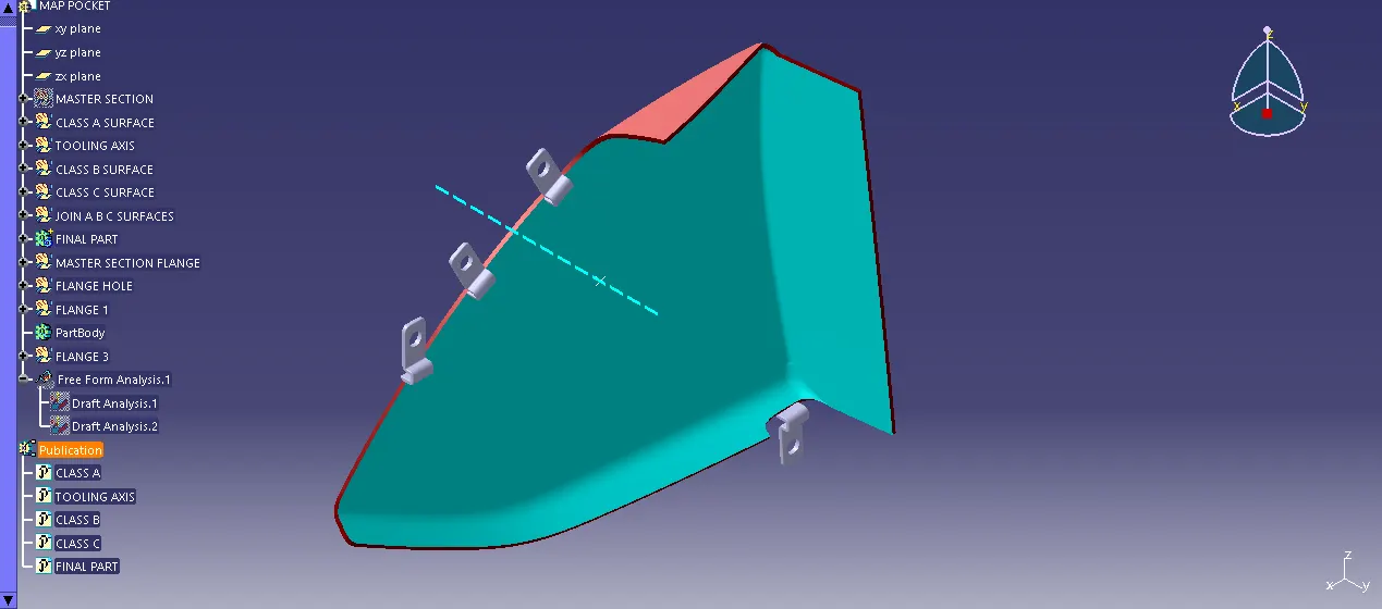
MASTER SECTION FLANGE:
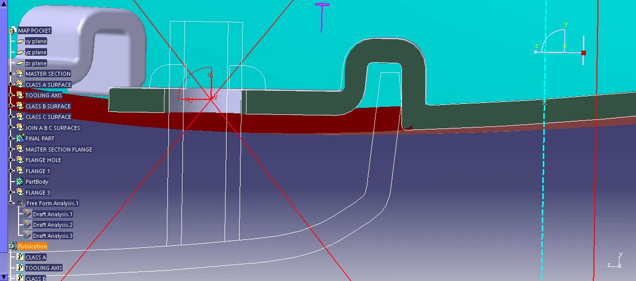
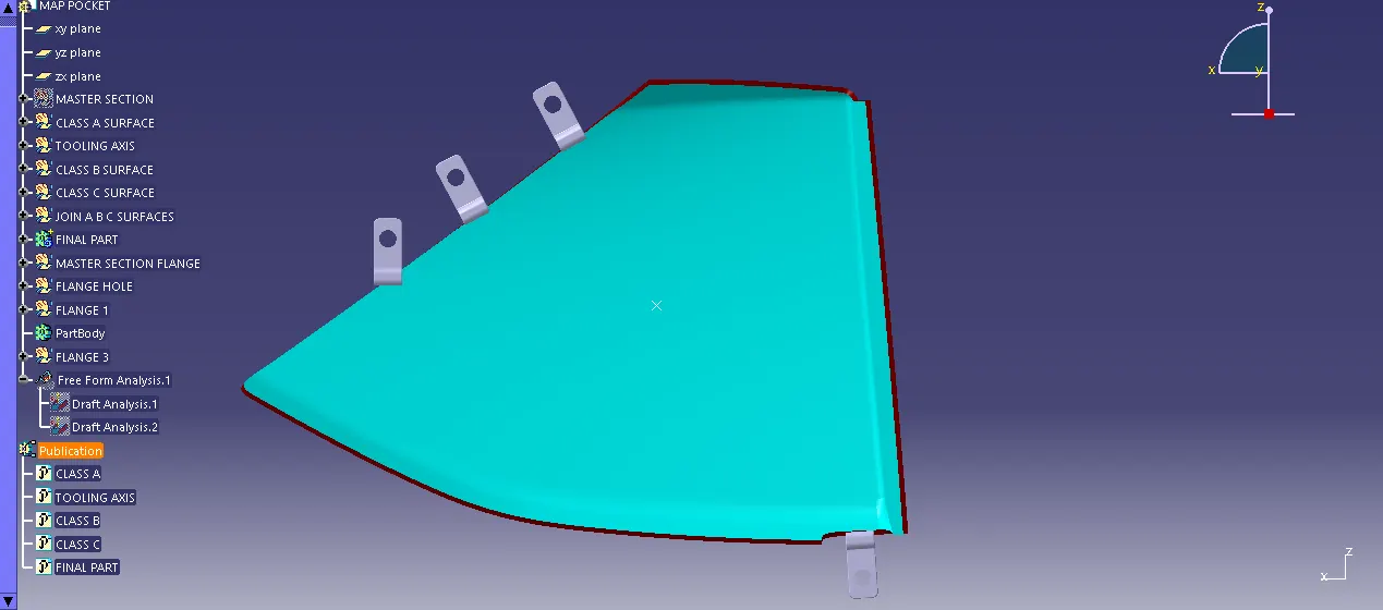
CLOSED BODY DRAFT ANALYSIS:
4) BOTTLE HOLDER:
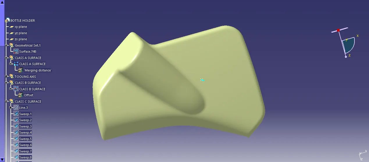
CLASS A SURFACE:
CLASS A DRAFT ANALYSIS:
CLASS B SURFACE:
CLASS C SURFACE:
CLOSED BODY:
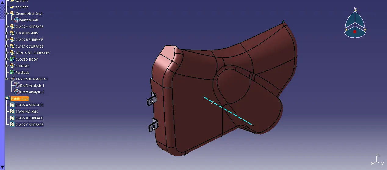
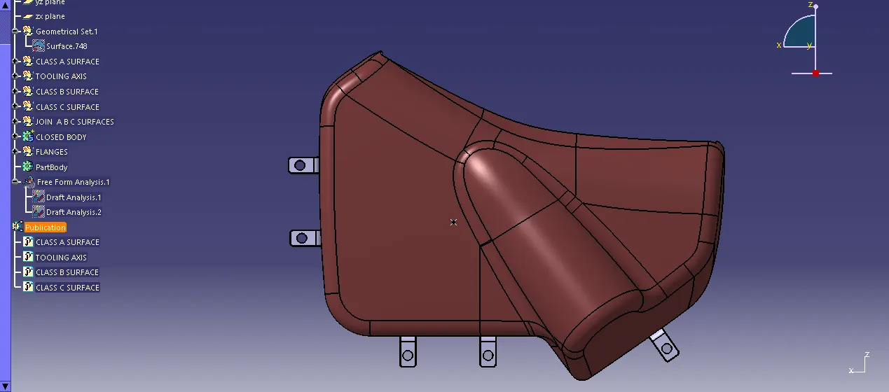
CLOSED BODY DRAFT ANALYSIS:
DEVELOPMENT OF A DOOR TRIM PANEL: