Week 12- Final project
Week 12- Final project
Development of a Door Trim panel
Aim:
To create a CAD model for door trim panel's parts by considering the given inputs of class A surface along with master section by following the design rules
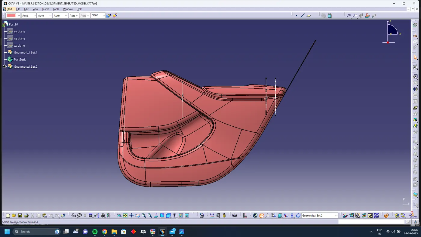
we are tasked to develope a door trim panel with all the b side features with help of the give surface model
Parts
- Arm Rest
- Map Pocket
- Bottle Holder
- Lower Substrate
we need to create all the parts using the surface by following the design rules
Arm Rest
Class A
First Extract the arm rest surface from the master surface and check if the surface has any patches
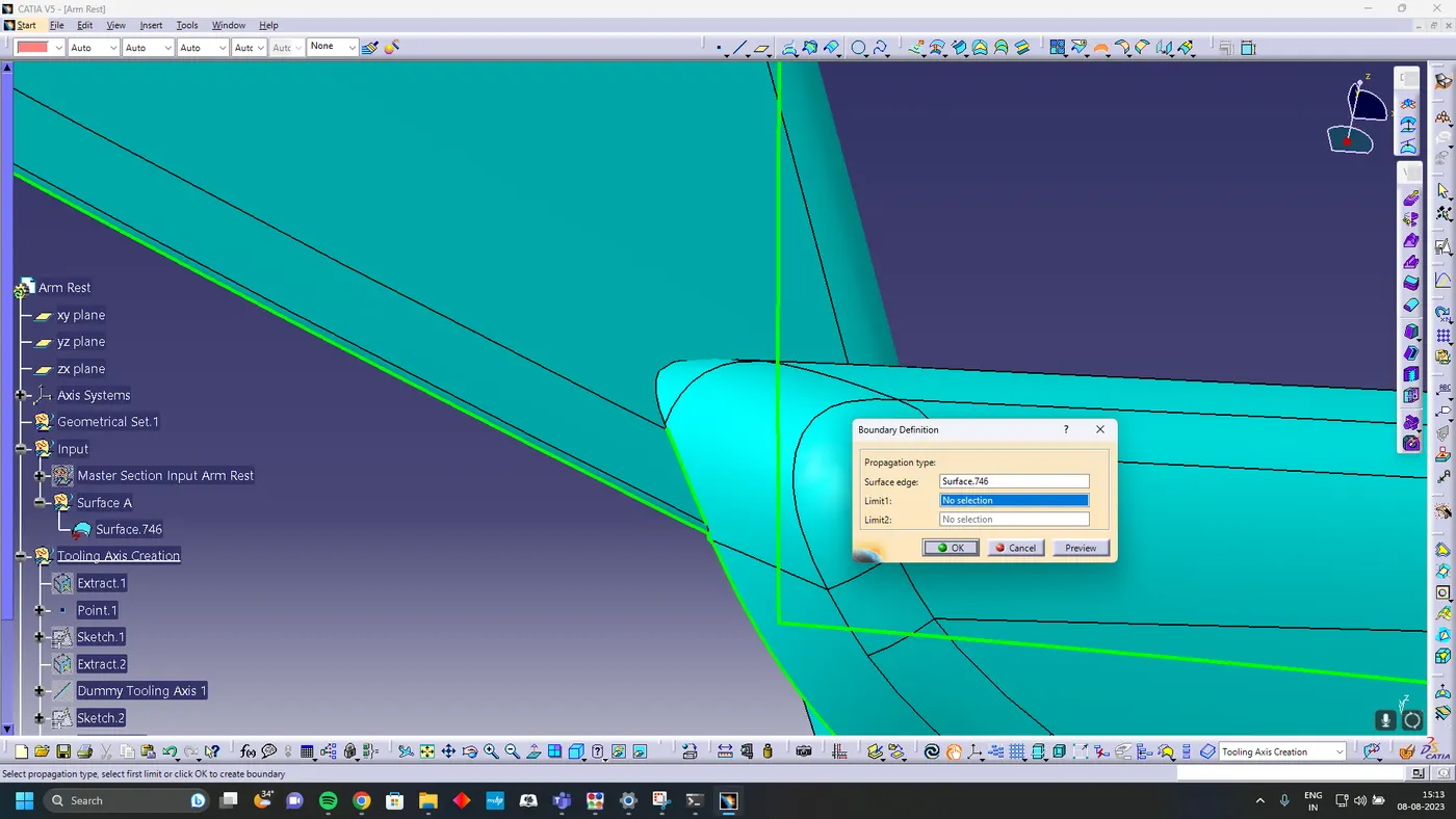
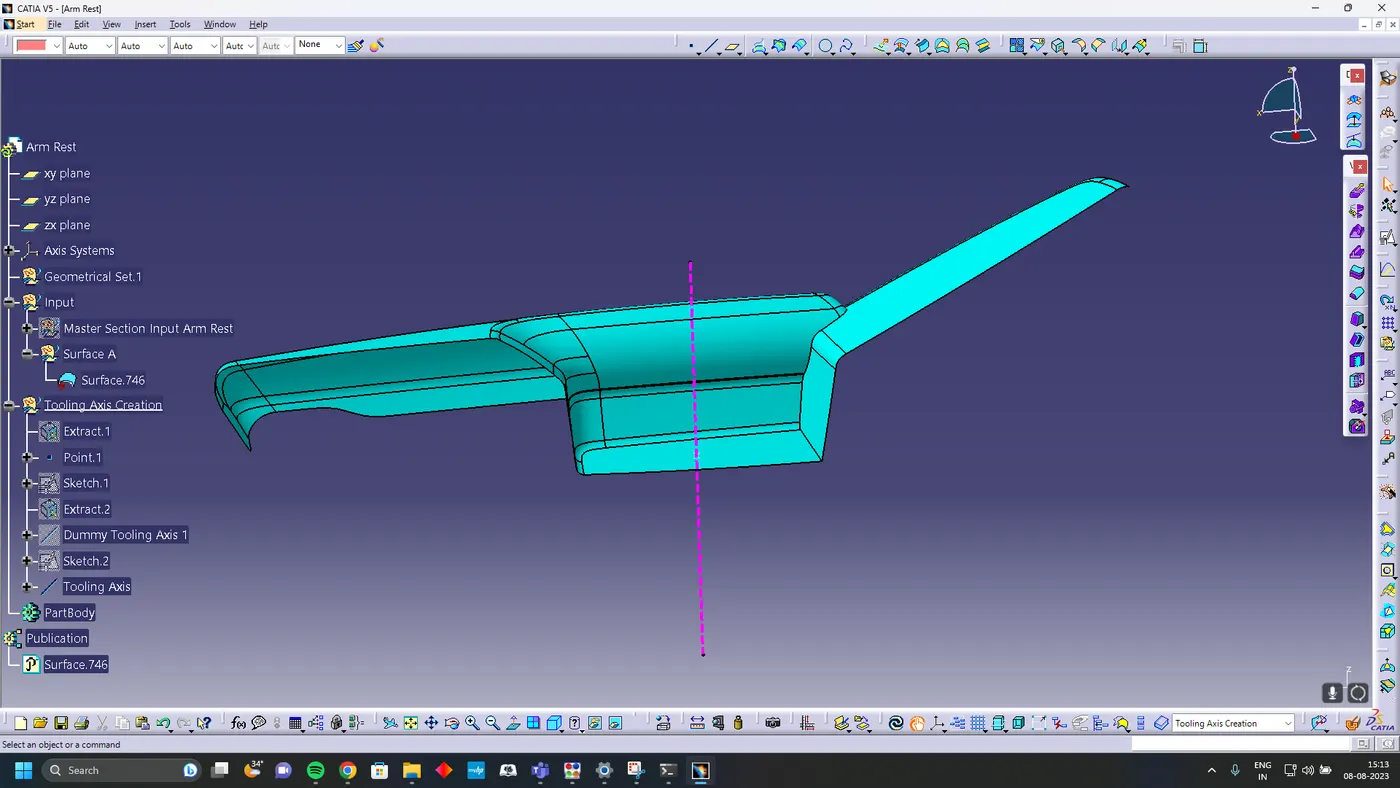
Fix the Patch in the A surface
Tooling Axis Creation
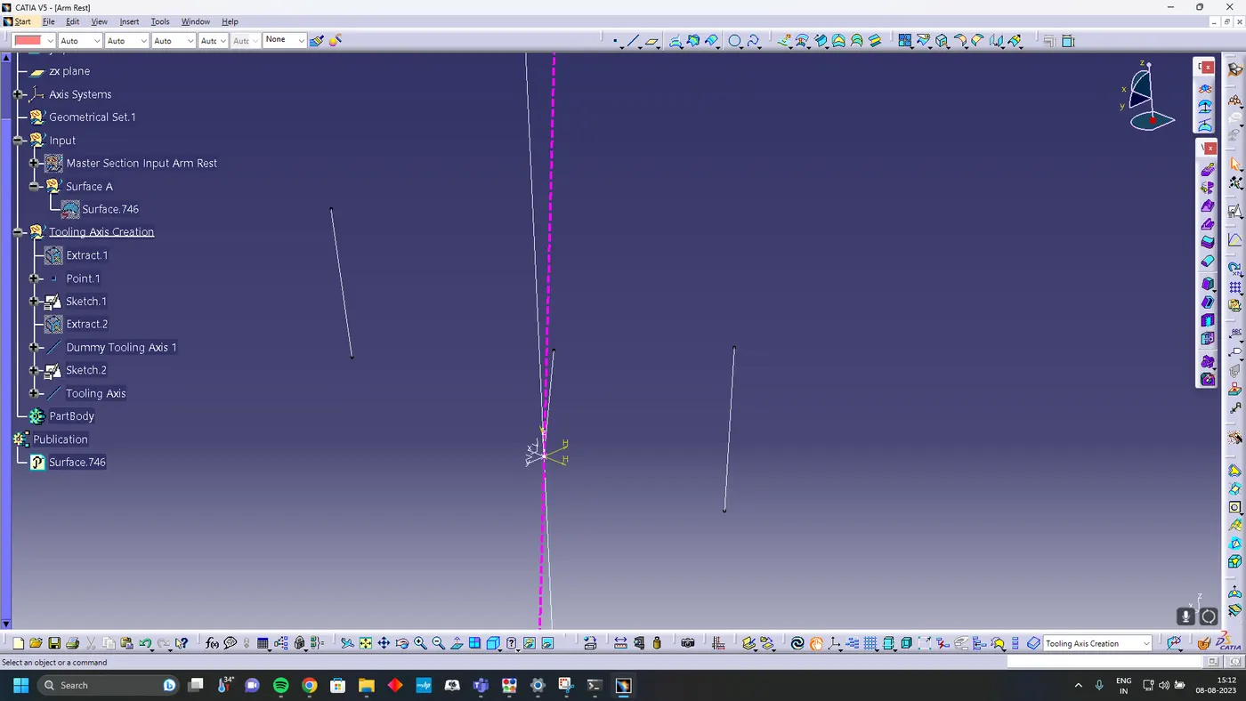
Using line bisecting method create the tooling axis for the arm rest
Surface B
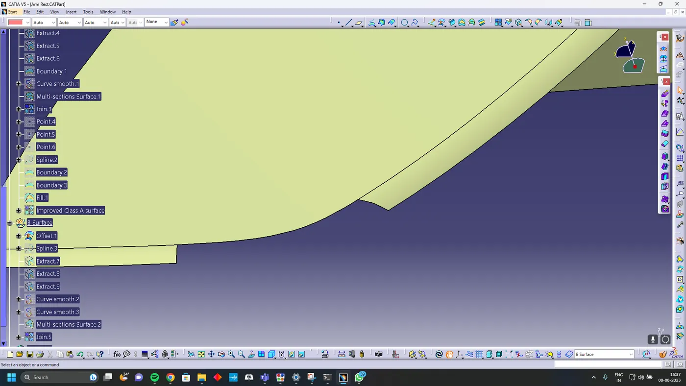
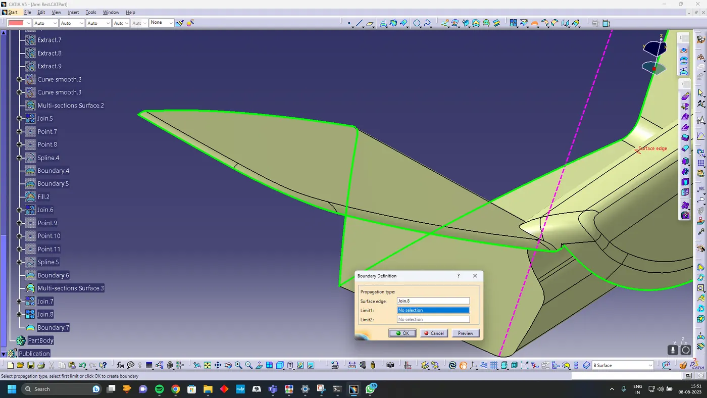
offset the surface A for 2.5 mm and close the open patches
Surface C creation
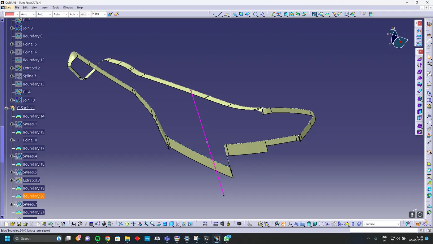
using sweep command and with tooling axis create class C surface
Surface A and C join
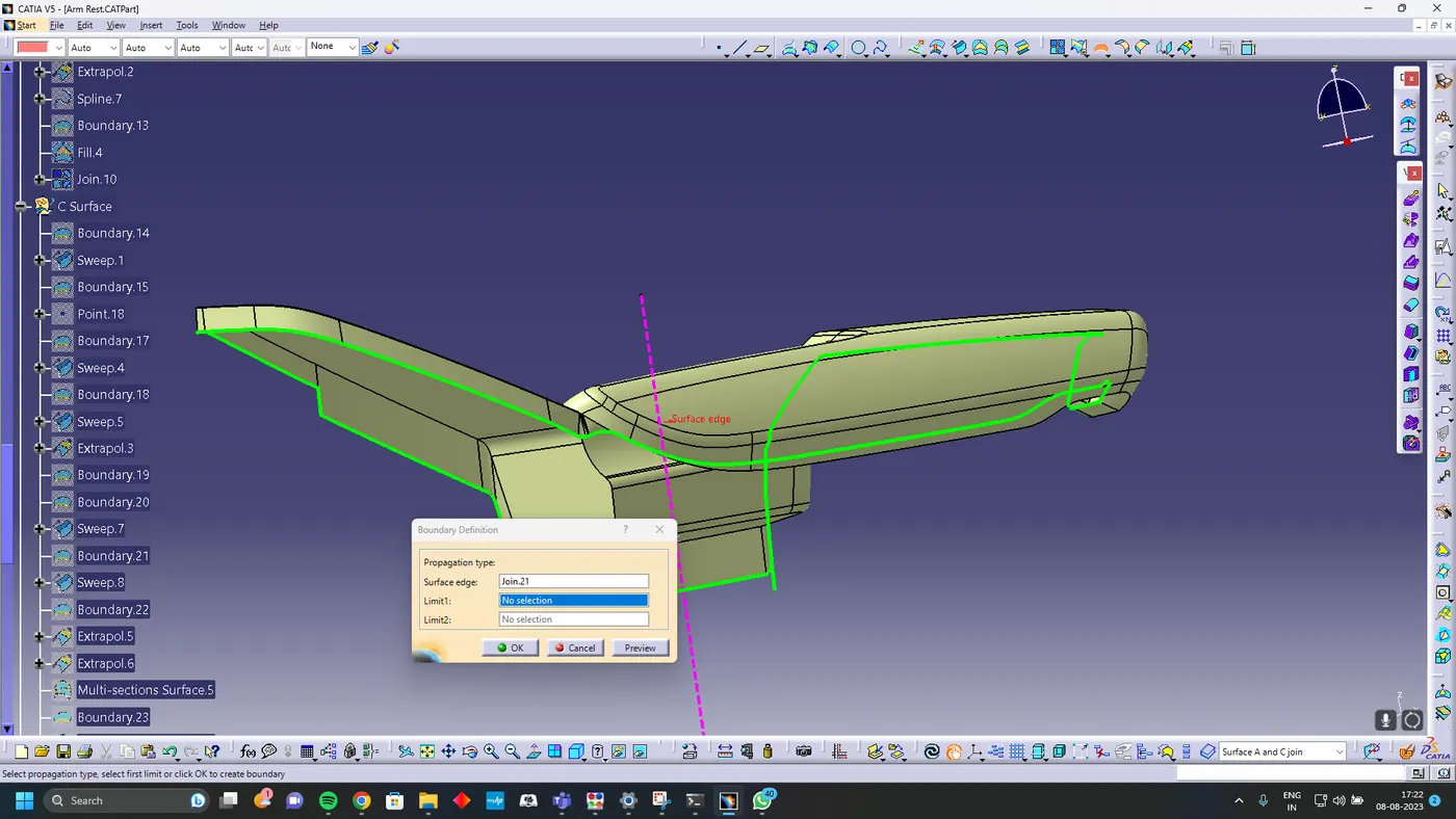
Join surface A and C using join command
Final Trim
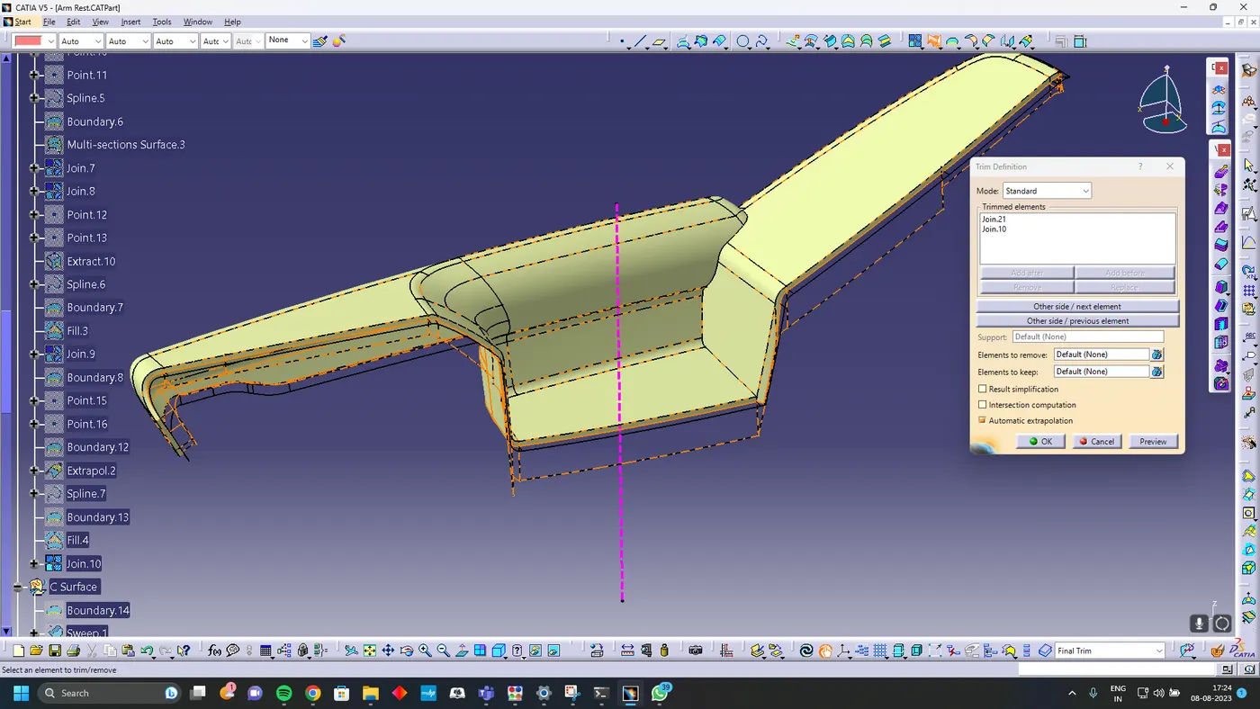

Trim surface B with Surface C and A join
Soild Body
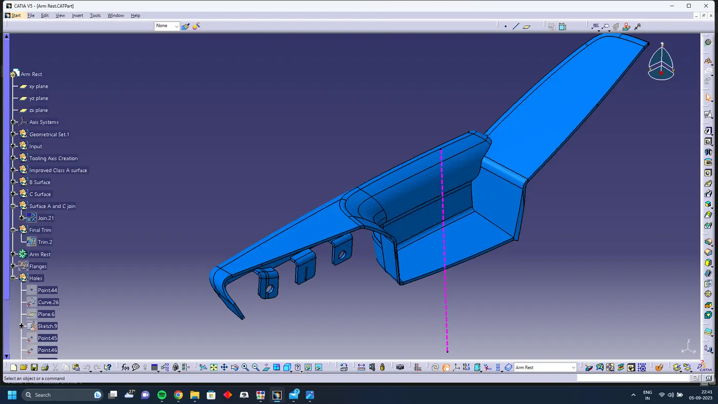
Using Closed body command in the Part design convert the surface into solid
Map Pocket
Surface A
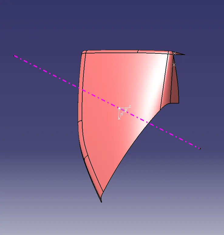
First Extract the arm rest surface from the master surface and check if the surface has any patches
Tooling Axis
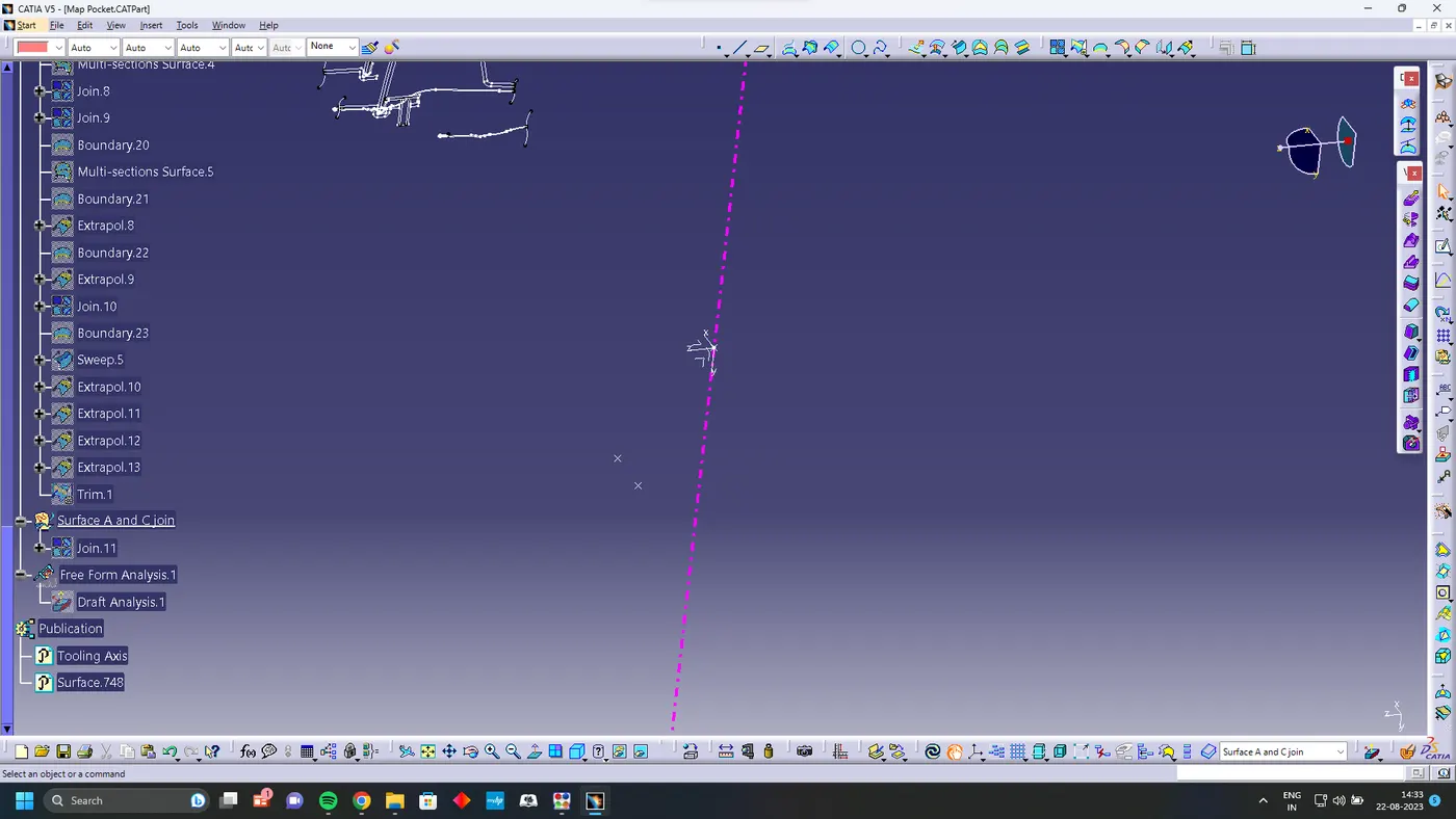
Using line bisecting method create the tooling axis for the arm rest
Surface B
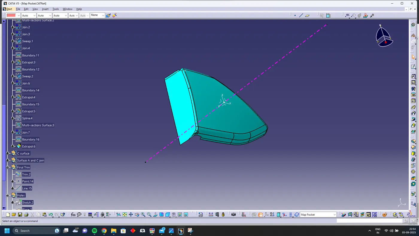
offset the surface A for 2.5 mm and close the open patches
Surface C
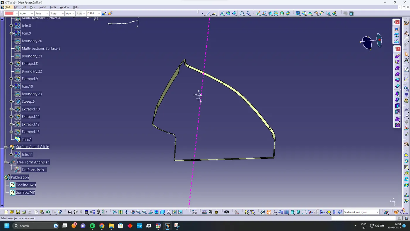
using sweep command and with tooling axis create class C surface
Surface A and C JOin
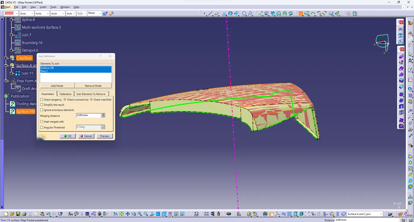
Join surface A and C using join command
Final Trim
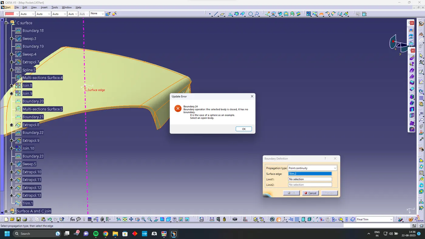
Using Closed body command in the Part design convert the surface into solid
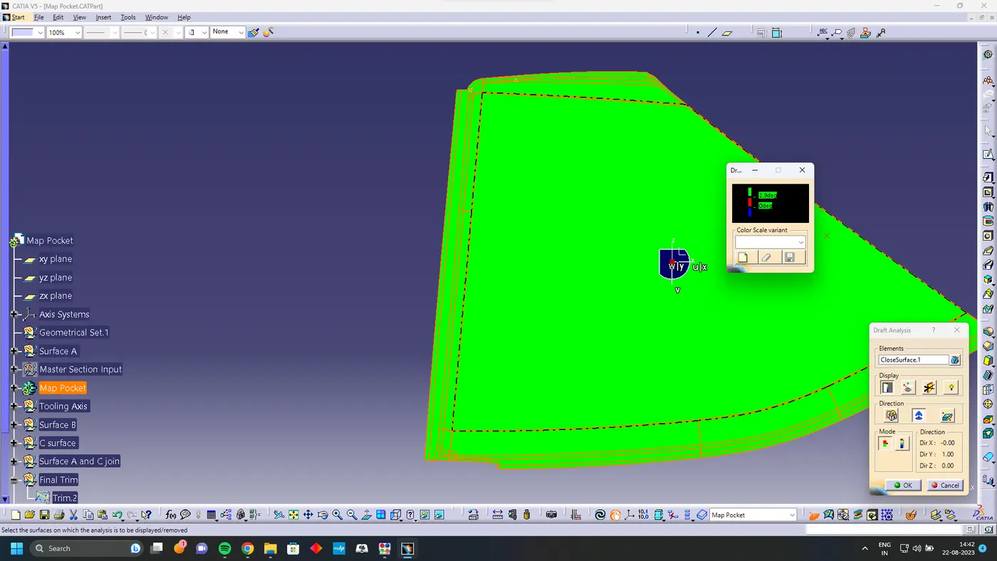
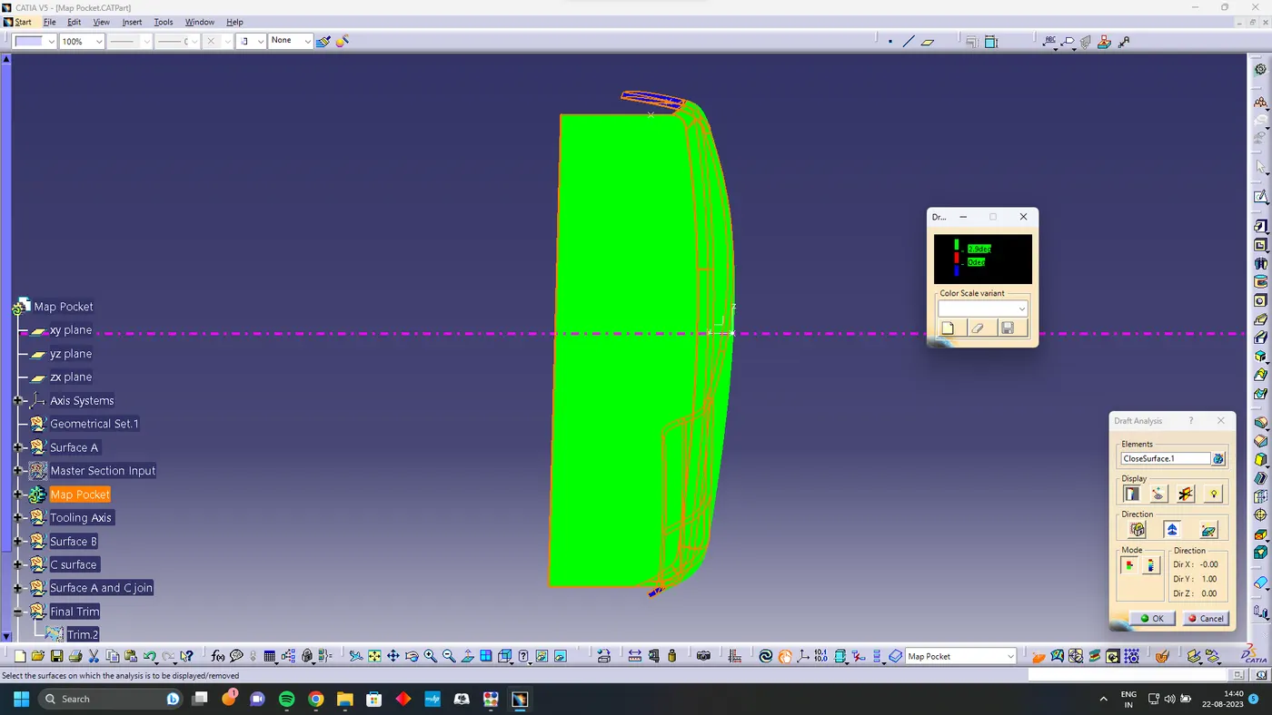
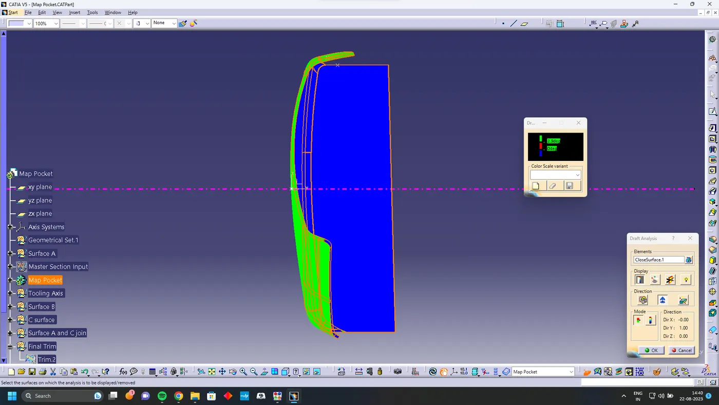
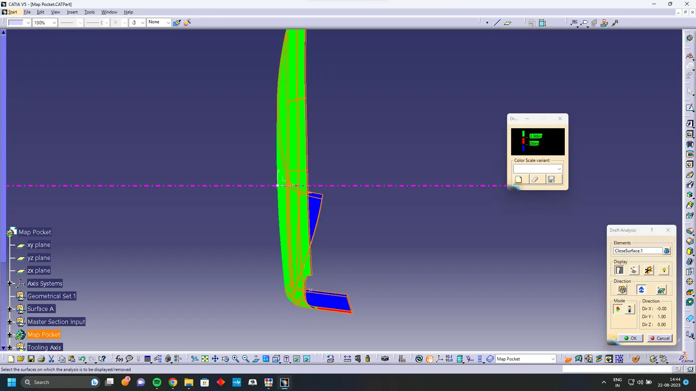
Draft Analysis
Solid Body
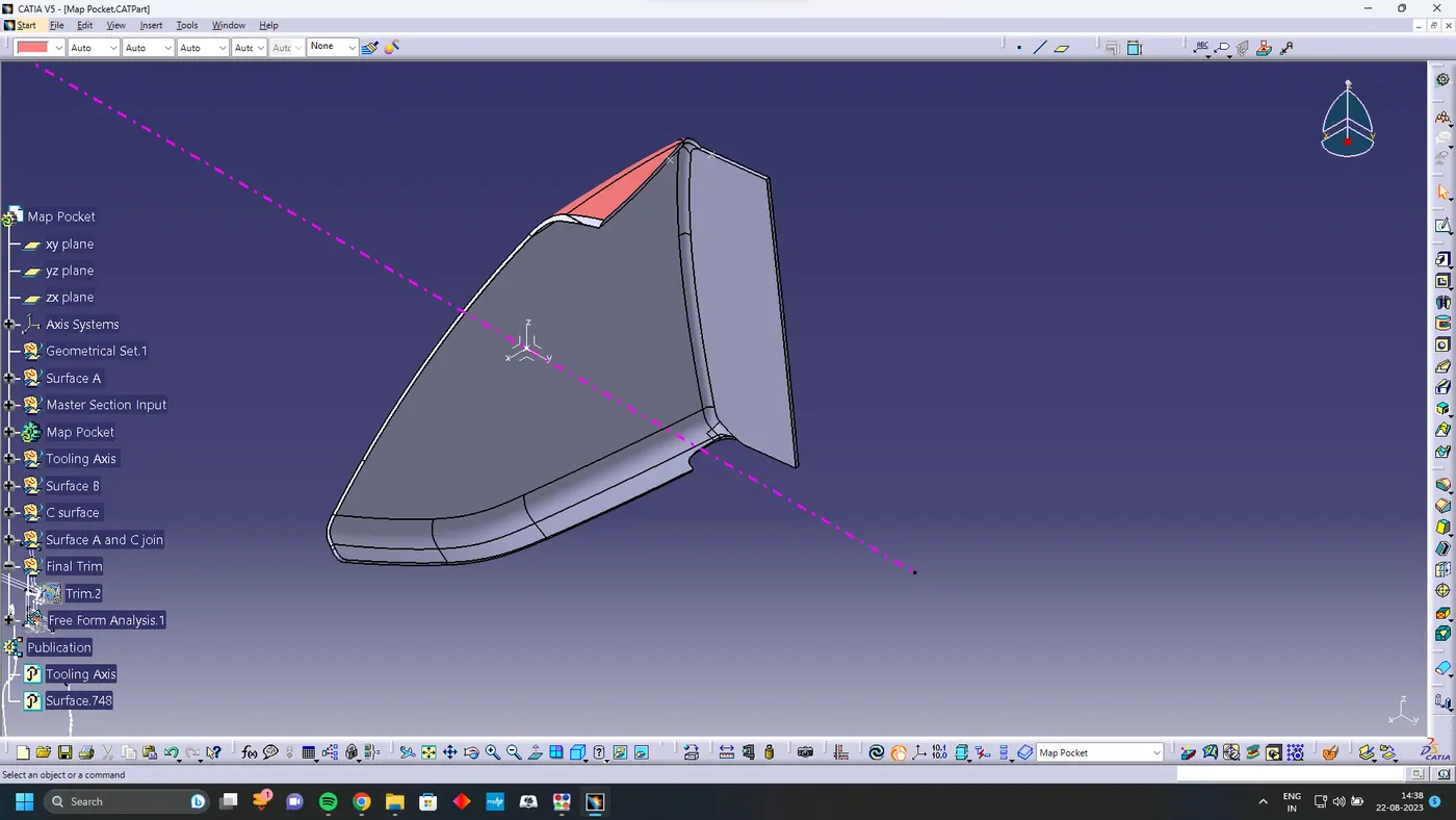
Using Closed body command in the Part design convert the surface into solid
Bottle Holder
Surface A
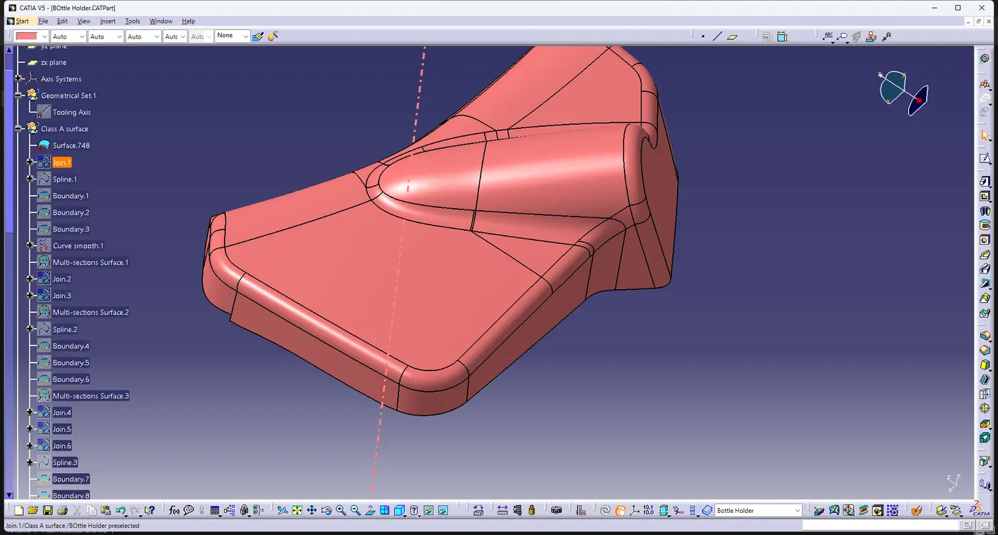
First Extract the arm rest surface from the master surface and check if the surface has any patches
Tooling Axis
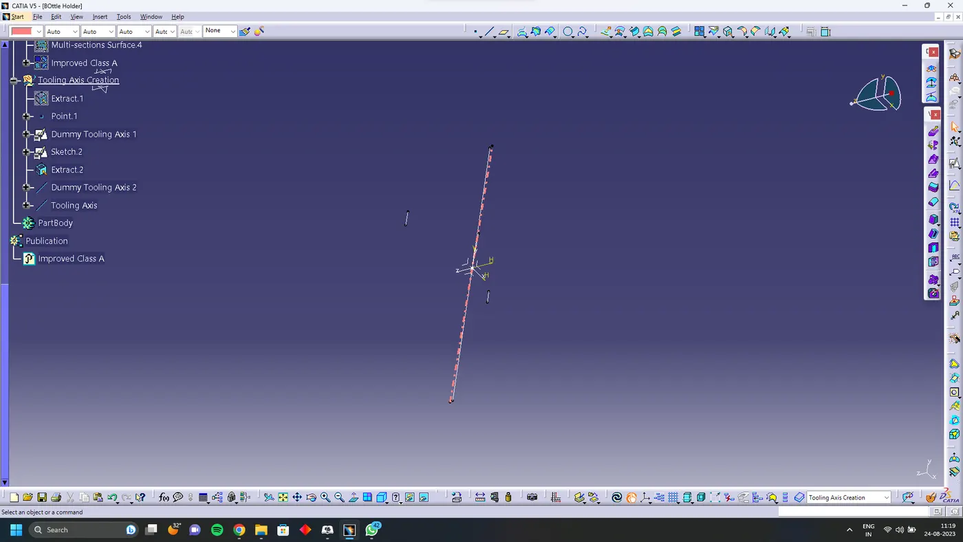
Using line bisecting method create the tooling axis for the arm rest
Surface B
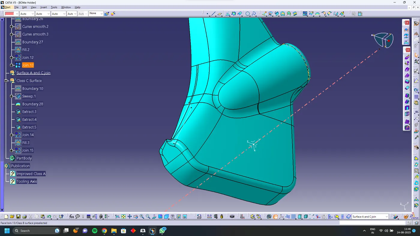
offset the surface A for 2.5 mm and close the open patches
Surface C
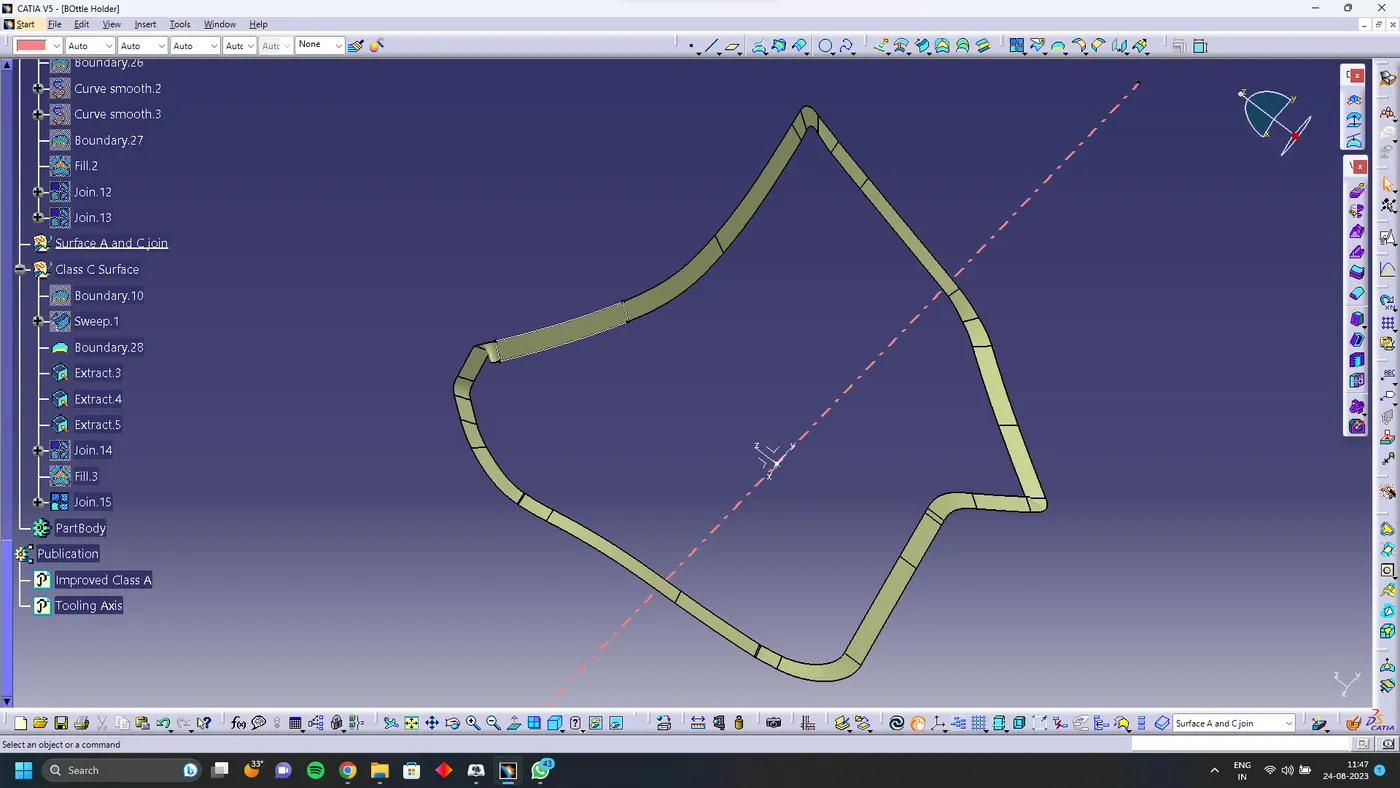
using sweep command and with tooling axis create class C surface
Surface A and C join
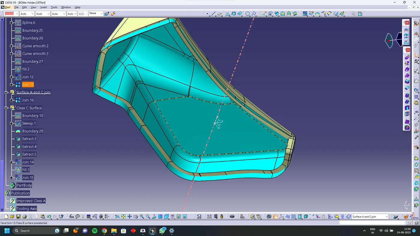
Join surface A and C using join command
Final Trim
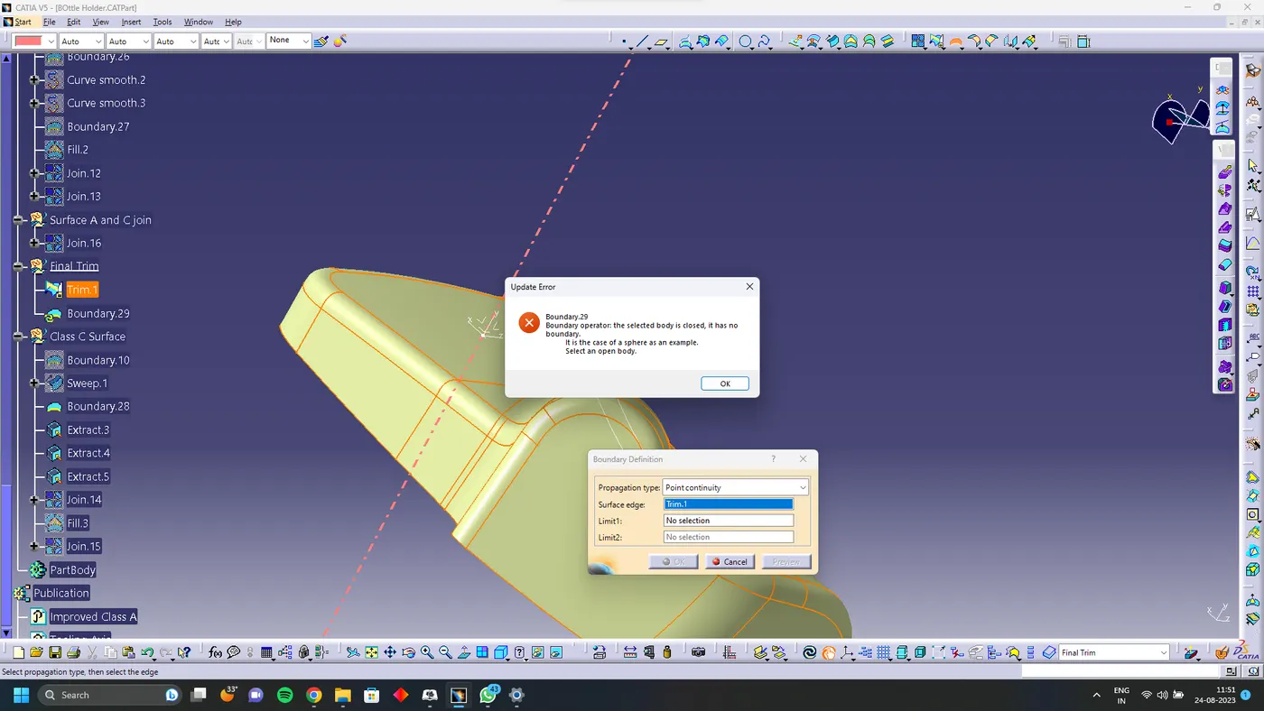
Trim surface B with Surface C and A join
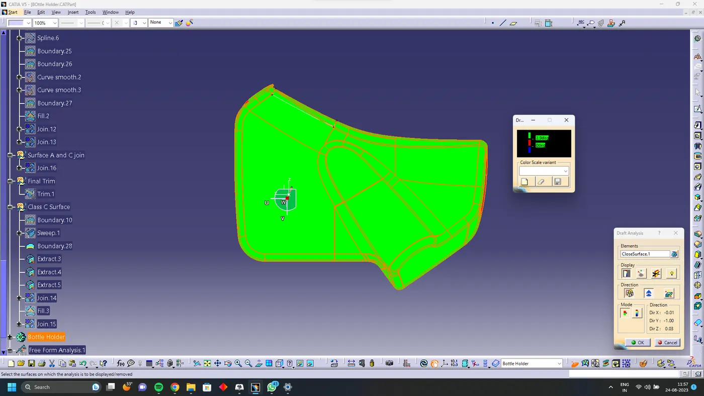
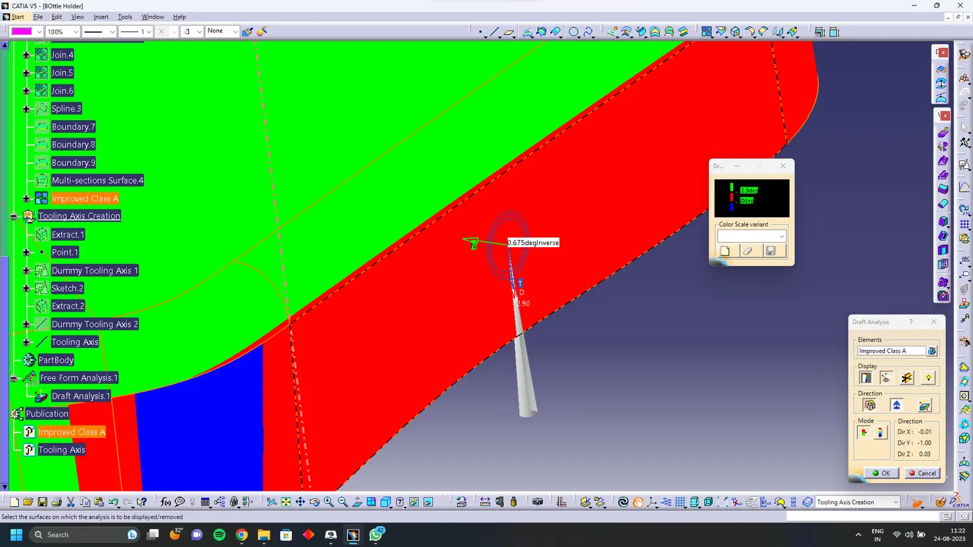
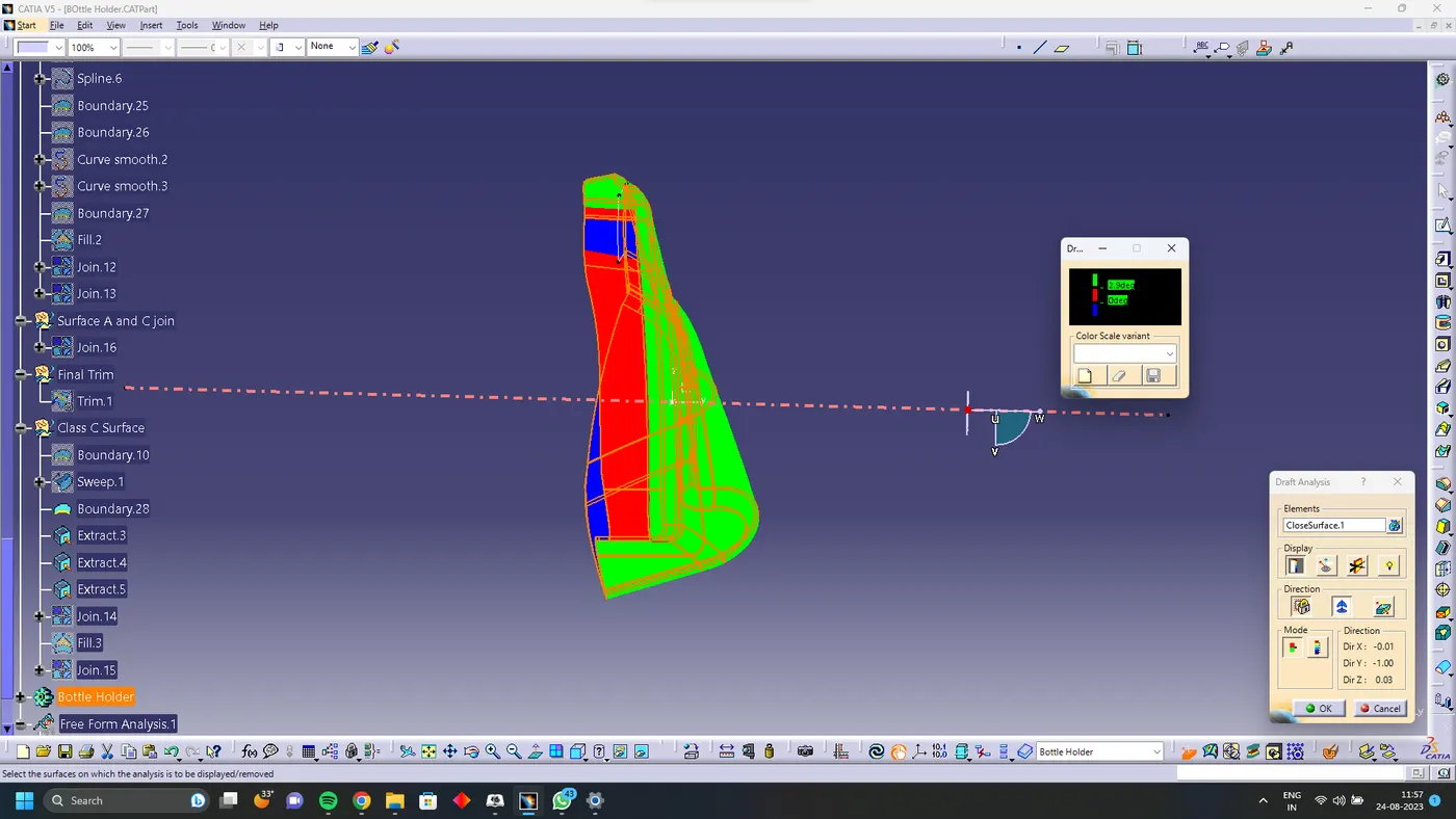
Draft Analysis
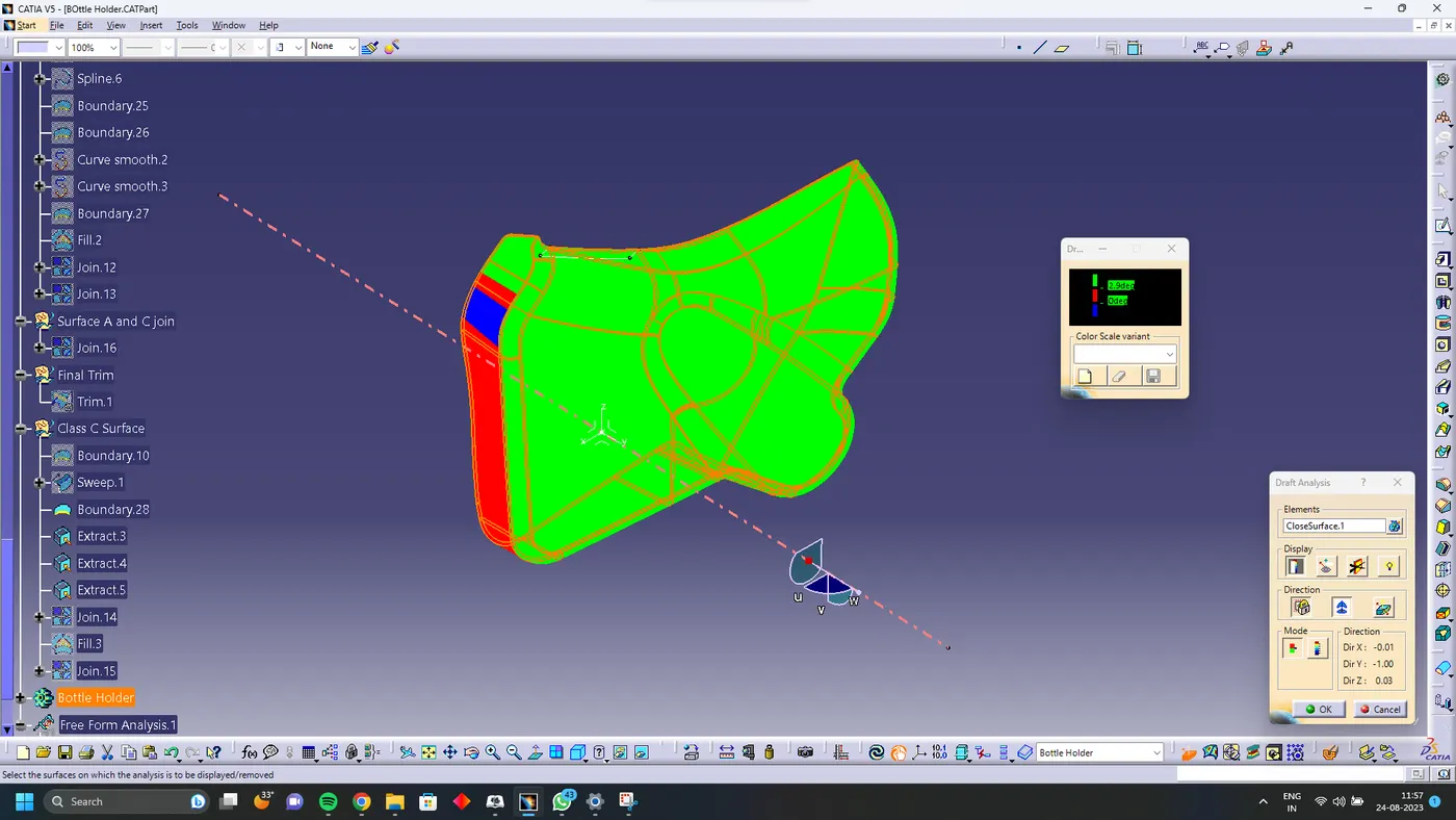
Solid Body
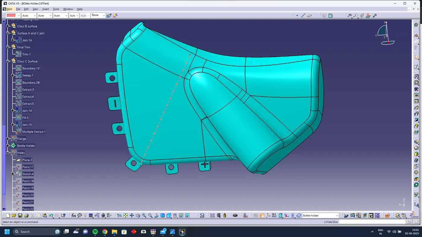
Using Closed body command in the Part design convert the surface into solid
Lower Substrate
Surface A
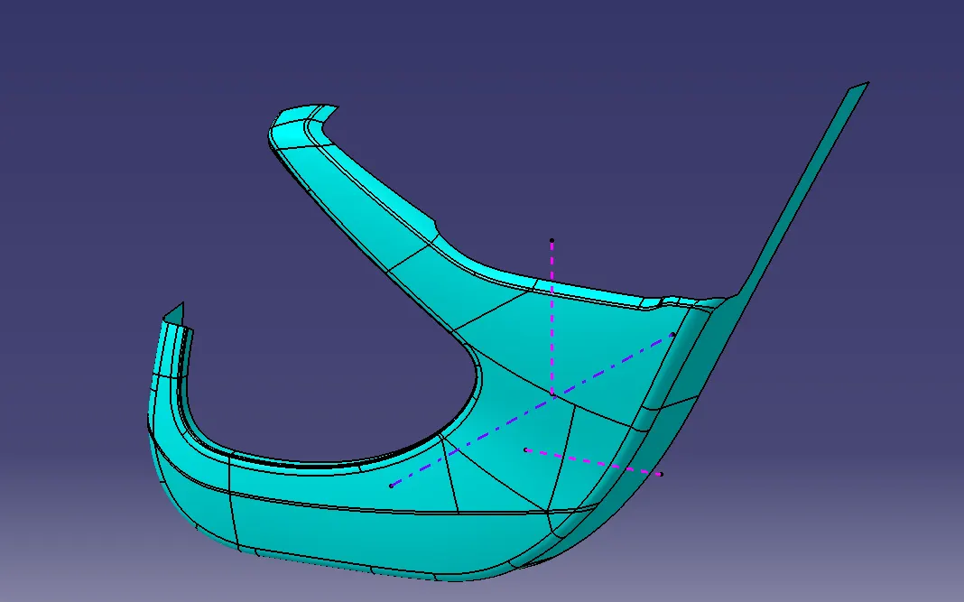
First Extract the arm rest surface from the master surface and check if the surface has any patches
Fix the Patch in the A surface
Surface B
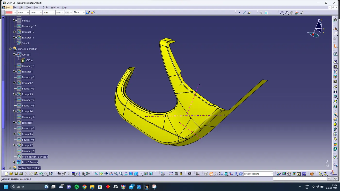
offset the surface A for 2.5 mm and close the open patches offset the surface A for 2.5 mm and close the open patches
Surface C
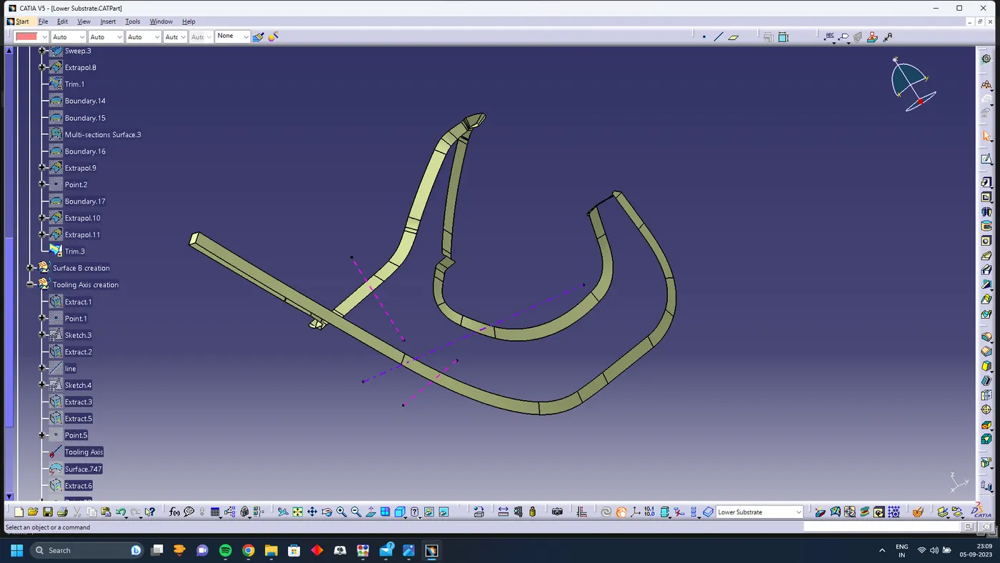
using sweep command and with tooling axis create class C surface
Surface A and C join
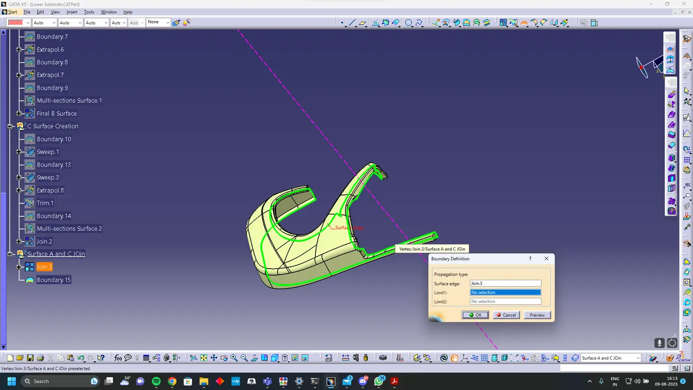
Join surface A and C using join command
Final Trim
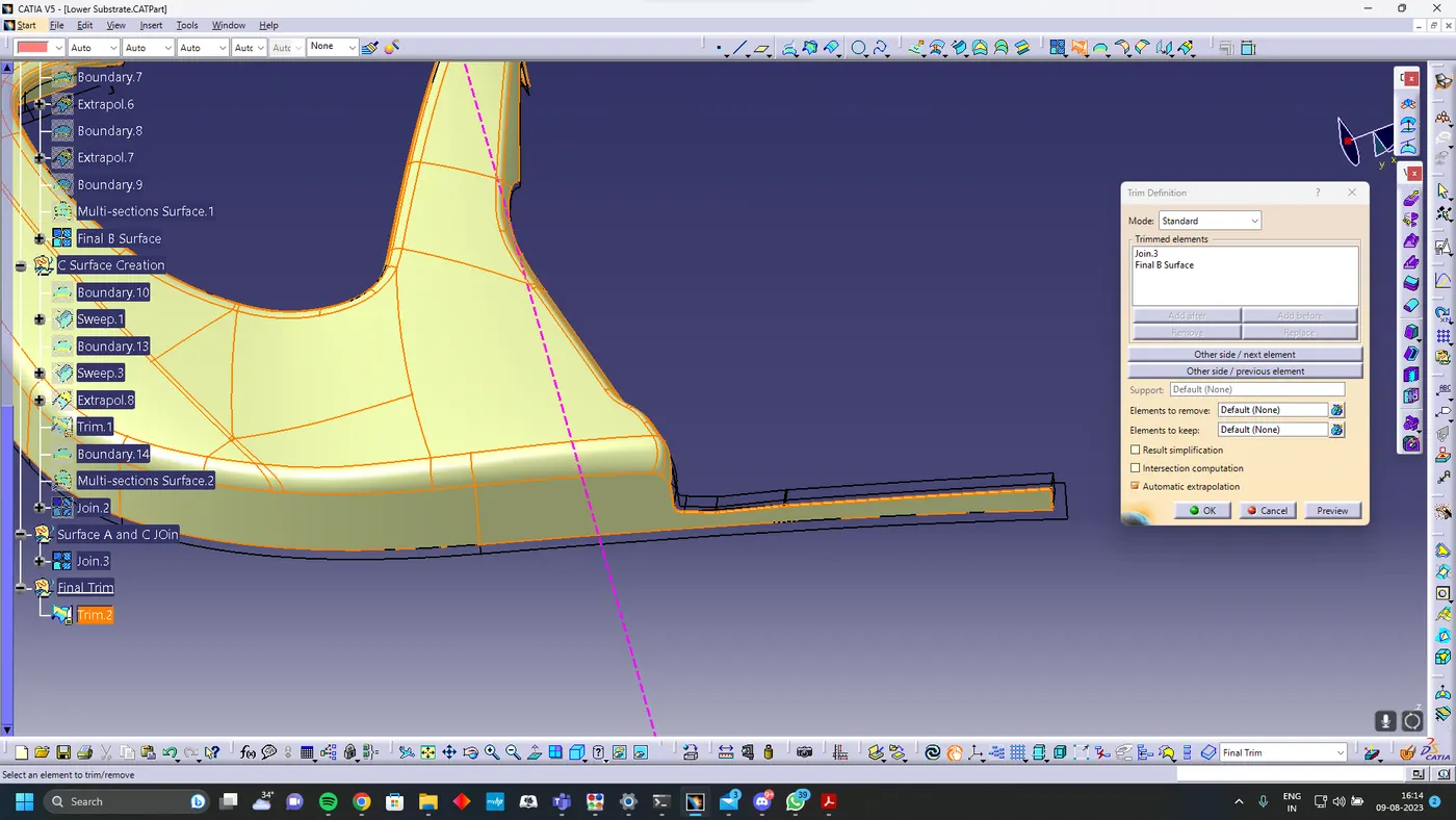
Trim surface B with Surface C and A join
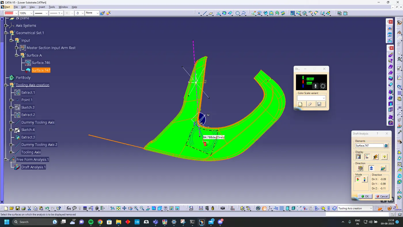
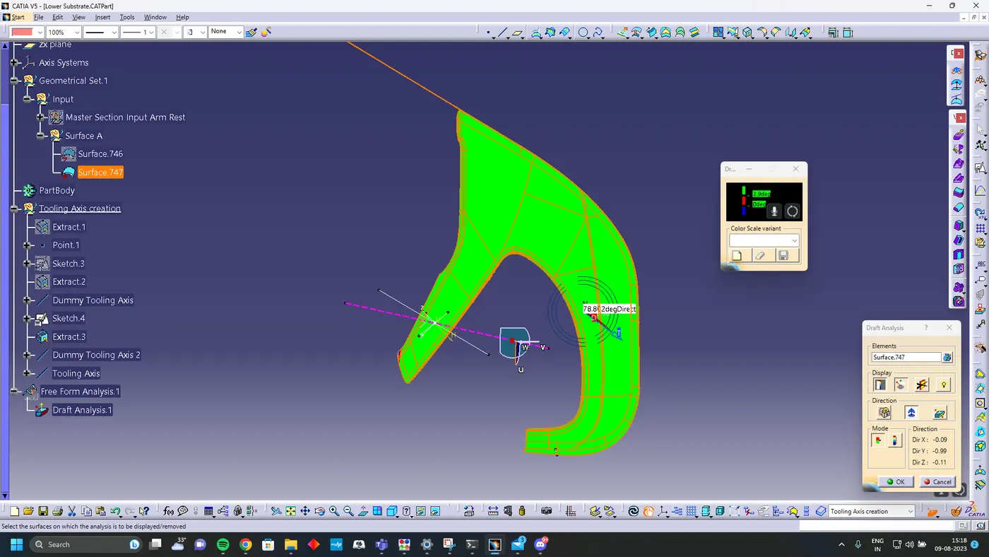
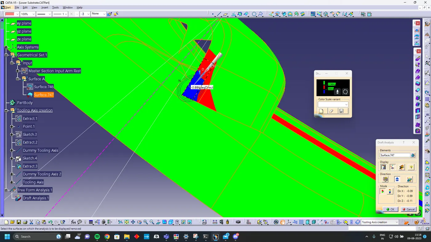
Draft Analysis
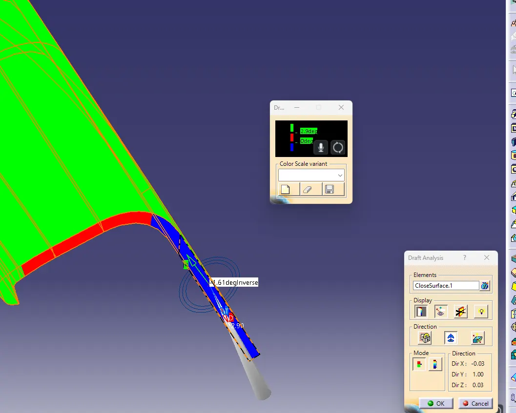
Solid Body
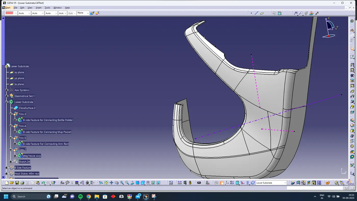
Using Closed body command in the Part design convert the surface into solid
B side Features
The B side features are used to connect the parts together
- Heat stakes
- Locators
- Dog House
Heat stakes
Heat stakes are used in thermoplastics to assemble two parts together by locally heating and cooling the plastic material and allowing it to reform itself and act as a joint for the two materials.
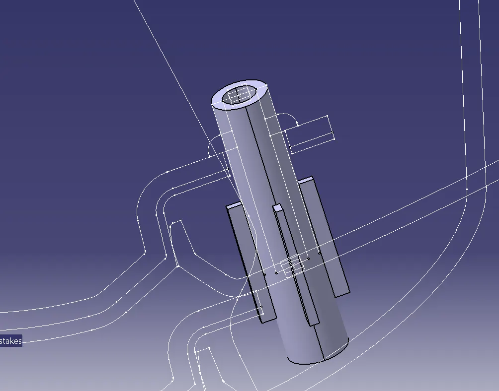
Using the Master section The heat stakes are created
Locators
The main purpose of locators is to facilitate proper locking of two components together while assembling and arrest the maximum degrees of freedom possible. The two types of locators used are two way locator and four way locator.
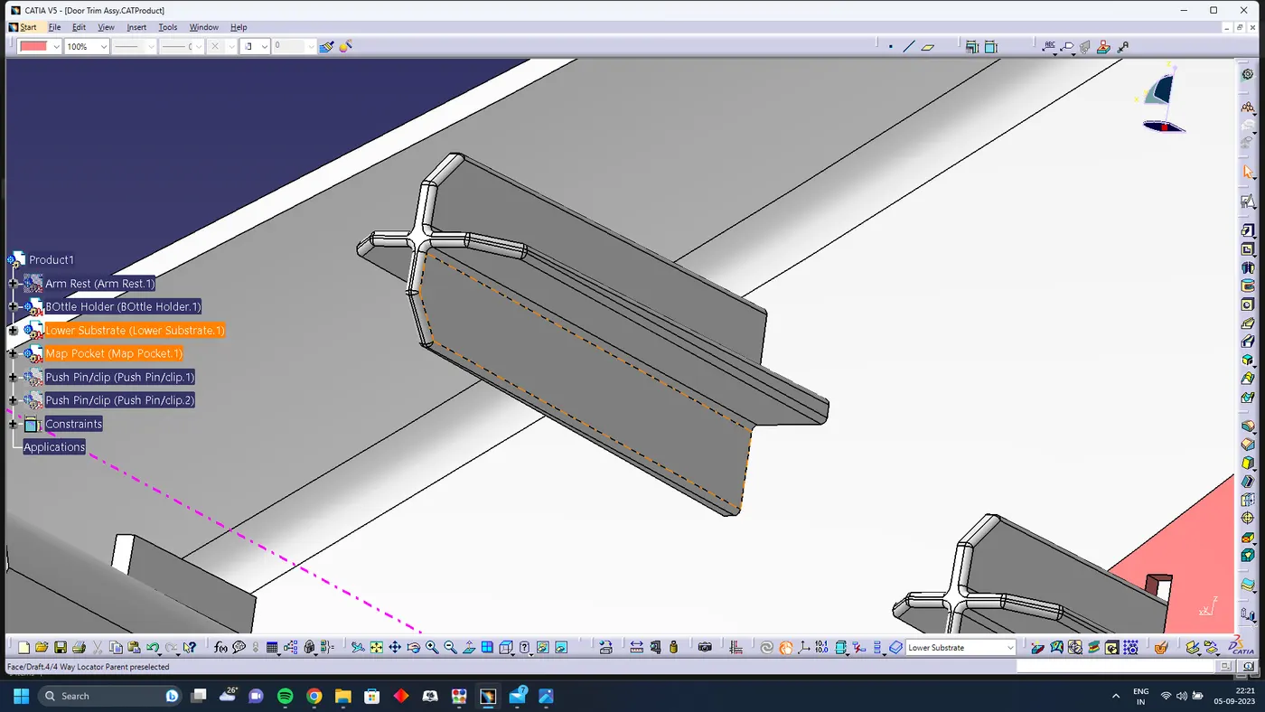
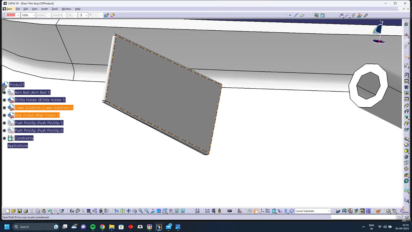
All the faces of locators have minimum draft 0.5 degree
Dog House
The two main purposes of a dog house are to avoid sink marks and to house various other engineering features like screw boss, locators, push clips etc. In this case, the dog house is designed to house the push clips The dog house designed for the push clip features a slot on the top face to accommodate the push clip
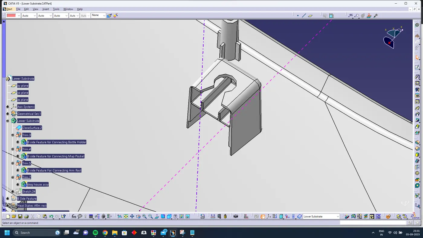
Draft Analysis on Dog house
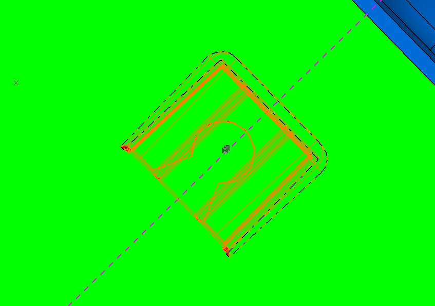
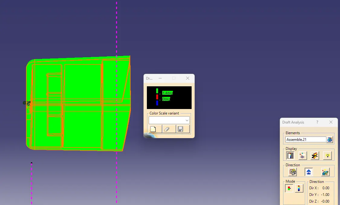
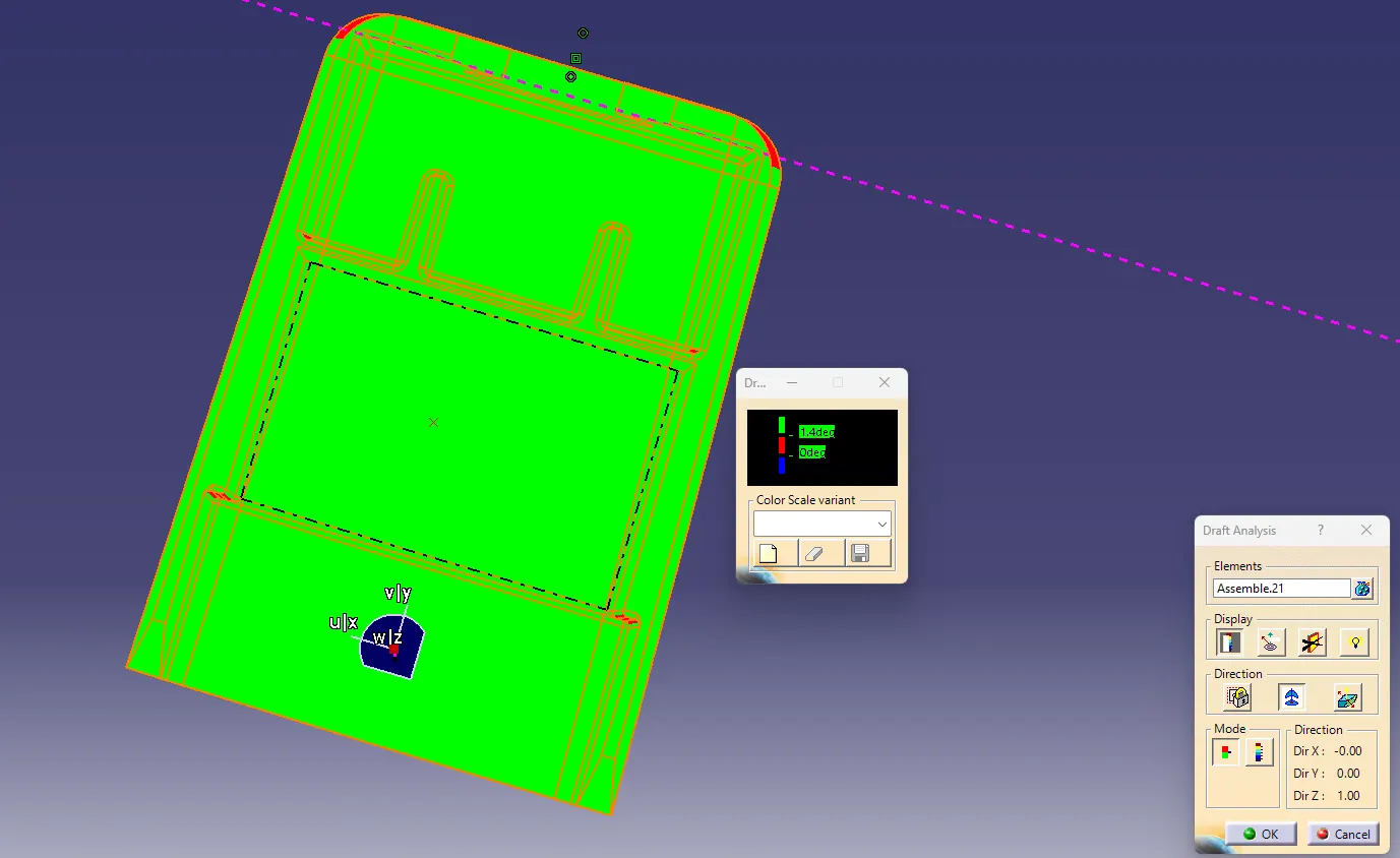
1.5 deg of draft angle is provided of dog house
Flange
Flanges are created using the mastersection given
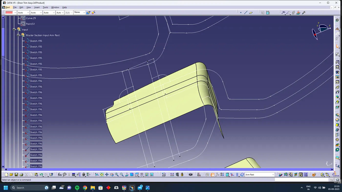
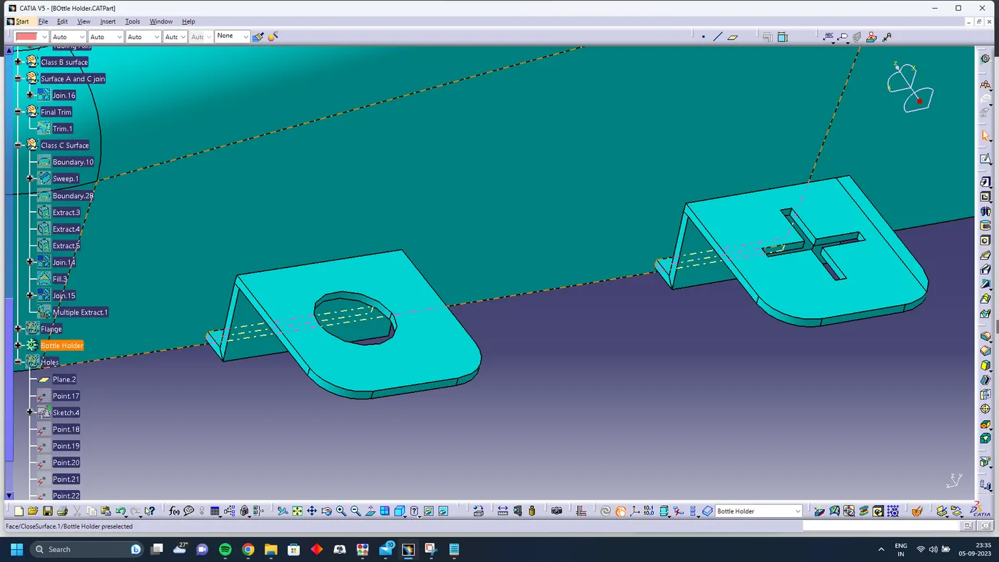
Flanges are created according to the b side features on the lower substrate
Lower Substrate with all B side features
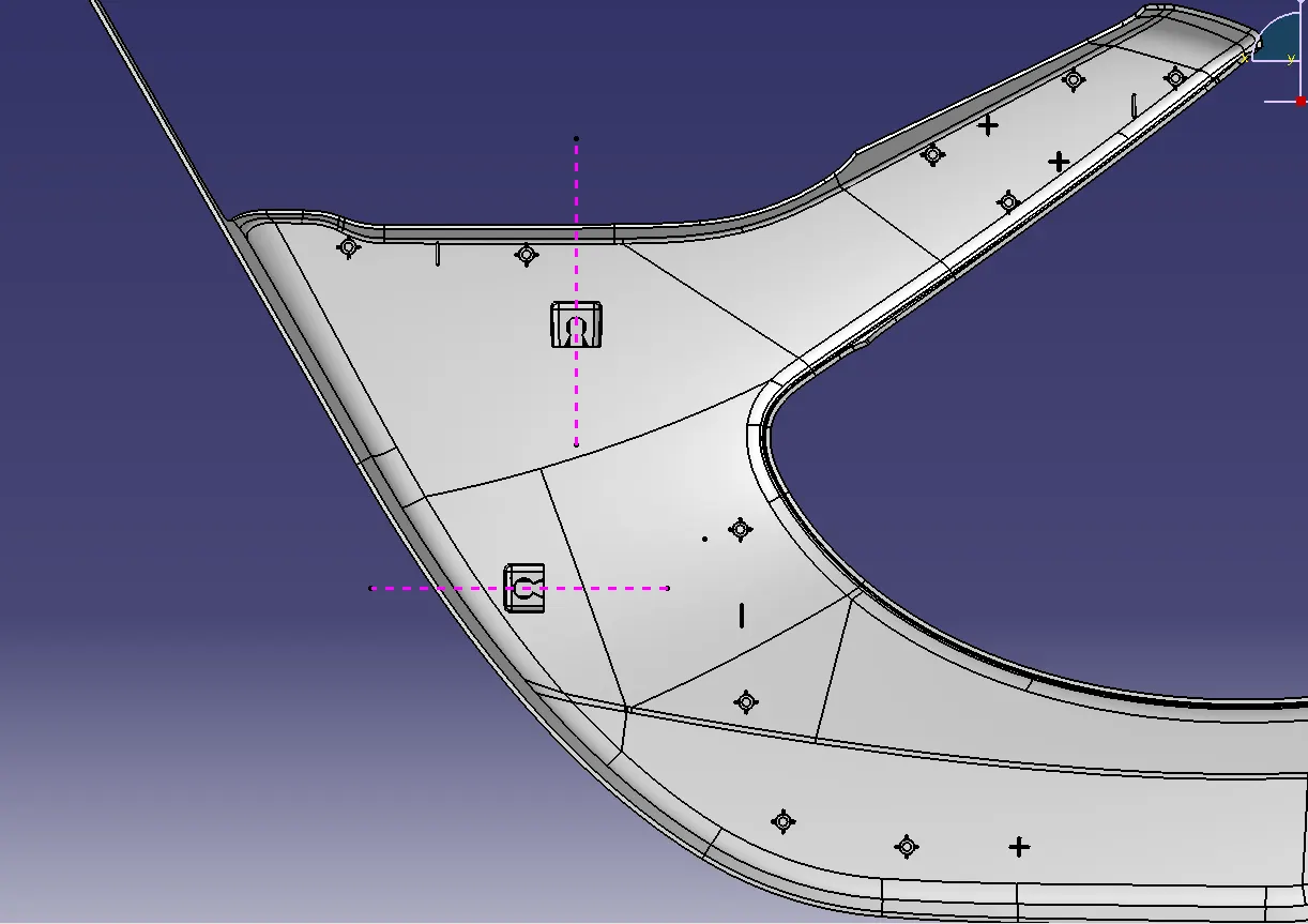
Lowersubstrate with locators , heatstakes and dog house
Arm Rest ( with flange )
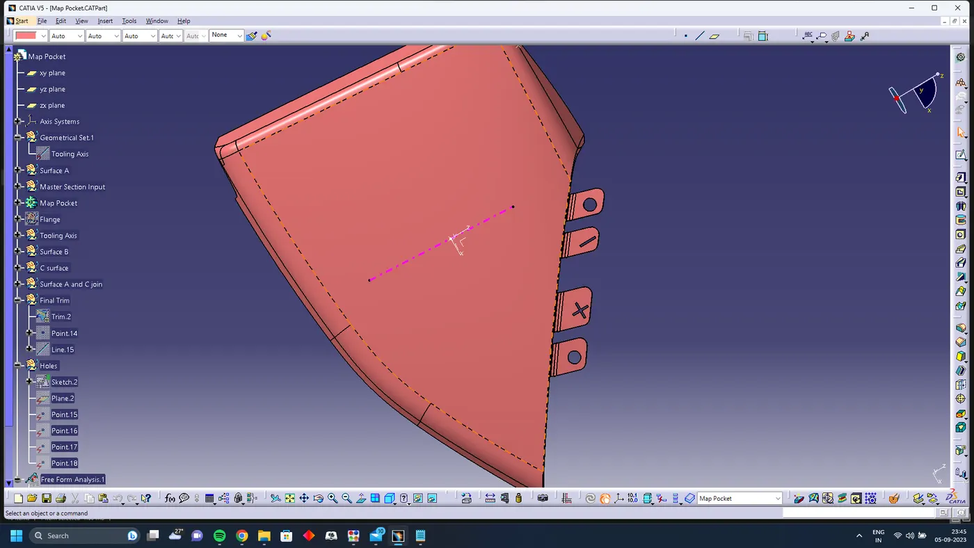
Map Pocket ( With Flange )
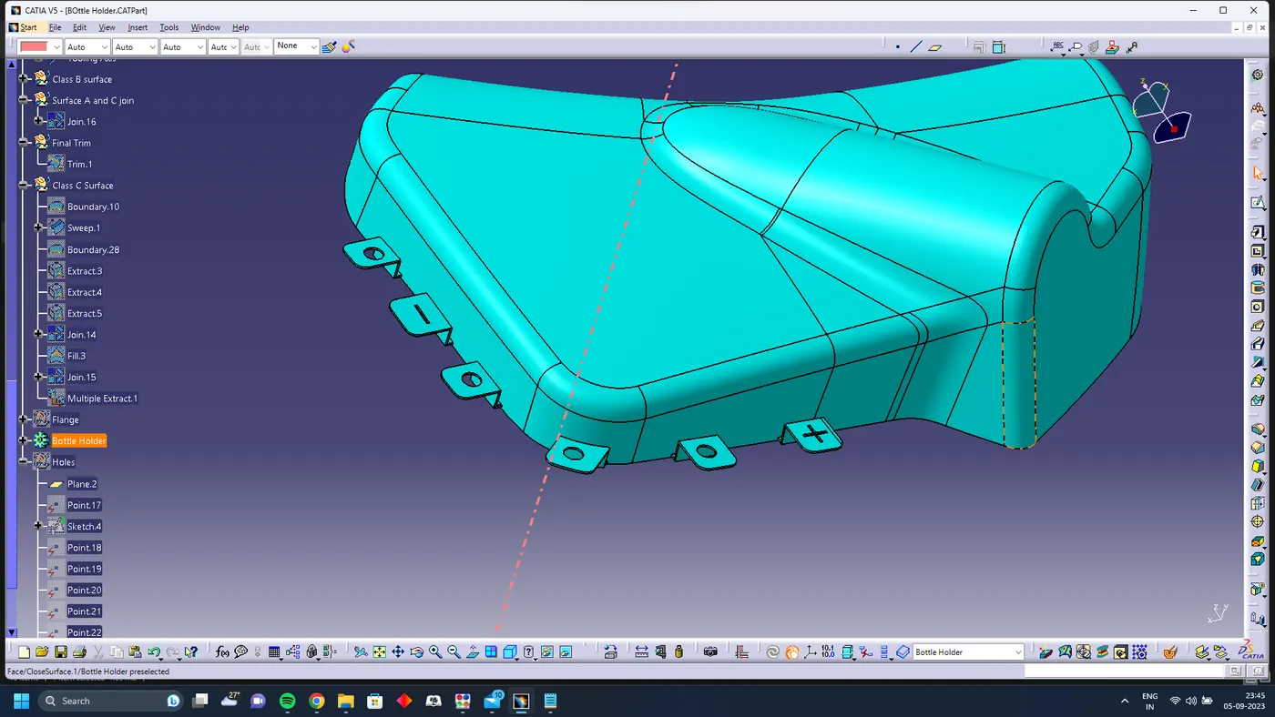
Bottle Holder (with flange )
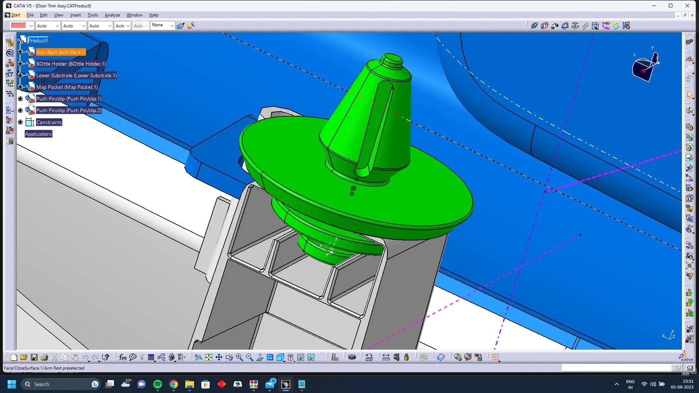
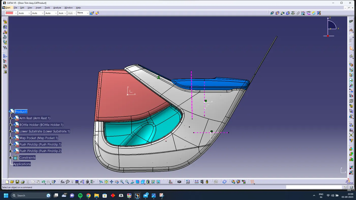
Push Pin Assy
Assembling the push pins to the dog houses
For this create an axis on the push clops and create the axis on the top cut out on the dog house and apply the coincidence constraint.
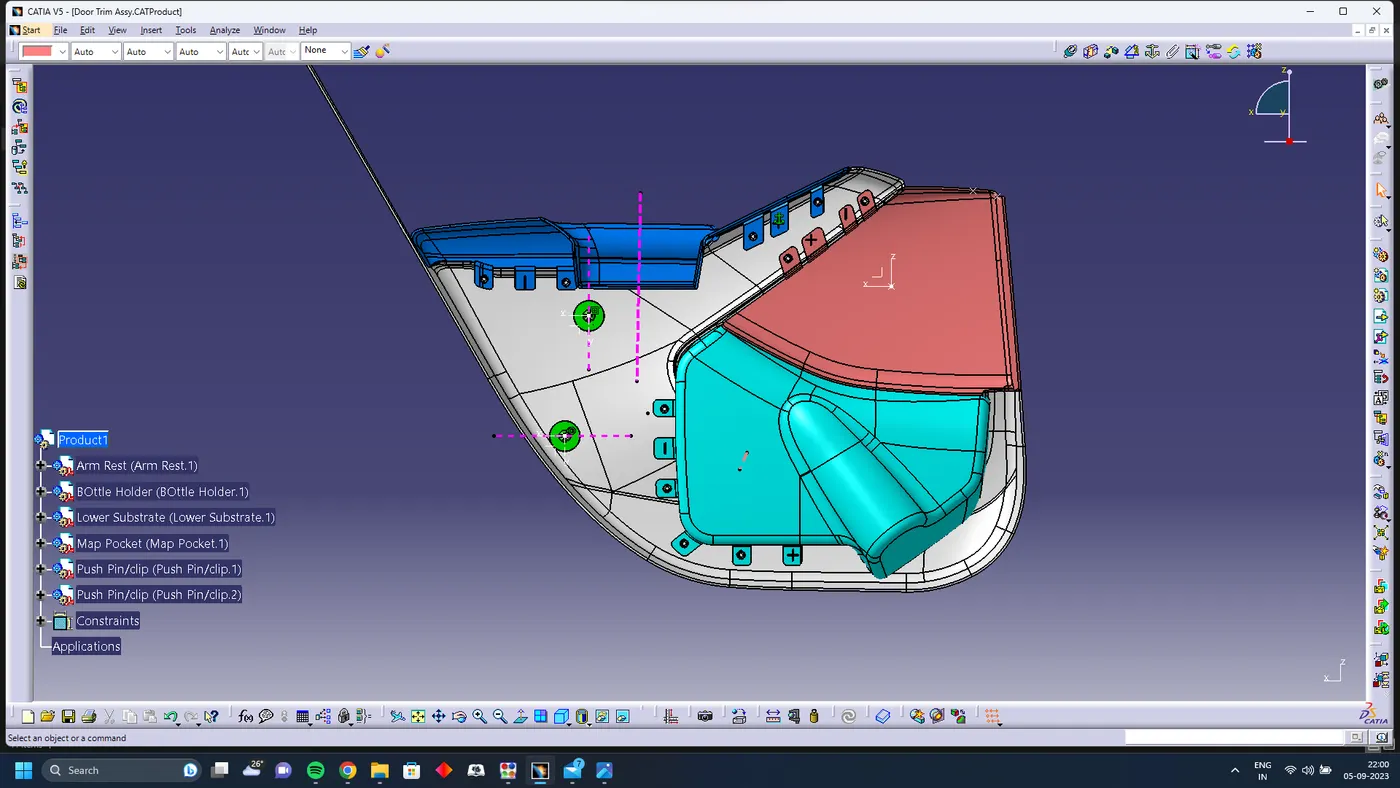
FInal Assmebly
Conclusion
I learned how to create CAD models for plastic parts by taking design rules into account from this project. I became very familiar with the part workbench, surface workbench, and assembly workbench by working on this project on Catia V5. Additionally, I gain confidence using all of the workbenches' various features. Along with this, thinking about manufacturing and assembly aspects gives me ideas for how to design a part.