Week 12- Final project
AIM: - To create a CAD model for door trim panel's parts by considering the given inputs of class A surface along with master section by following the design rules followed in OEM companies.
OBJECTIVES: -
- To create individual tooling axis for the parts and perform draft analysis on the class A surface
- To form a solid body from the given class A surface.
- To decide an attachment strategy for the part and create engineering features in reference from the master section provided
- To perform draft analysis on the solid part model with all engineering features
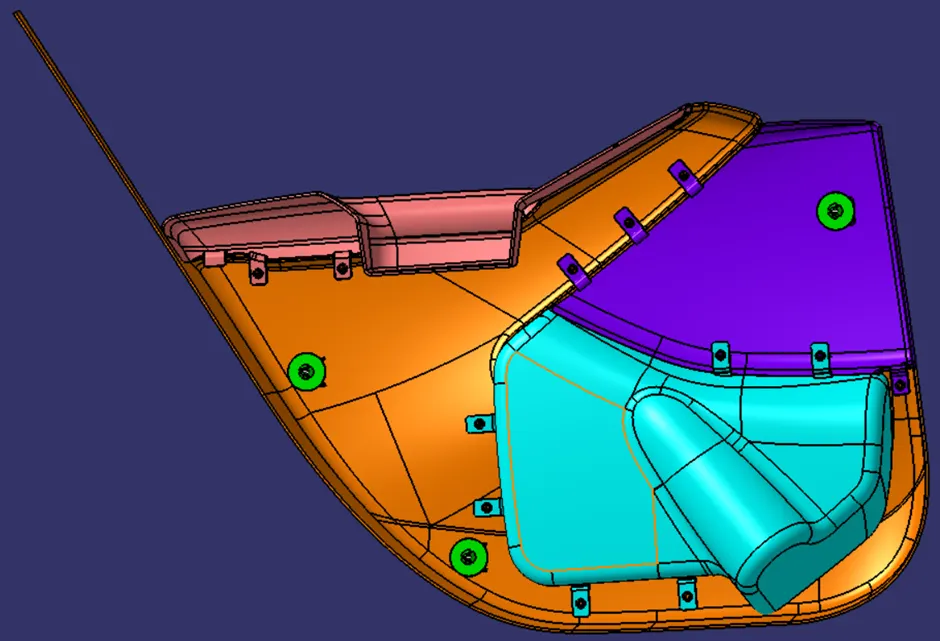
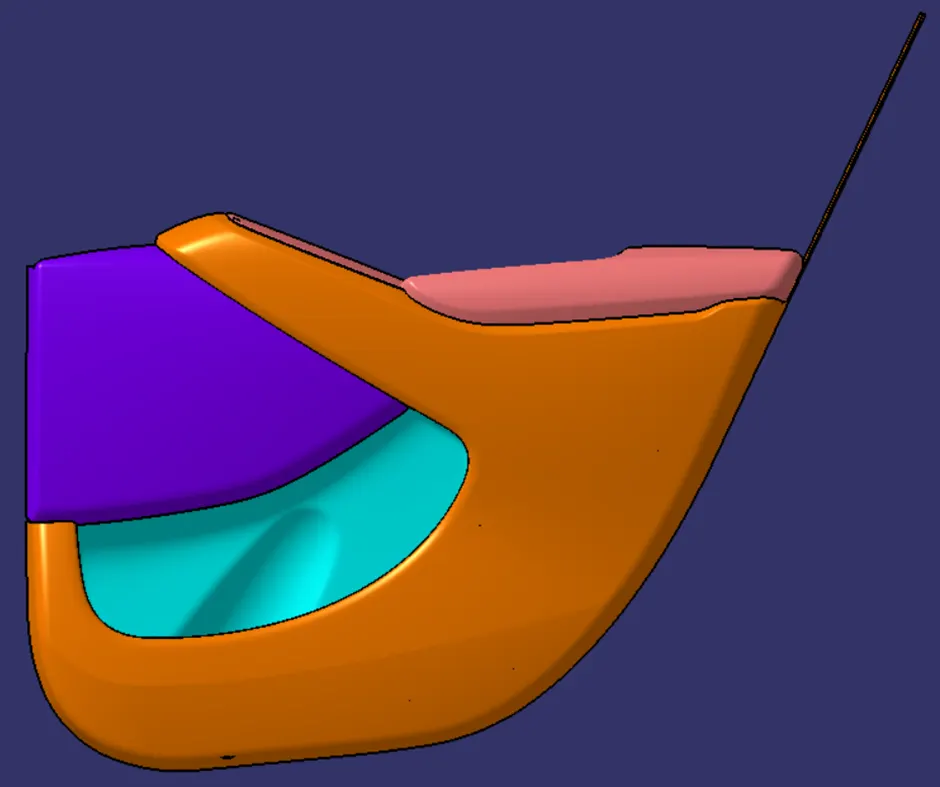
- To assemble all the components together to obtain the final trim.
INPUTS: -
Class A surface with the Master section is given as the input for door trim creation.
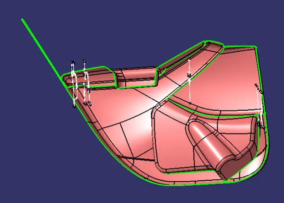
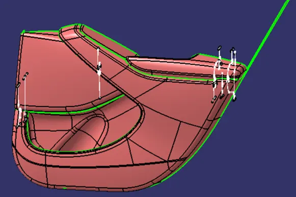
STEPS IN PROJECT COMPLETION: -
1. Class-A surface was extracted from the given surface and checked for any modification required.
2. Tooling Axis were created of the individual component.
3. Class-B and Class-C surface were created with the OEM guidelines.
4. Formed Solid body using the closed surface command.
5. Engineering features were created for attachment of parts.
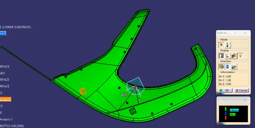
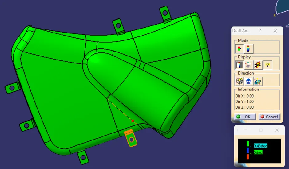
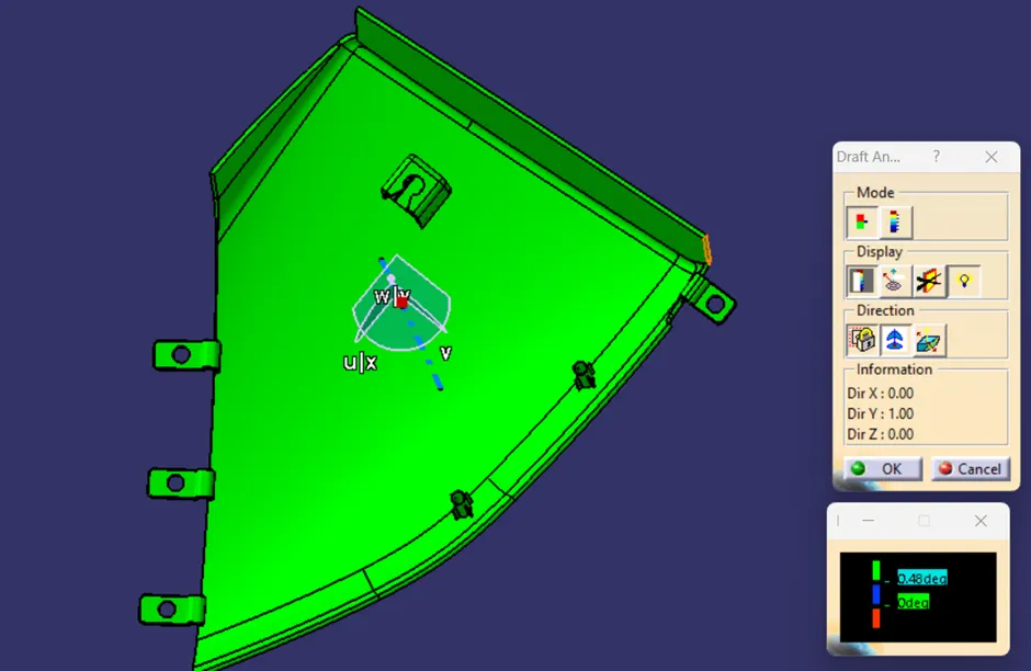
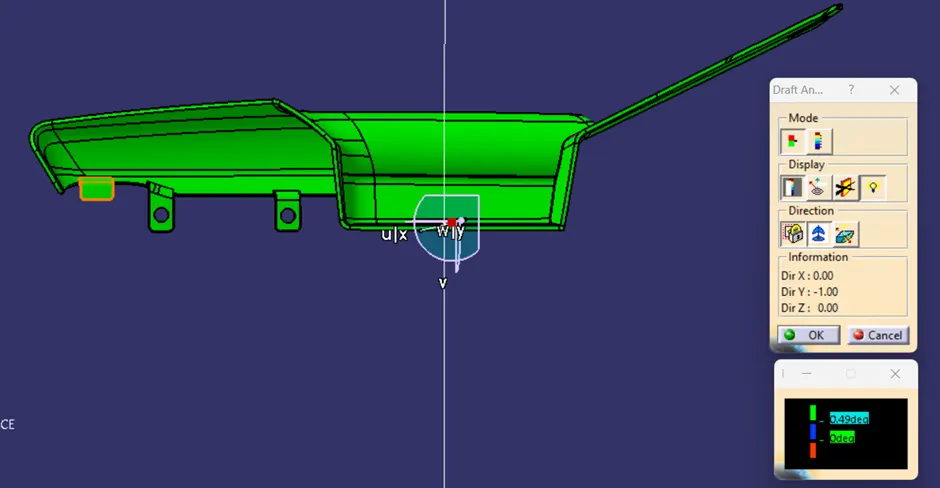
6. Draft analyses of each component were performed to check the manufacturing feasibility.
There are four main components for the given door trim.
<!-- [if !supportLists]-->1. <!--[endif]-->LOWER SUBSTRATE
<!-- [if !supportLists]-->2. <!--[endif]-->BOTTLE HOLDER
<!-- [if !supportLists]-->3. <!--[endif]-->MAP POCKET
<!-- [if !supportLists]-->4. <!--[endif]-->ARM REST
<!-- [if !supportLists]-->1. <!--[endif]-->LOWER SUBSTRATE
The given Class A is checked for any irregularities and tooling axis is created along the Y direction as we can observe that almost all the surfaces are visible in that direction.
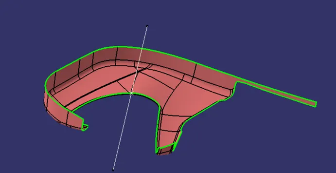
DRAFT ANALYSOIS OF CLASS A SURFACE
It is necessary that the tooling axis we created must clear the all the surfaces in the draft analysis. Unless and until we cannot proceed further. So, I checked the draft analysis of class A surface along the tolling axis as below.
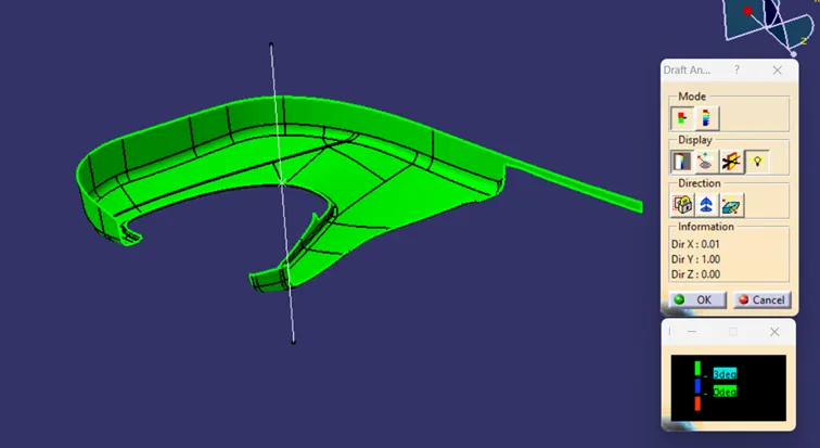
As we see whole surface is green then the tooling axis created is correct and the part will be manufacturable along that direction.
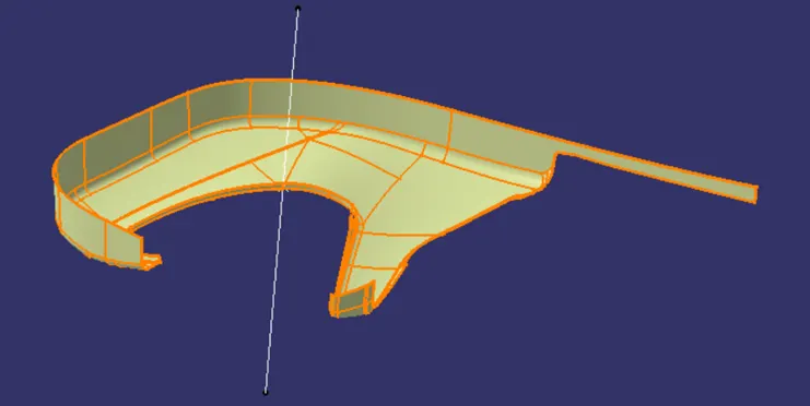
CREATION OF CLASS B SURFACE
Class A surface is offset by 2.5 mm to create the class B surface. The surfaces which aren’t get offset properly they are created using commands like extract, untrim, extrapolate, trim and using fillets.
The value for offset is measured from the master section provided.
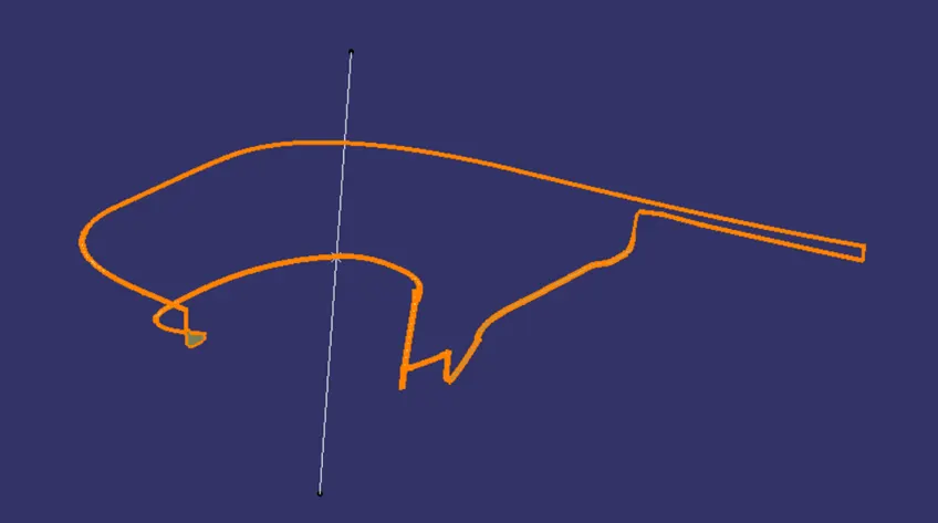
CREATION OF CLASS C SURFACE
Class C surface is created by sweeping the class A boundary at 87 degrees inside to surface.
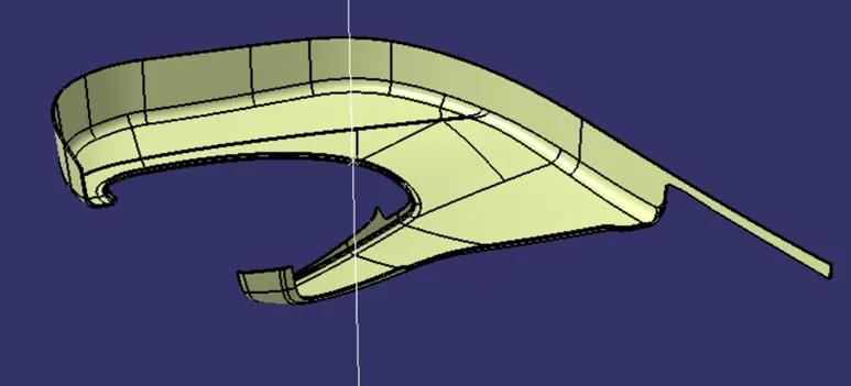
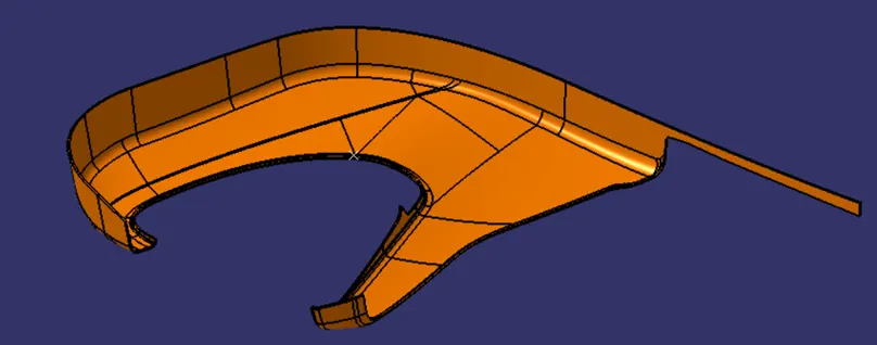
All these three surfaces are joined and trimmed with each other to get a closed surface body, to which later I converted into solid using closed surface command.
<!-- [if !supportLists]-->2. <!--[endif]-->BOTTLE HOLDER
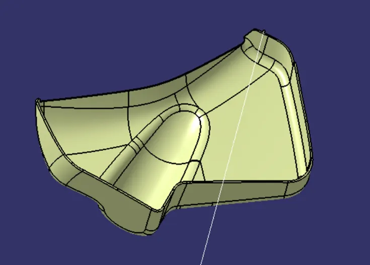
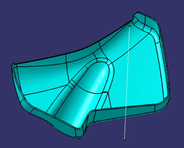
The given Class A is checked for any irregularities and tooling axis is created along the Y direction as we can observe that almost all the surfaces are visible in that direction.
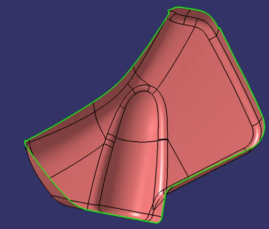
DRAFT ANALYSOIS OF CLASS A SURFACE
It is necessary that the tooling axis we created must clear the all the surfaces in the draft analysis. Unless and until we cannot proceed further. So, I checked the draft analysis of class A surface along the tolling axis as below.
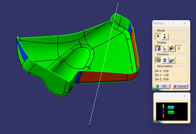
As we see some surfaces are not getting cleared in direction of tooling axis, we created so I tried to create another tooling axis using bisecting methods but all surfaces are not getting with that axis also. That why we considered it as class A problem and need to informed to the styling team for modification.
CREATION OF CLASS B SURFACE
Class A surface is offset by 2.5 mm to create the class B surface. The surfaces which aren’t get offset properly they are created using commands like extract, untrim, extrapolate, trim and using fillets.
The value for offset is measured from the master section provided.
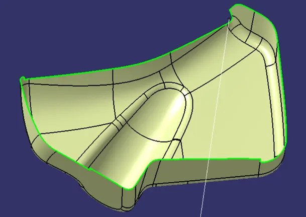
CREATION OF CLASS C SURFACE
Class C surface is created by sweeping the class A boundary at 87 degrees outside to surface.
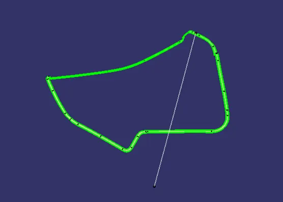
All these three surfaces are joined and trimmed with each other to get a closed surface body, to which later I converted into solid using closed surface command.
MAP POCKET
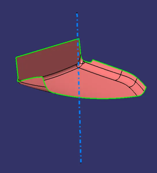
The given Class A is checked for any irregularities and tooling axis is created along the Y direction as we can observe that almost all the surfaces are visible in that direction.
DRAFT ANALYSOIS OF CLASS A SURFACE
It is necessary that the tooling axis we created must clear the all the surfaces in the draft analysis. Unless and until we cannot proceed further. So, I checked the draft analysis of class A surface along the tolling axis as below.
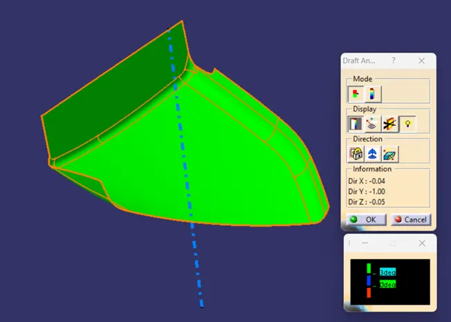
As we see whole surface is green then the tooling axis created is correct and the part will be manufacturable along that direction.
CREATION OF CLASS B SURFACE
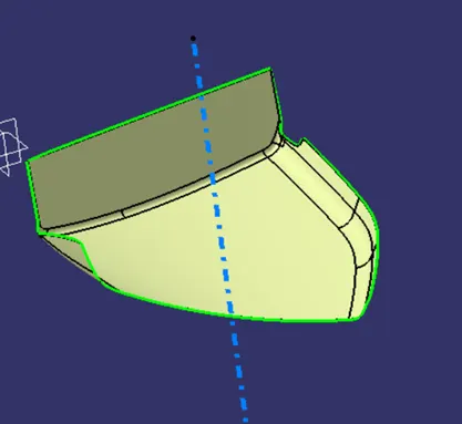
Class A surface is offset by 2.5 mm to create the class B surface. The surfaces which aren’t get offset properly they are created using multi section command.
The value for offset is measured from the master section provided.
CREATION OF CLASS C SURFACE
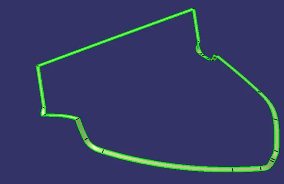
Class C surface is created by sweeping the class A boundary at 87 degrees inside to surface.
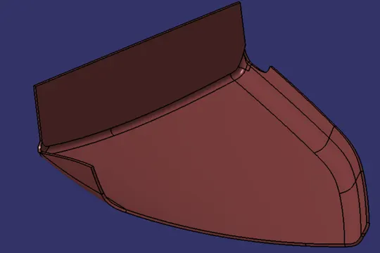
All these three surfaces are joined and trimmed with each other to get a closed surface body, to which later I converted into solid using closed surface command
<!-- [if !supportLists]-->3. ARM REST
The given Class A is checked for any irregularities and I found one. We need to inform these issues with the styling team.
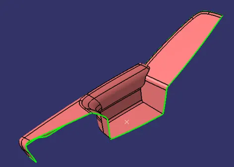
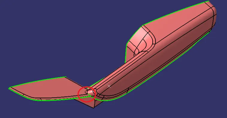
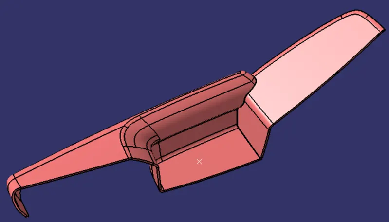
I have resolved this problem by extracting, extrapolating them and trimming with each other to get proper class A surface as below.
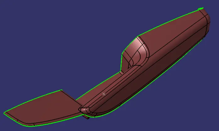
Tooling axis is created along the Y direction as we can observe that most all the surfaces are visible in that direction.
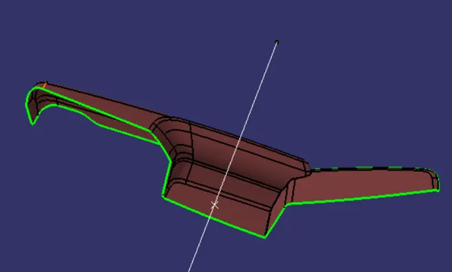
DRAFT ANALYSOIS OF CLASS A SURFACE
It is necessary that the tooling axis we created must clear the all the surfaces in the draft analysis. Unless and until we cannot proceed further. So, I checked the draft analysis of class A surface along the tolling axis as below.
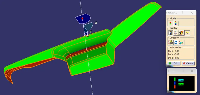
As we see some surfaces are not getting cleared in direction of tooling axis, we created so I tried to create another tooling axis using bisecting methods but all surfaces are not getting with that axis also.
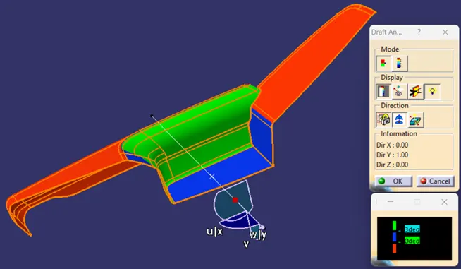
On careful observation we can see that this part is having kind of depression at mid portion that why it won’t be manufacturable with only direction. It will need two side cores which will move in Y directions. This will increase the cost of tool manufacturing eventually the cost of product. That why we need to informed about to the styling team for modification of class A surface.
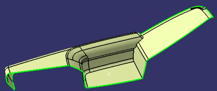
CREATION OF CLASS B SURFACE
Class A surface is offset by 2.5 mm to create the class B surface. The surfaces which aren’t get offset properly they are created using multi section command.
The value for offset is measured from the master section provided.
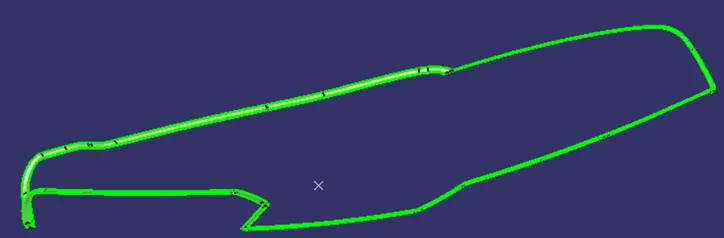
CREATION OF CLASS C SURFACE
Class C surface is created by sweeping the class A boundary at 87 degrees inside to surface.
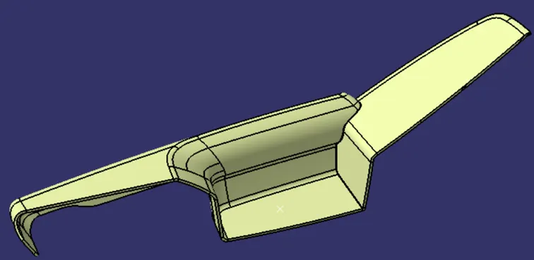
All these three surfaces are joined and trimmed with each other to get a closed surface body, to which later I converted into solid using closed surface command
CREATION OF ENGGINEERING FEATURES
<!-- [if !supportLists]-->1. <!--[endif]-->HEAT STAKES
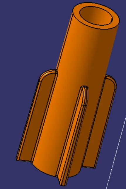
Heat stakes are used in thermoplastics to assemble two parts together by locally heating and cooling the plastic material and allowing it to reform itself and act as a joint for the two materials.
We have placed 12 heat stakes (10 on lower substrate and 2 on map pocket) in the model based on the reference points created by estimation and according to design rules.
One of the important factors to be considered while designing the heat skates is the height of the heat skates. It should always be less than the height of the locators.
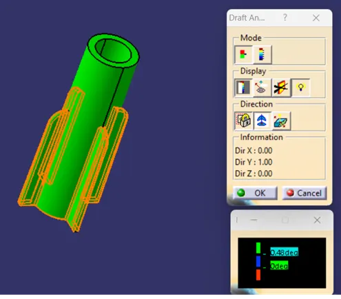
The wall thickness of heat stake is maintained lower than 1 mm which is less than 40% of the part thickness and also 0.5-degree draft is provided to all faces along the main tooling axis as per the design rules.
After creation of heat stake, I have copied and translated them to required position as per the master section requirements.
DRAFT ANALYSIS OF HEAT STAKE ALONG MAIN TOOLING AXIS
<!-- [if !supportLists]-->2. <!--[endif]-->FLANGES
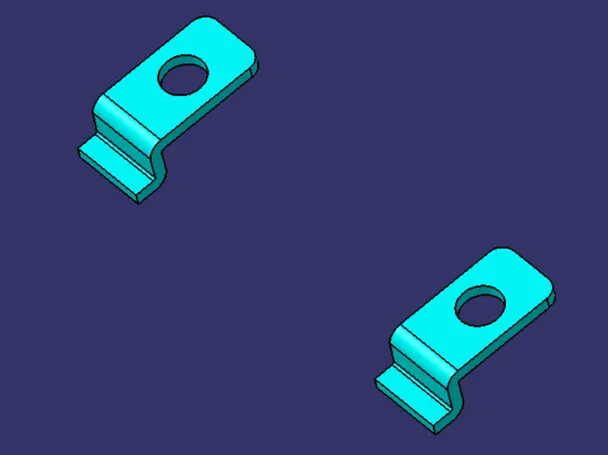
From master section we get the idea of flanges. I have created flanges by using same point I used for heat stakes and considering counterpart (heat stakes) position.
Flanges are having thickness of 2.5mm as provided in master section and also to maintain the even thickness throughout the part. Also, they are provided with draft of 0.5 degrees along the tooling direction of respective parts.
<!-- [if !supportLists]-->3. <!--[endif]-->DOG HOUSE
- Dog houses are designed to avoid SINK MARK created on the CLASS-A surface by screw bosses and to solve the length issues when giving screw bosses which need to be assembled to other components.
- It is also useful when perpendicular screw bosses are required on the part to the tooling direction.
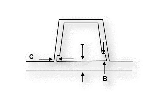
- C thickness should be 40% of the main wall thickness T
- Height of B should be 3-6 mm
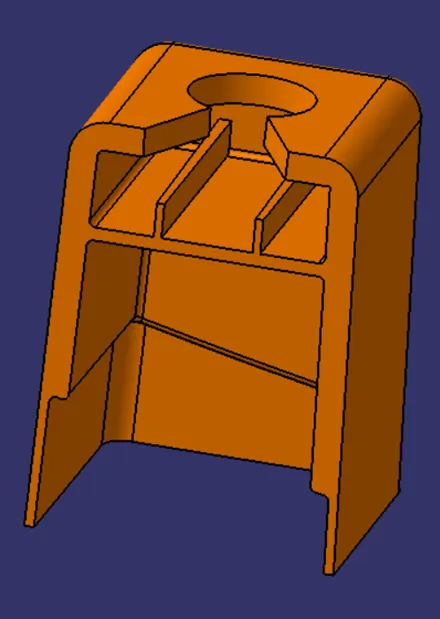
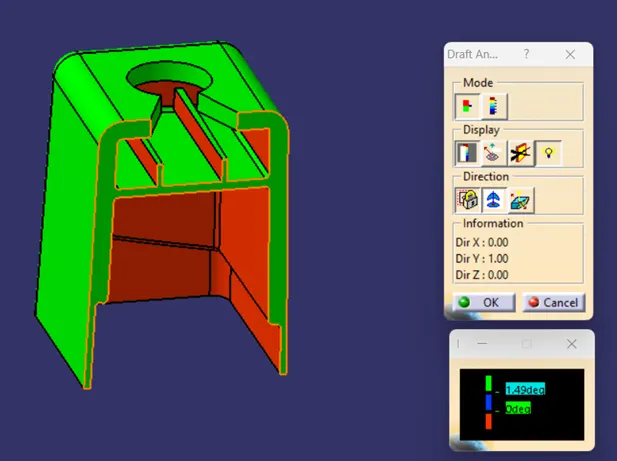
DRAFT ANALYSIS OF DOG HOUSE ALONG MAIN TOOLING AXIS
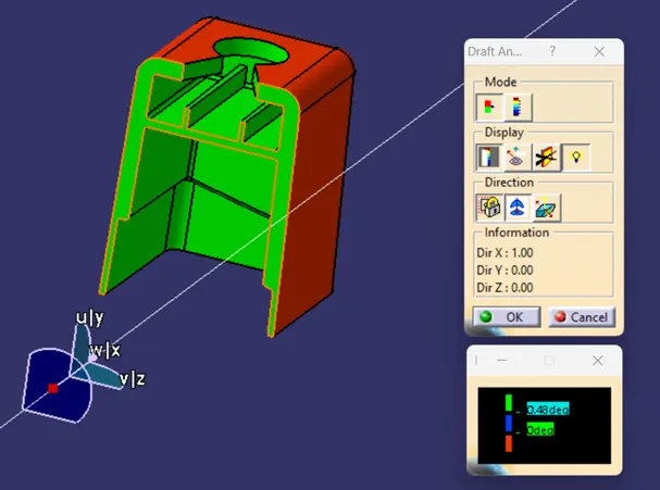
DRAFT ANALYSIS OF DOG HOUSE ALONG SIDE CORE AXIS
DRAFT ANALYSIS OF FINAL PARTS
-
- <!-- [if !supportLists]--> <!--[endif]-->LOWER SUBSTRATE
<!-- [if !supportLists]-->2. <!--[endif]-->BOTTLE HOLDER
<!-- [if !supportLists]-->3. <!--[endif]-->MAP POCKET
<!-- [if !supportLists]-->4. <!--[endif]-->ARM REST
FINAL DOOR TRIM
CONCLUSION: - Design of Door trim through Master Section Development and draft analysis has been successfully done, considering the design rules as mentioned in the given data.