Week 9 - Challenge 1 - Base Bracket Design
AIM: Create the Base Bracket Plastic component through the given Class-A surface. To begin with, the tooling axis for the given Class A Surface should be created meeting the requirements of the draft angle and at the end perform the Draft analysis on the model.
Thickness of the plastic part is 2.5 mm.
INPUTS:
Class A surface
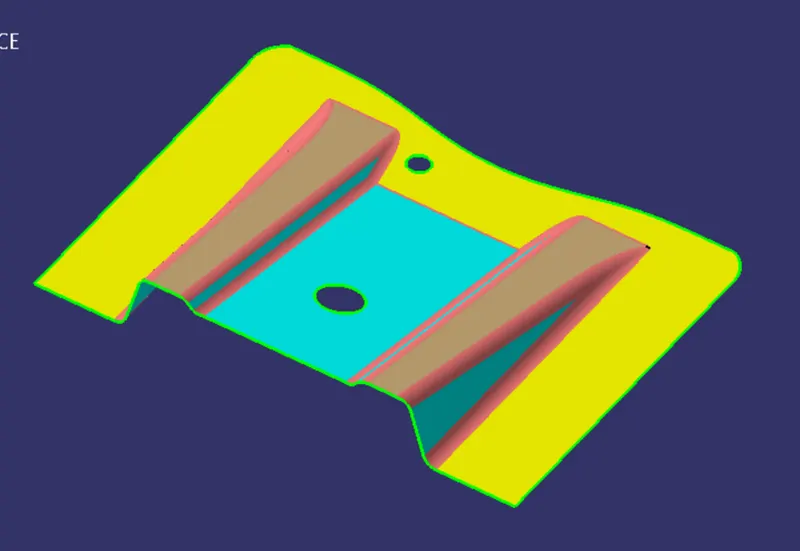
Class A is the concept surface created by the free-hand sketchers. The finalized sketch is then converted to 2D surface using software like Alias.
Creation of tooling axis:
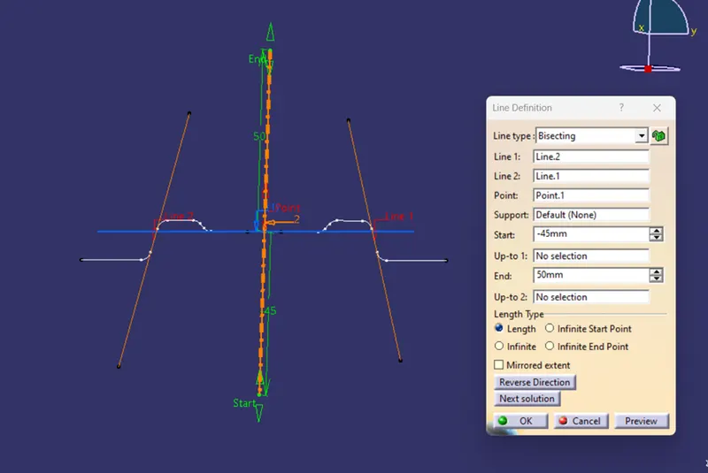
Tooling axis or moulding axis is the direction of opening of core and cavity of the mould. Tooling axis is created using bisecting method.
BISECTING METHOD
First observe the part geometry to understand the best direction for tooling axis. In this case two hole are present on the surface in XY plane so Z will be the best tooling direction.
After selection of the direction, dummy tooling axis is created by intersecting the surface with the YZ plane.
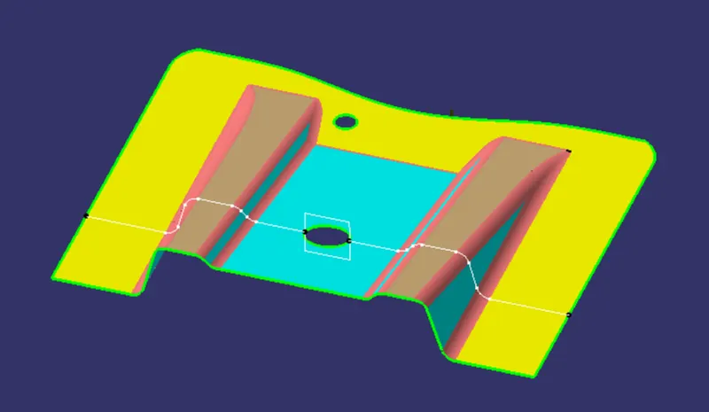
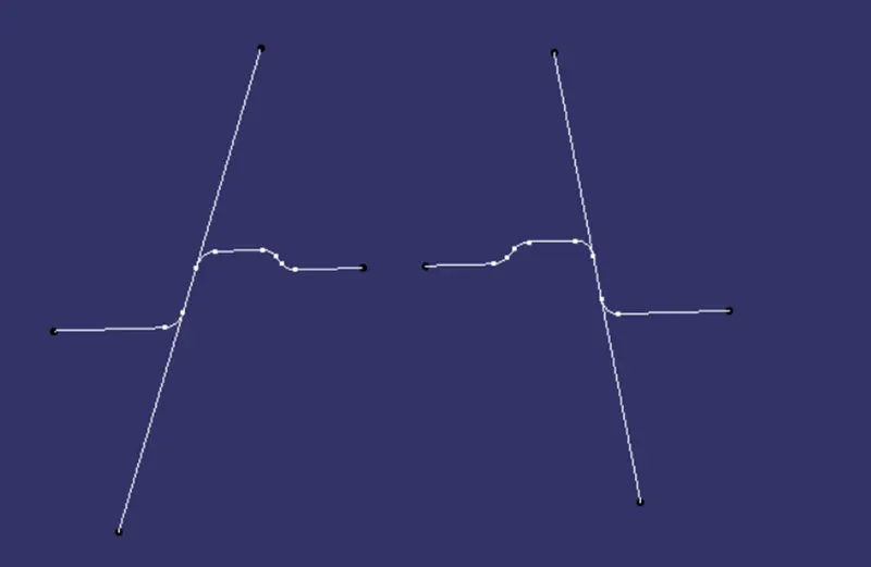
Create the Tooling axis by bisecting the dummy axes.
TREE STRUCTURE:
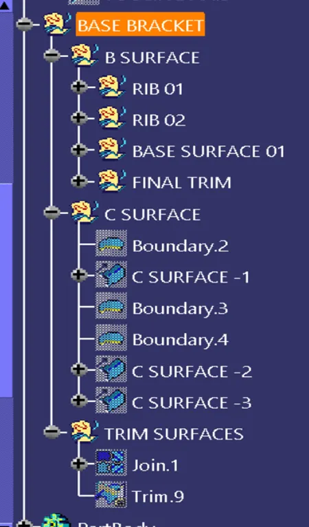
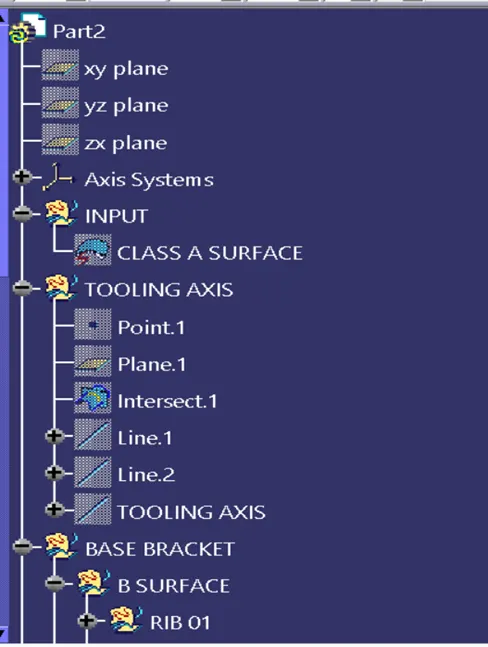
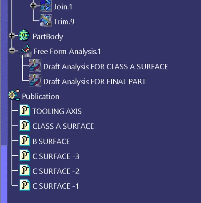
DRAFT ANALYSIS:
Draft analysis is need to be carried out to find that the tooling direction chosen is correct and the designed part is manufacturable with it or not.
DRAFT ANALYSIS OF CLASS A SURFACE:
First thing to do is to pick the compass from the draft analysis tool bar and alligned it with the tolling axis. Once did that lock the movement of the compass by clicking on lock tool adjacent to compass.
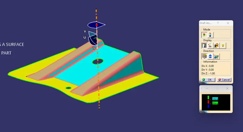
After that click anywhere on the surface
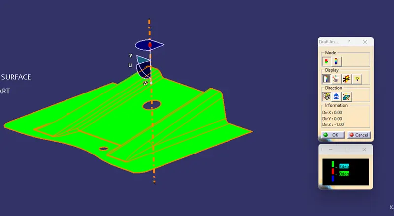
If the part is shown in green colour as above it means the part is manufacturable with the chosen tooling direction.
DRAFT ANALYSIS OF FINAL PART:
After the creation of class B and class C surface and intersecting them with other we get the hollow surface with the required thickness. Convert this surface to part body using close surface command from part workbench.
Once this is done part is ready. Then we can process with the draft analysis on it.
Select the compass from draft analysis tool bar and placed it on tooling axis. After placing lock it, as below.
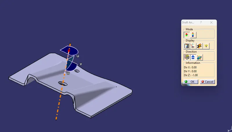
Click on the part surface.
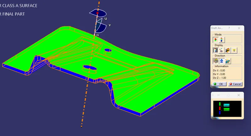
If the part is shown in green colour as above it means the part is manufacturable with the chosen tooling direction.
If not then proceed with corrective actions by changing the draft angle or draft direction or modifying the tooling axis orientation.
ISOMETRIV VIEW
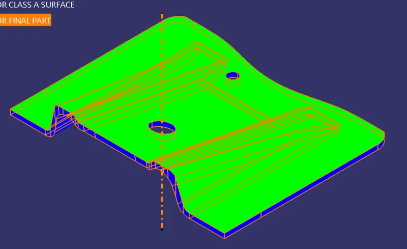
FRONT VIEW
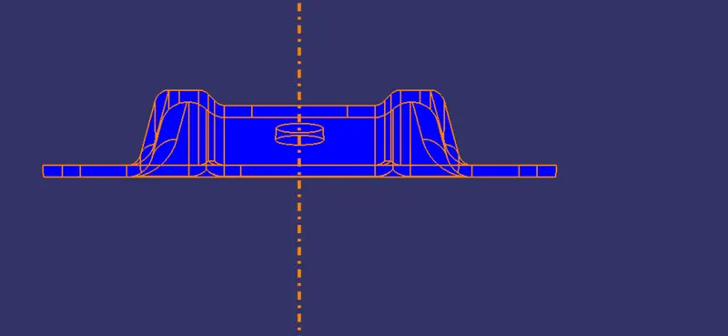
SIDE VIEW
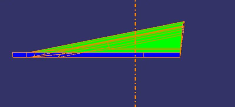
BACK VIEW
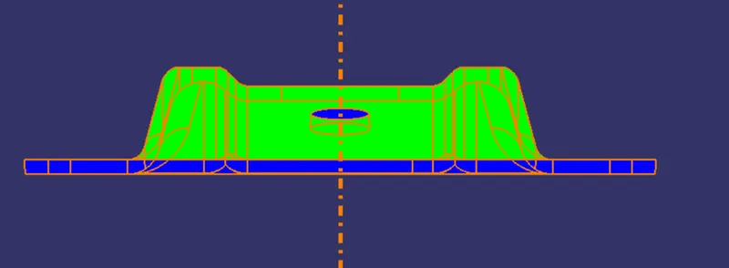
TOP VIEW
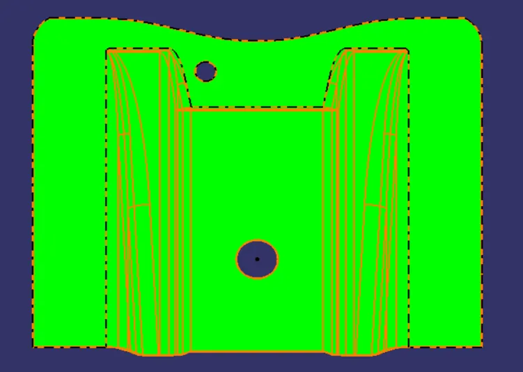
CONCLUSION:
The Design of Plastic Component - Base Bracket from Class A is completed using concepts of Draft angle, Draft Analysis, Tooling Axis, Class B and Class C creation and converting Closed surface to a solid part.