Week 12- Final project
AIM:
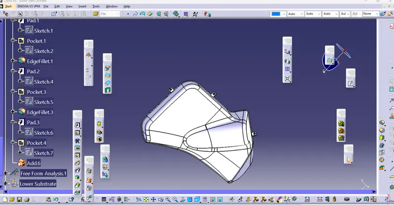
To develop the Door Trim panel
Steps involved in developing a door trim panel:
- Create the class A surface. This is the outer surface of the door trim panel, and it is what will be visible to the driver and passengers. The class A surface should be smooth and free of defects.
- Add the nominal thickness. This is the thickness of the door trim panel, and it is important for determining the strength and stiffness of the panel. The nominal thickness should be consistent throughout the panel.
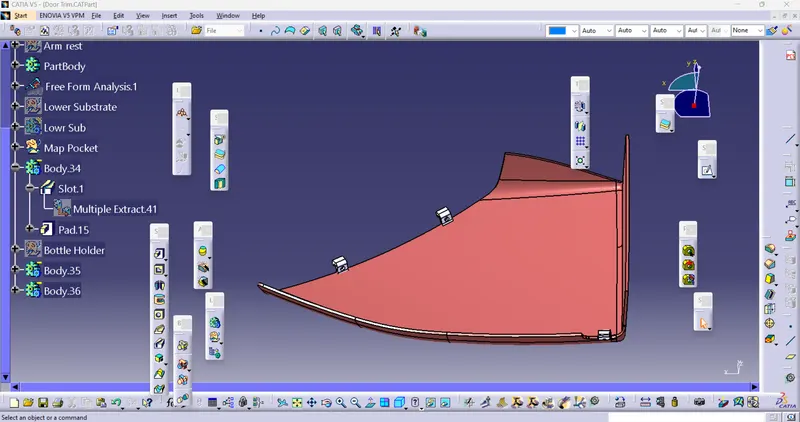
- Add the attachment features. These are the features that will allow the door trim panel to be attached to the door. The attachment features can include tabs, slots, and screws.
- Design the ribs and bosses. Ribs and bosses are structural features that help to strengthen the door trim panel. The ribs and bosses should be designed to provide the necessary strength without adding too much weight to the panel.
- Create the CAD model. The CAD model is a digital representation of the door trim panel. The CAD model can be used to simulate the assembly of the panel and to check for fit and clearance.
- Generate the tooling data. The tooling data is used to create the molds that will be used to manufacture the door trim panel. The tooling data must be accurate in order to ensure that the panels are manufactured correctly.
SOFTWARE USED: CATIA
Let us look at how we have designed
INPUT:
CAD DATA is downloaded and Opened with CATIA.
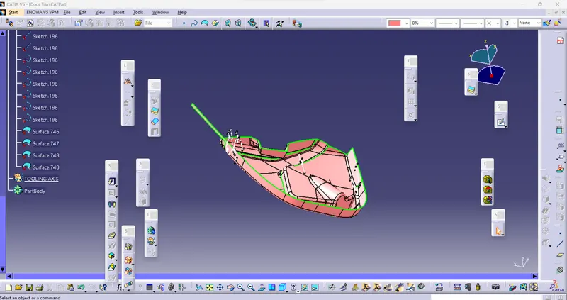
1- Armrest Part:
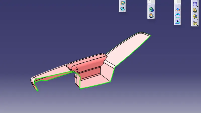
TOOLING AXIS:
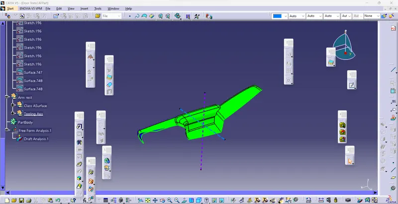
The tooling axis is defined as such all the features of the part can be manufactured easily. Bisecting method, point, and direction are methods used here.
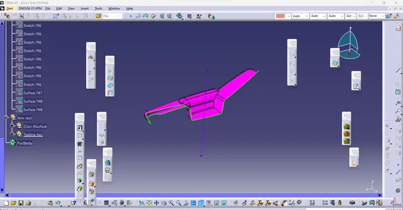
Main Tooling Axis and Side Tooling Axis are created in such way to provide drafting.
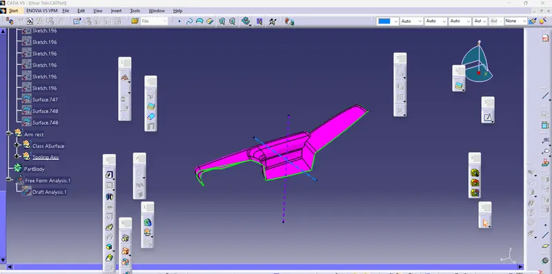
DRAFT ANALYSIS OF CLASS A SURFACE
Green color - above 3 degrees positive draft
Red color -between 3 and 0
blue color- below 0 degree
The view changed to material mode
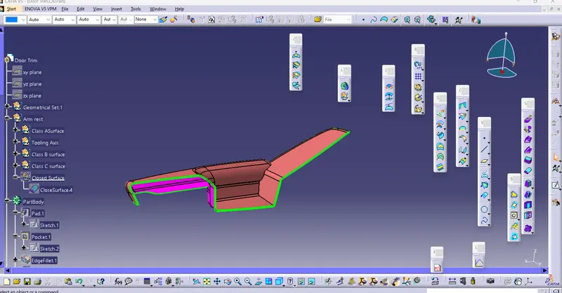
Class B Surface:
B SURFACE is created by Offsetting the class-A surface to 2.5mm inward direction.
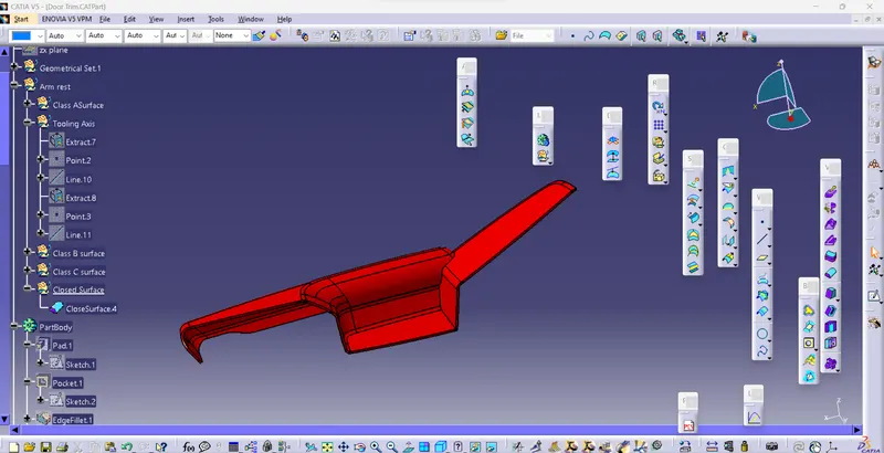
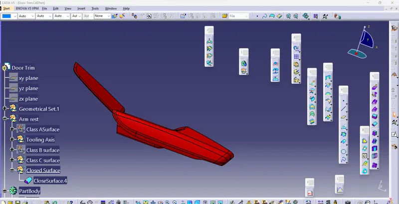
CLASS C SURFACE and PART BODY:
The surface that joins class-A and class-B surfaces are class-C surfaces.
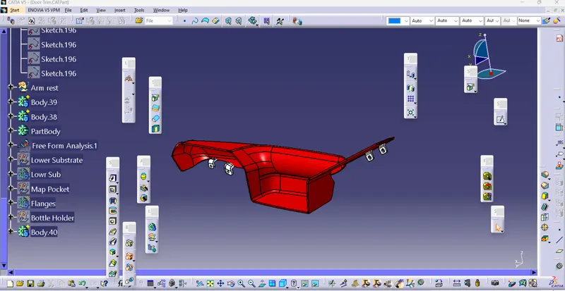
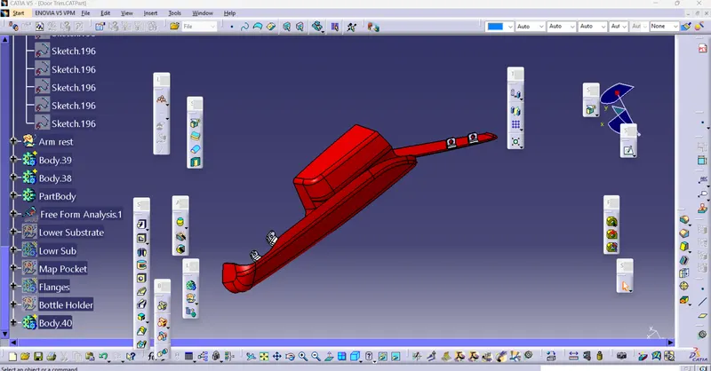
Flanges:
2. Lower Substrate:
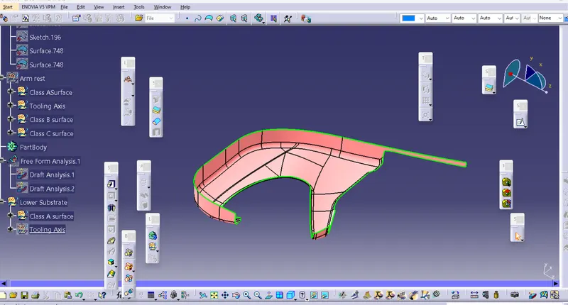
TOOLING AXIS:
The tooling axis is defined as such all the features of the part can be manufactured easily. Bisecting method, point, and direction are methods used here.
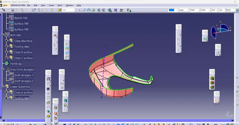
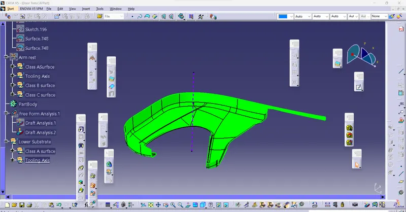
DRAFT ANALYSIS OF CLASS A SURFACE
Green color - above 3 degrees positive draft
Red color -between 3 and 0
blue color- below 0 degree
The view changed to material mode
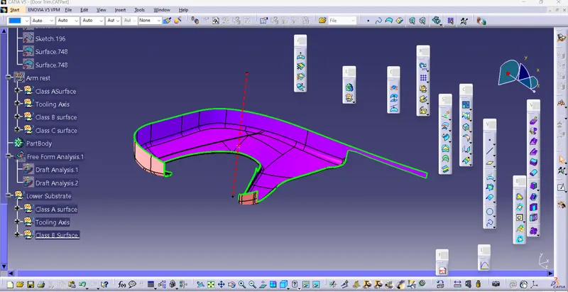
CLASS B SURFACE
B SURFACE is created by Offsetting the class-A surface to 2.5mm inward direction.
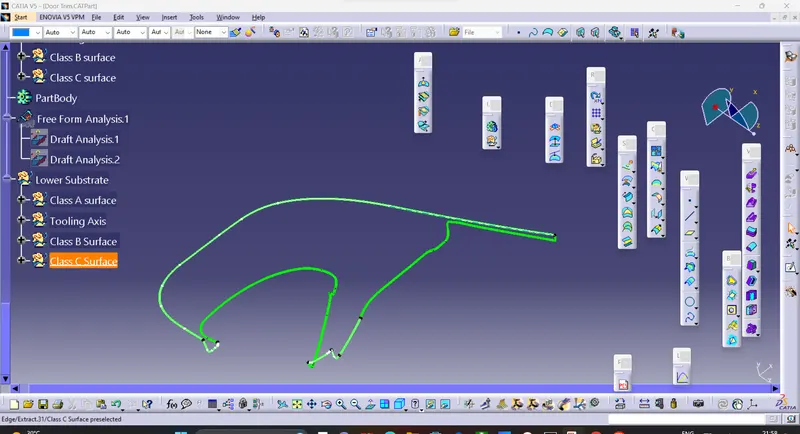
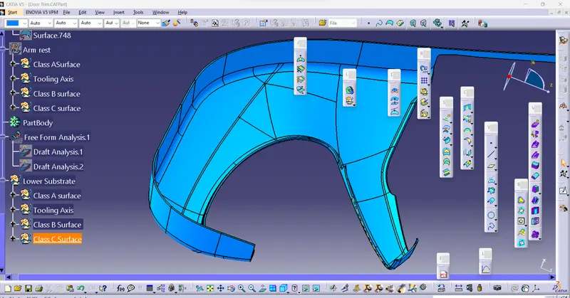
CLASS C SURFACE:
The surface that joins class-A and class-B surfaces are class-C surfaces.
PART BODY:
To create the solid part body from the closed surface, I used the closed surface command in the part workbench.
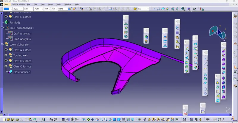
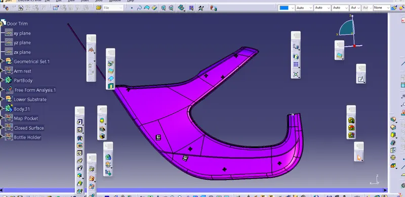
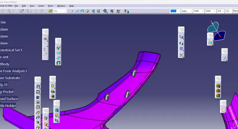
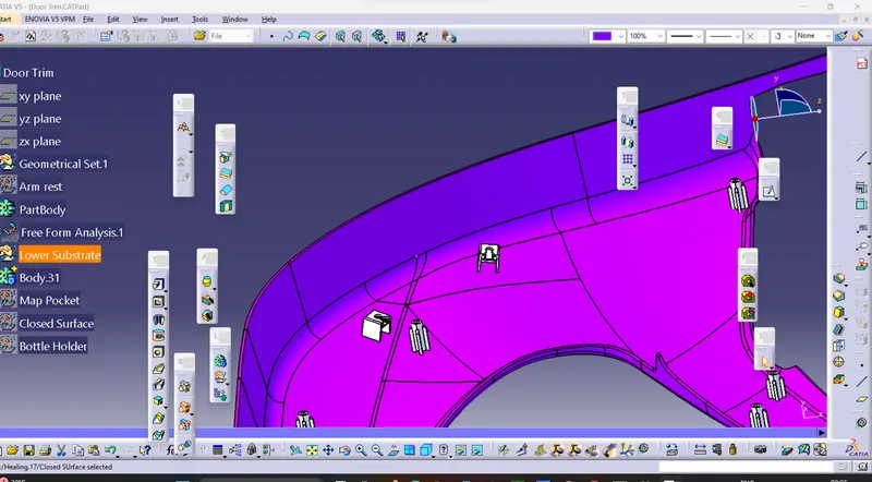
Ribs & Screw Boss and Dog House:
3. Map Pocket:
Class A Surface:
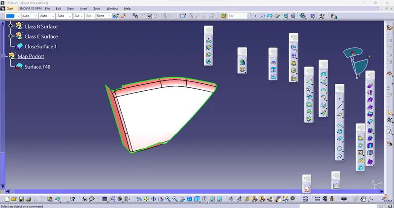
Tooling Axis:
The tooling axis is defined as such all the features of the part can be manufactured easily. Bisecting method, point, and direction are methods used here.
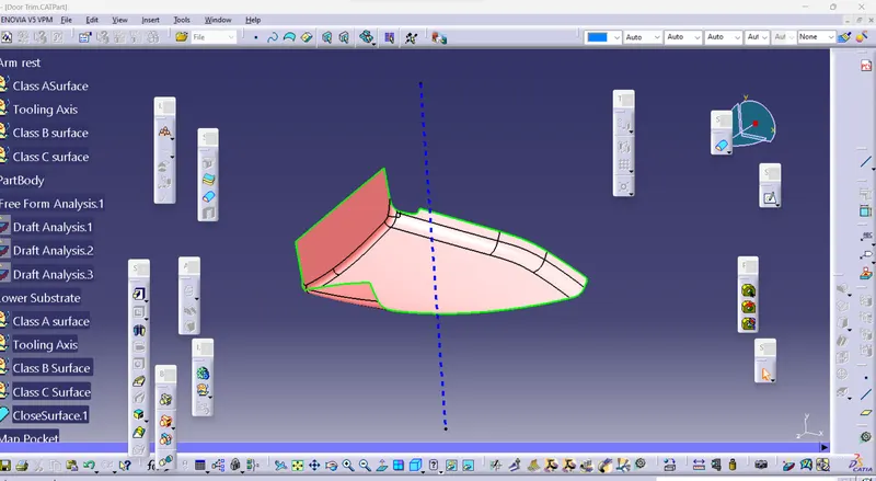
DRAFT ANALYSIS OF CLASS A SURFACE
Green color - above 3 degrees positive draft
Red color -between 3 and 0
blue color- below 0 degree
The view changed to material mode
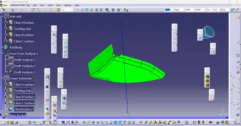
CLASS B SURFACE
B SURFACE is created by Offsetting the class-A surface to a 2.5mm inward direction.
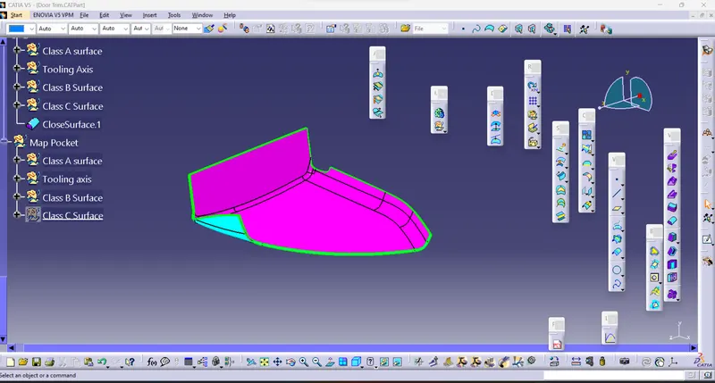
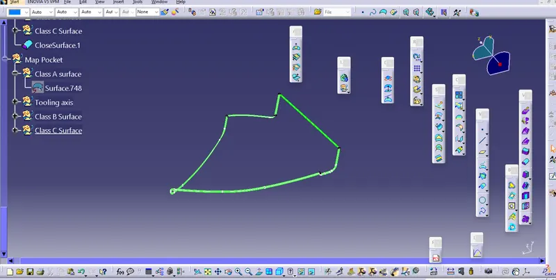
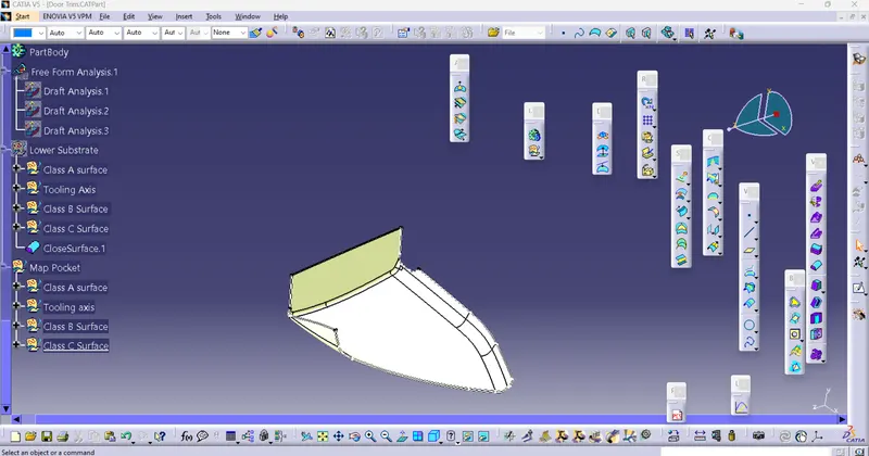
CLASS C SURFACE:
The surface that joins class-A and class-B surfaces are class-C surfaces.
PART BODY:
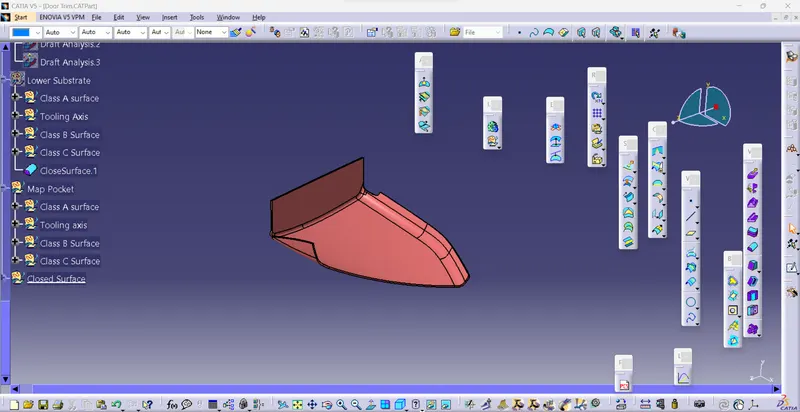
To create the solid part body from the closed surface, I used the closed surface command in the part workbench.
Flanges with counter holes:
BOTTLE HOLDER:
Class A Surface:
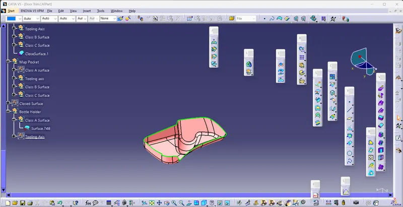
Tooling Axis:
The tooling axis is defined as such all the features of the part can be manufactured easily. Bisecting method, point, and direction are methods used here.
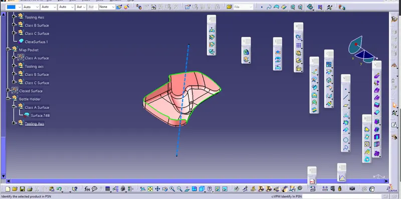
DRAFT ANALYSIS OF CLASS A SURFACE
Green color - above 3 degrees positive draft
Red color -between 3 and 0
blue color- below 0 degree
The view changed to material mode
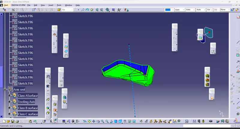
CLASS B SURFACE
B SURFACE is created by Offsetting the class-A surface to a 2.5mm outward direction.
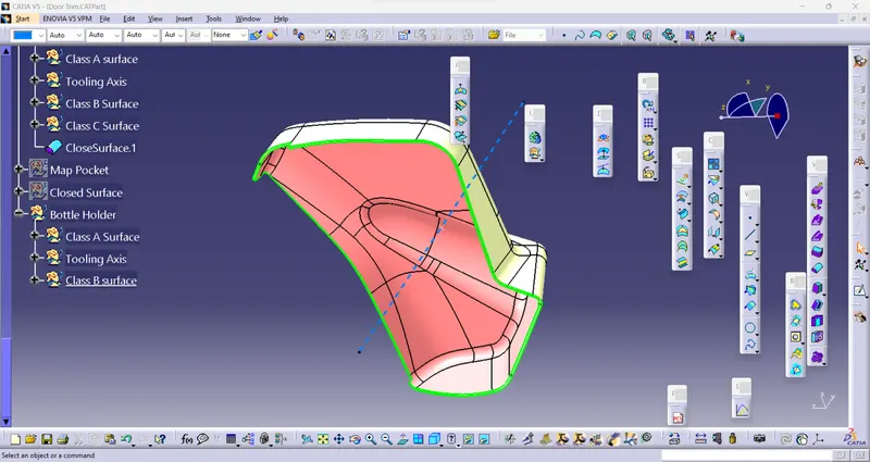
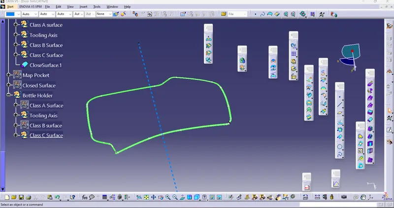
CLASS C SURFACE:
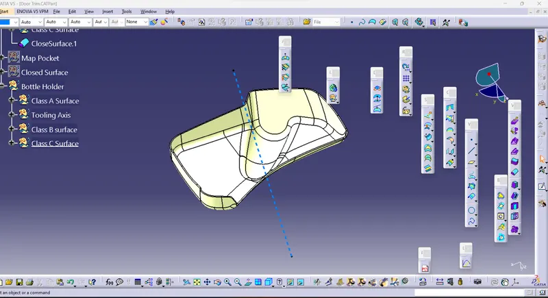
The surface that joins class-A and class-B surfaces are class-C surfaces.
PART BODY:
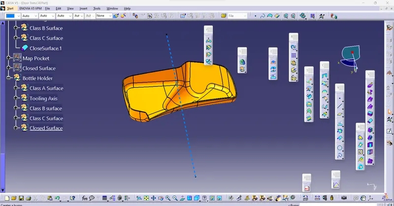
To create the solid part body from the closed surface, I used the closed surface command in the part workbench.
Flanges:
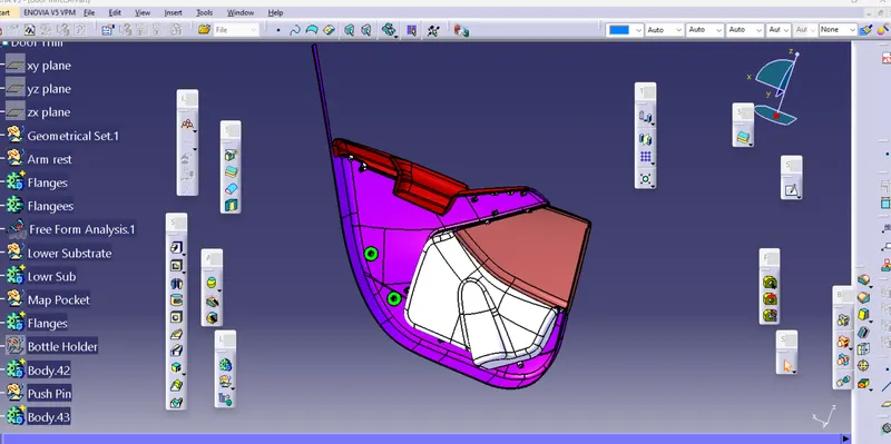
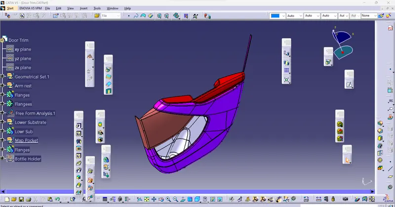
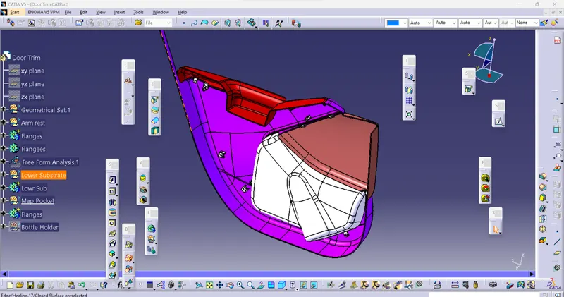
Final Model:
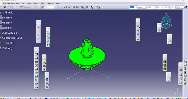
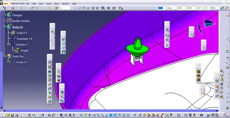
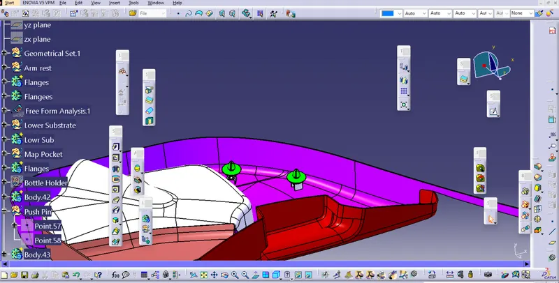
Push Pin: