Week 12- Final project
Aim:
To create a CAD model (Door Trim Panel) with attachment features considering the given inputs, design rules and following the OEM standards.
Procedure:
The first step to follow in this project is to extract the CLASS-A surface (individually for each component) of the Door Trim Panel and divide these surfaces into different Geometrical sets as follows.
- Arm Rest
- Lower Substrate
- Map Pocket
- Bottle holder
Methodology:
- CLASS-A
- Creation of different Geometrical sets for each component such as Arm Rest,Lower Substrate,Map Pocker, Bottle holder
- Tooling Axis / Side Core Axis Creation
- Creation of CLASS-B Surface
- Creation of CLASS-C Surface
- Joining of CLASS-A, B & C Surface
- Performing a check for boundaries
- Forming a Solid Body
- Attachment features creation
- Performing Draft Analysis
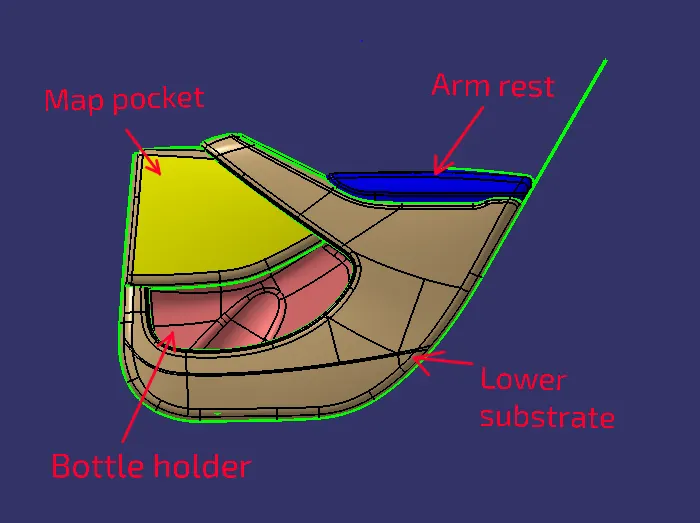
1.Arm Rest:
CLASS-A :
Initially, we need to extract the CLASS-A surface for the Arm Rest from the given input.
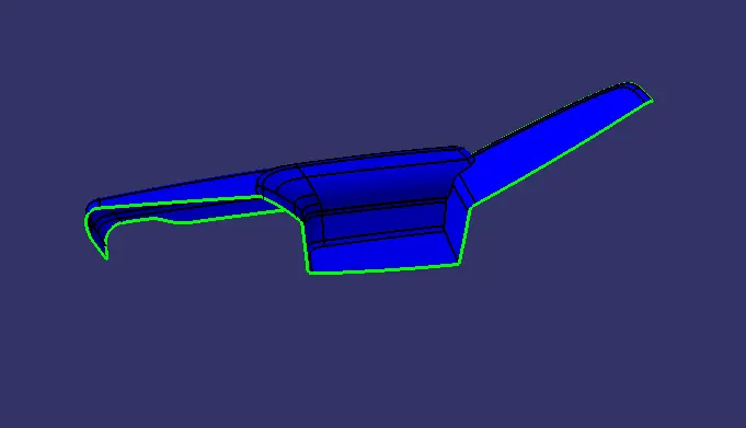
Tooling Axis:
A tooling axis needs to be created in a direction from which it can capture most parts/features of the component.
In this case, we need to create the tooling axis in z-direction, we first need to create a point and using this point create a line giving direction in the Z-axis. This line will give us the Tooling Axis.
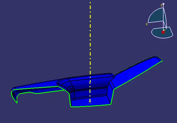
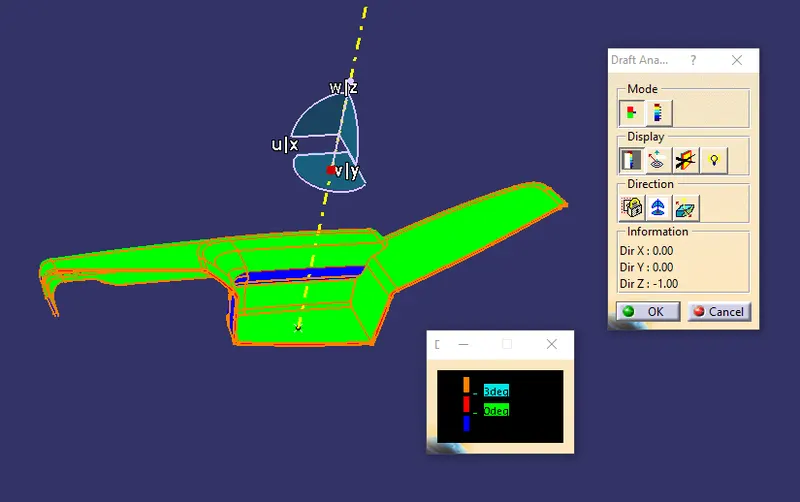
Draft Analysis on CLASS-A surface:
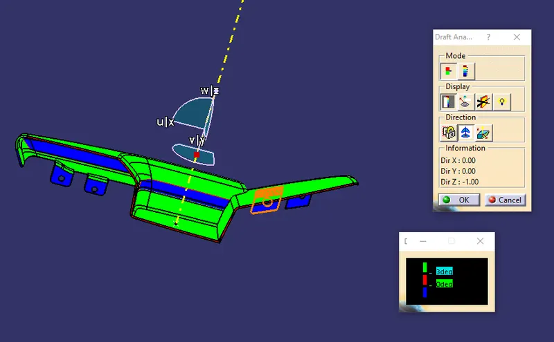
To ensure if the Tooling Axis we created is proper, we need to inspect the CLASS-A surface by performing a Draft Analysis on it.
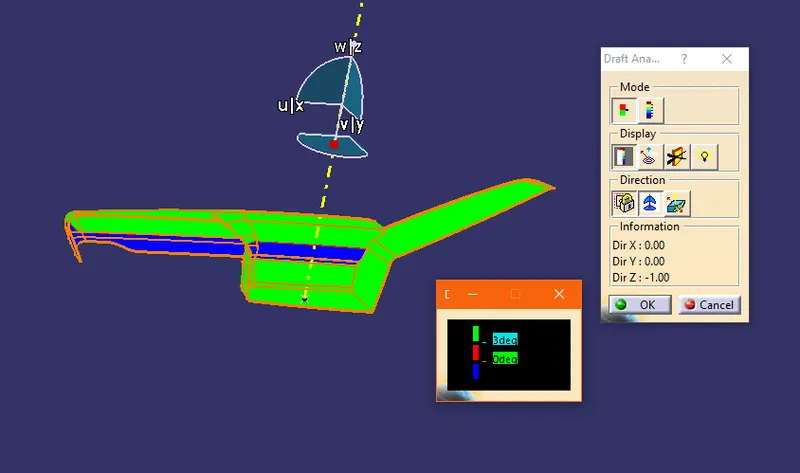
CLASS-B surface:
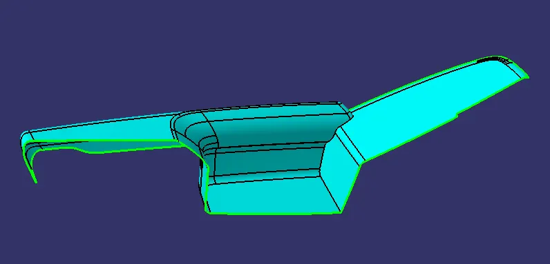
To create the CLASS-B surface, the CLASS-A surface is offset by 2.5mm (since the thickness of the component is 2.5mm). From the master sections which is given to us as input, we can measure the thickness of the component. At times few surfaces of the CLASS-B surfaces cannot be offset due to the change in the fillet region. These issues can be fixed by creating the surface manually in those portions. Since there are no issues on this surface we can proceed to the next step.
CLASS-C surface:
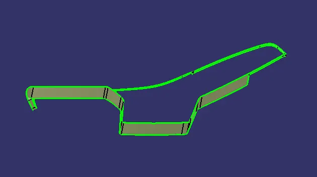
To create a CLASS C surface first extract the boundaries of the CLASS A surface.Now using the ‘sweep’ option create the C surface by sweeping the boundary of the CLASS-A surface at an angle of 3deg outwards to the tooling direction
Join all these sweep surfaces to form the final C surface.
Close surface :
To form a closed surface we first need to join the CLASS A surface with the CLASS C surface and then trim this joined surface with the CLASS B surface to get the final output.Check if there are any gaps after joining the surfaces by using the boundary option. If there will be any gaps after the joining of surfaces then these gaps need to be fixed to form a closed body
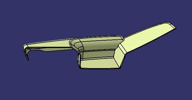
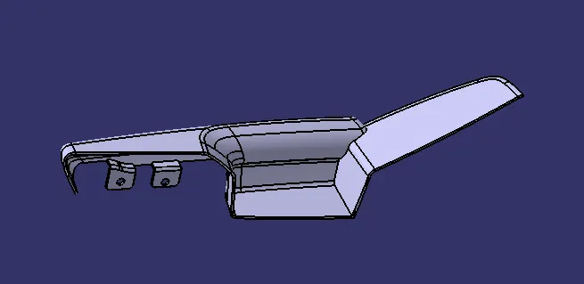
Using the “CLOSE SURFACE” option in PART WORKBENCH, a solid body from the closed surface can be formed.
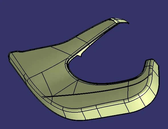
2.Lower Substrate
CLASS-A :
Initially, we need to extract the CLASS-A surface for the Lower Substrate from the given input.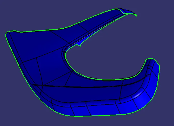
Tooling Axis:
A tooling axis needs to be created in a direction from which it can capture most parts/features of the component.
In this case, we need to create the tooling axis in y-direction, we first need to create a point and using this point create a line giving direction in the y-axis. This line will give us the Tooling Axis.
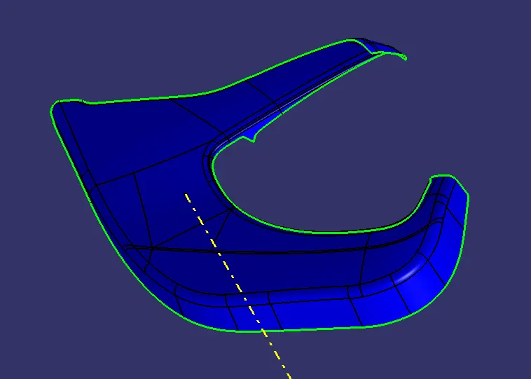
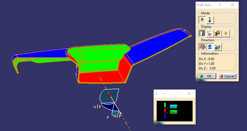
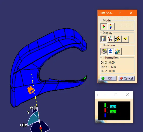
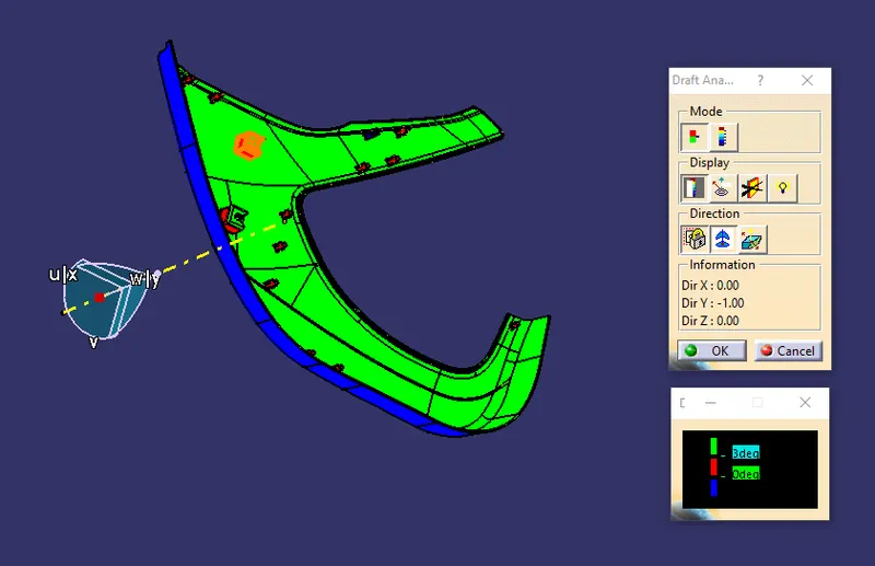
Draft Analysis on CLASS-A surface:
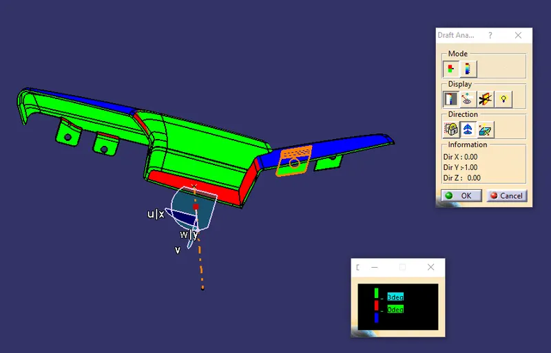
To ensure if the Tooling Axis we created is proper, we need to inspect the CLASS-A surface by performing a Draft Analysis on it.
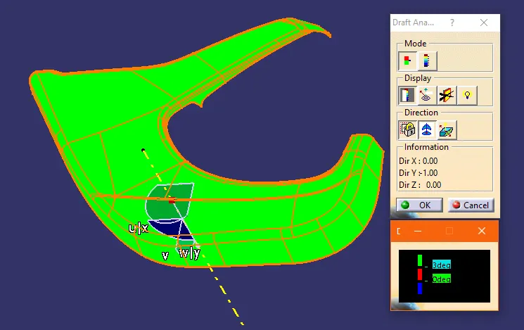
CLASS-B surface:
To create the CLASS-B surface, the CLASS-A surface is offset by 2.5mm (since the thickness of the component is 2.5mm). From the master sections which is given to us as input, we can measure the thickness of the component. At times few surfaces of the CLASS-B surfaces cannot be offset due to the change in the fillet region. These issues can be fixed by creating the surface manually in those portions. Since there are no issues on this surface we can proceed to the next step.
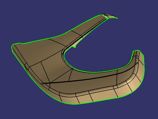
CLASS-C surface:
To create a CLASS C surface first extract the boundaries of the CLASS A surface.Now using the ‘sweep’ option create the C surface by sweeping the boundary of the CLASS-A surface at an angle of 3deg outwards to the tooling direction
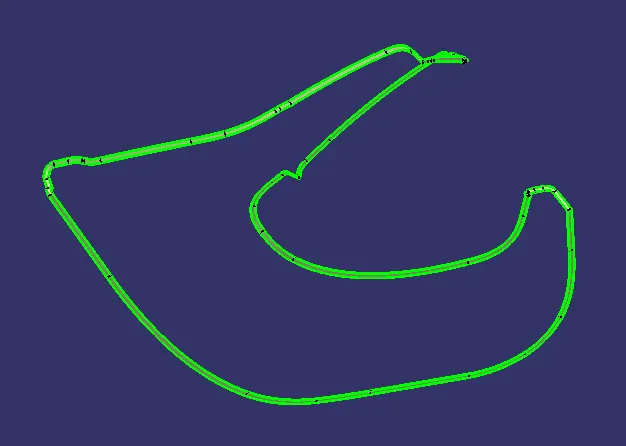
Join all these sweep surfaces to form the final C surface.
Close surface :
To form a closed surface we first need to join the CLASS A surface with the CLASS C surface and then trim this joined surface with the CLASS B surface to get the final output.Check if there are any gaps after joining the surfaces by using the boundary option. If there will be any gaps after the joining of surfaces then these gaps need to be fixed to form a closed body
Using the “CLOSE SURFACE” option in PART WORKBENCH, a solid body from the closed surface can be formed.
3.Map Pocket
CLASS-A :
Initially, we need to extract the CLASS-A surface for the Map pocket from the given input.
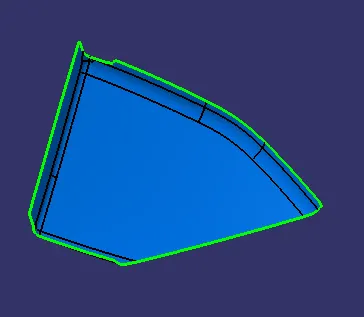
Tooling Axis:
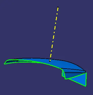
A tooling axis needs to be created in a direction from which it can capture most parts/features of the component.
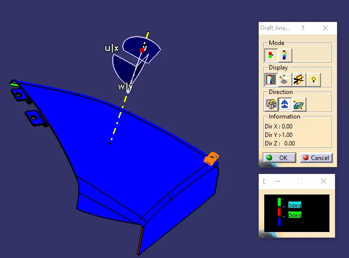
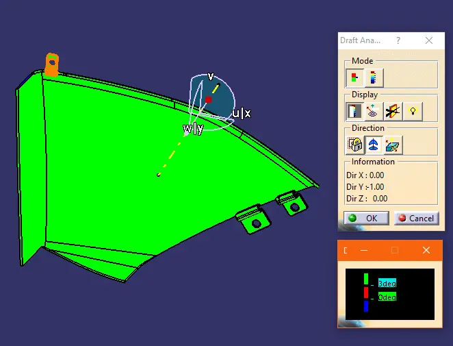
In this case, we need to create the tooling axis in y-direction, we first need to create a point and using this point create a line giving direction in the y-axis. This line will give us the Tooling Axis.
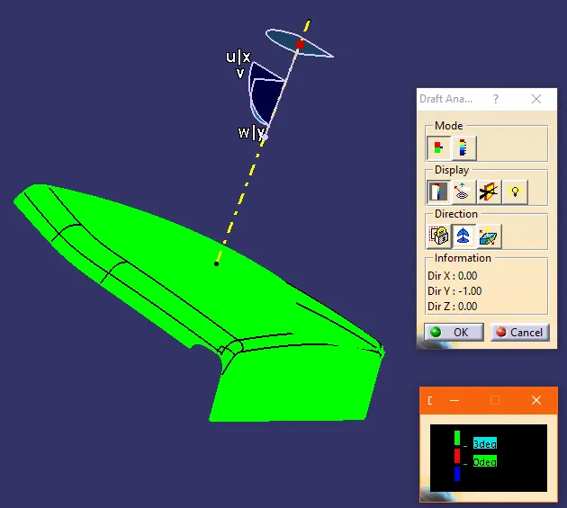
Draft Analysis on CLASS-A surface:
To ensure if the Tooling Axis we created is proper, we need to inspect the CLASS-A surface by performing a Draft Analysis on it.
CLASS-B surface:
To create the CLASS-B surface, the CLASS-A surface is offset by 2.5mm (since the thickness of the component is 2.5mm). From the master sections which is given to us as input, we can measure the thickness of the component. At times few surfaces of the CLASS-B surfaces cannot be offset due to the change in the fillet region. These issues can be fixed by creating the surface manually in those portions. Since there are no issues on this surface we can proceed to the next step.
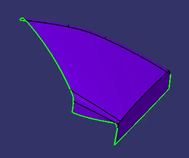
CLASS-C surface:
To create a CLASS C surface first extract the boundaries of the CLASS A surface.Now using the ‘sweep’ option create the C surface by sweeping the boundary of the CLASS-A surface at an angle of 3deg outwards to the tooling direction
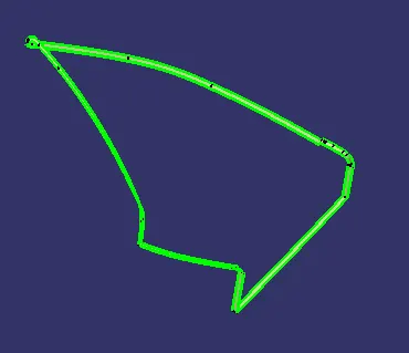
Join all these sweep surfaces to form the final C surface.
Close surface :
To form a closed surface we first need to join the CLASS A surface with the CLASS C surface and then trim this joined surface with the CLASS B surface to get the final output.Check if there are any gaps after joining the surfaces by using the boundary option. If there will be any gaps after the joining of surfaces then these gaps need to be fixed to form a closed body
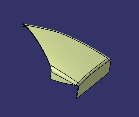
Using the “CLOSE SURFACE” option in PART WORKBENCH, a solid body from the closed surface can be formed.
4.BOTTLE HOLDER
CLASS-A :
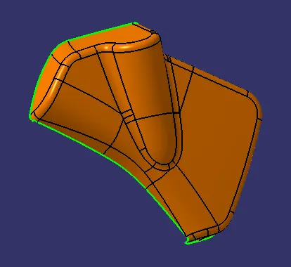
Initially, we need to extract the CLASS-A surface for the Bottle holder from the given input.
Tooling Axis:
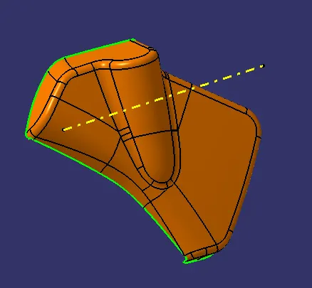
A tooling axis needs to be created in a direction from which it can capture most parts/features of the component.
In this case, we need to create the tooling axis in y-direction, we first need to create a point and using this point create a line giving direction in the y-axis. This line will give us the Tooling Axis.
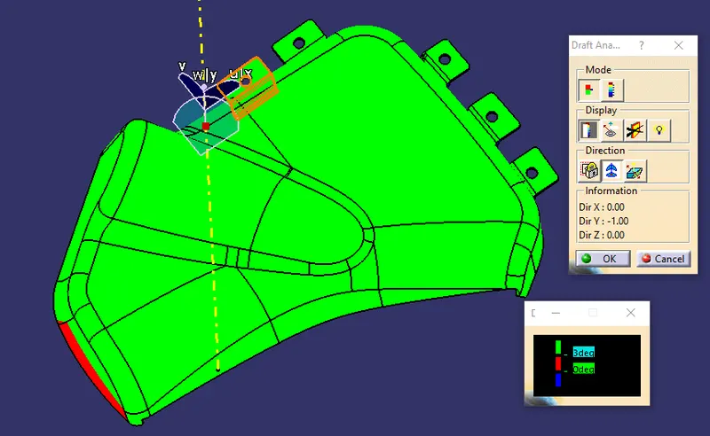
Draft Analysis on CLASS-A surface:
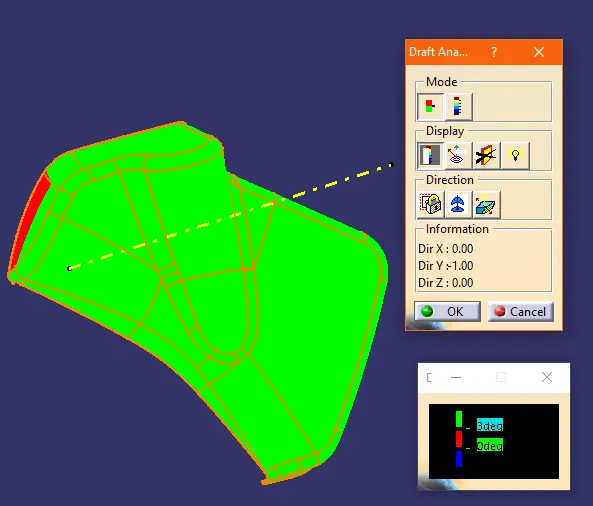
To ensure if the Tooling Axis we created is proper, we need to inspect the CLASS-A surface by performing a Draft Analysis on it.
CLASS-B surface:
To create the CLASS-B surface, the CLASS-A surface is offset by 2.5mm (since the thickness of the component is 2.5mm). From the master sections which is given to us as input, we can measure the thickness of the component. At times few surfaces of the CLASS-B surfaces cannot be offset due to the change in the fillet region. These issues can be fixed by creating the surface manually in those portions. Since there are no issues on this surface we can proceed to the next step.
CLASS-C surface:
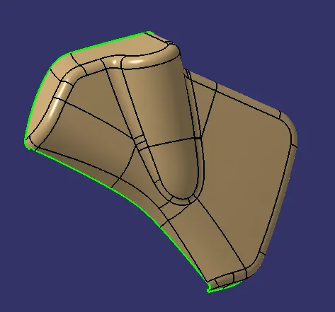
To create a CLASS C surface first extract the boundaries of the CLASS A surface.Now using the ‘sweep’ option create the C surface by sweeping the boundary of the CLASS-A surface at an angle of 3deg outwards to the tooling direction
Join all these sweep surfaces to form the final C surface.
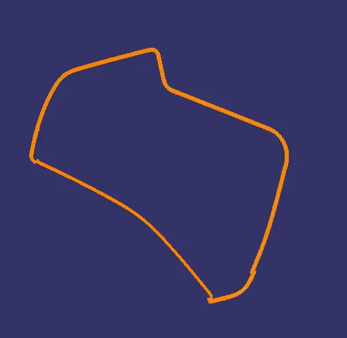
Close surface :
To form a closed surface we first need to join the CLASS A surface with the CLASS C surface and then trim this joined surface with the CLASS B surface to get the final output.Check if there are any gaps after joining the surfaces by using the boundary option. If there will be any gaps after the joining of surfaces then these gaps need to be fixed to form a closed body
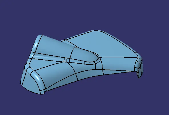
Using the “CLOSE SURFACE” option in PART WORKBENCH, a solid body from the closed surface can be formed.
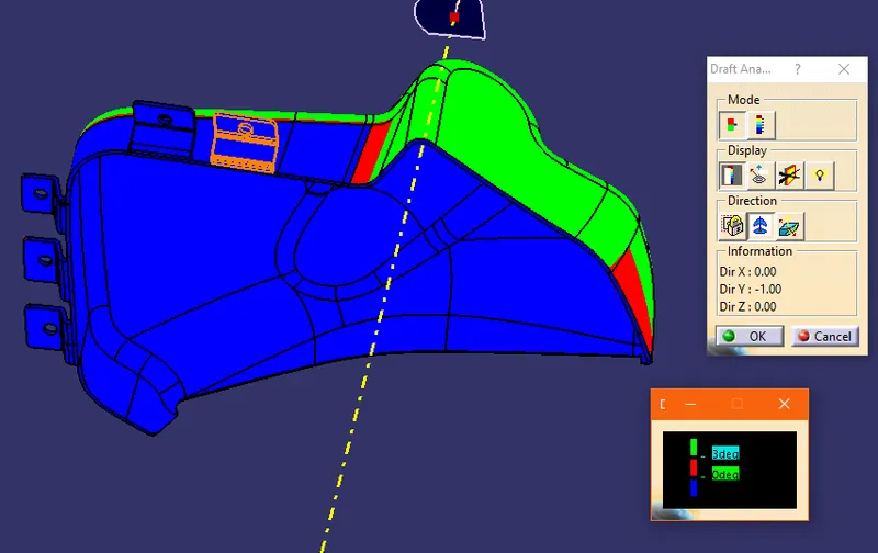
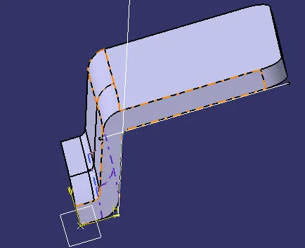
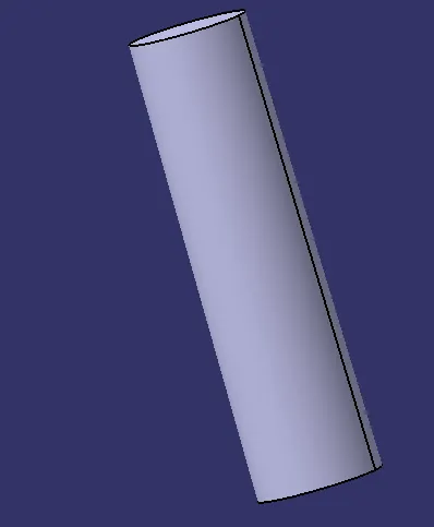
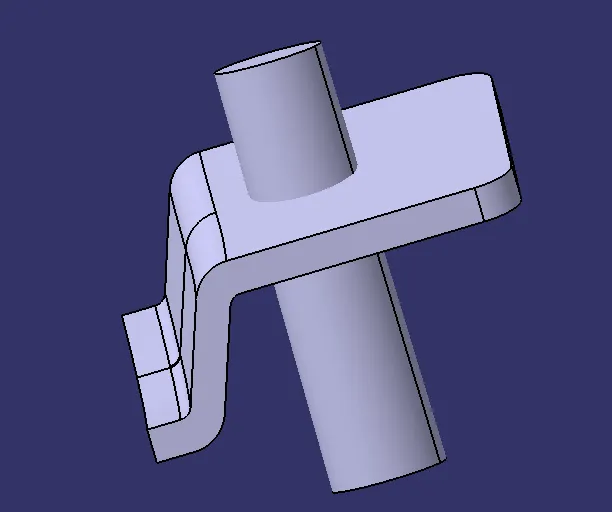
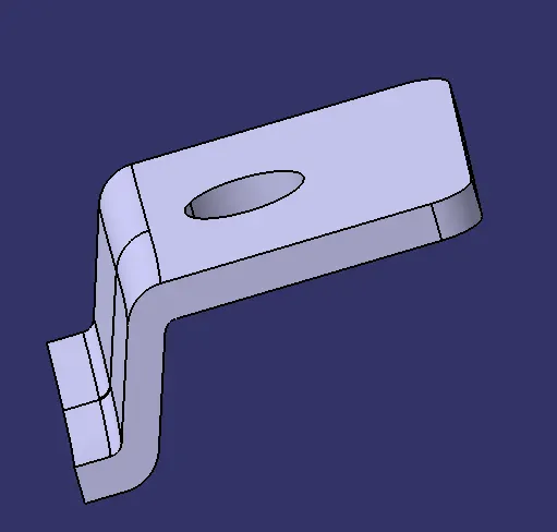
FLANGE
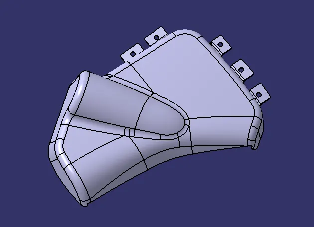
A flange is a protruded ridge, lip, or rim, either external or internal, that serves to increase strength (as the flange of an iron beam such as an I-Beam or a T-beam); for easy attachment/transfer of contact force with another object.
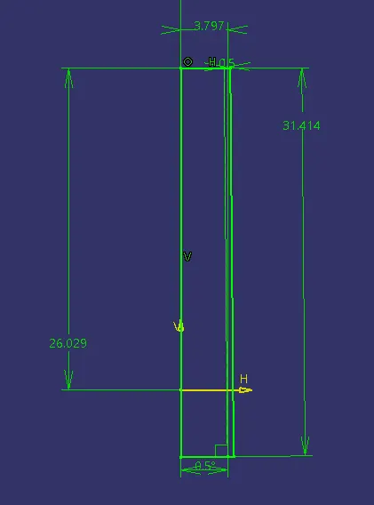
According to the design rule and master, the section provided the flange thickness should be equivalent to the plastic component for rigidity and strength.
A minimum draft of 0.5 degrees is given as per the master section.
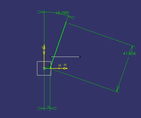
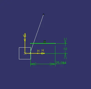
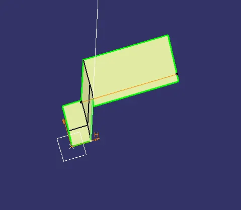
DOG HOUSE:
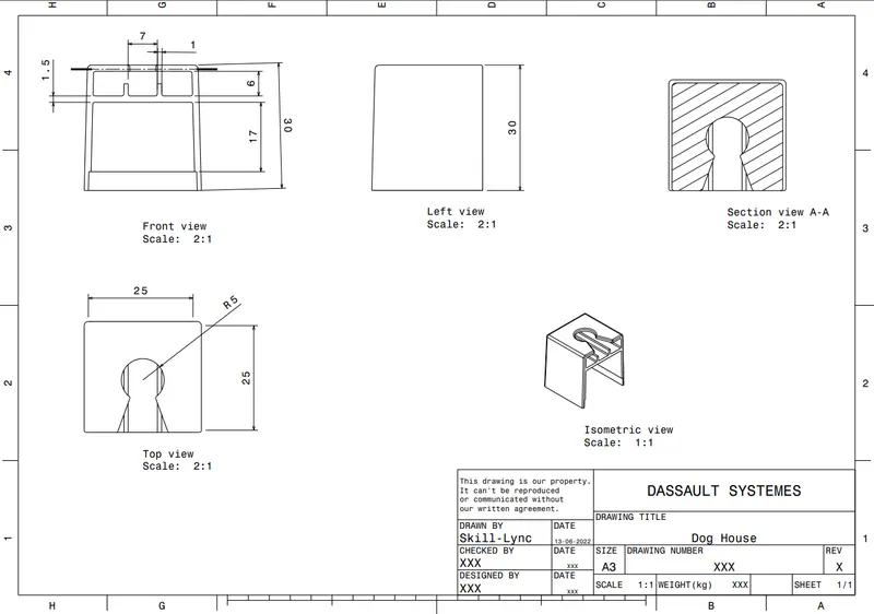
The dog house is an engineering feature used in the plastic trim design. Dog houses are used as supporting features. Sometimes other engineering features like snaps; locators, etc. are mounded on them to increase their strength.
- Draft 1.5 degree on all walls
- Intersection of part wall Thickness= 0.4* T
- Height =3<->6mm
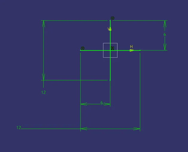
- Width of dog house =12 mm
- Fillet value 0.25mm
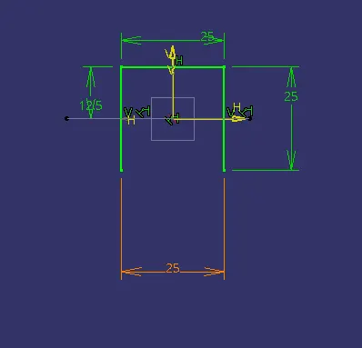
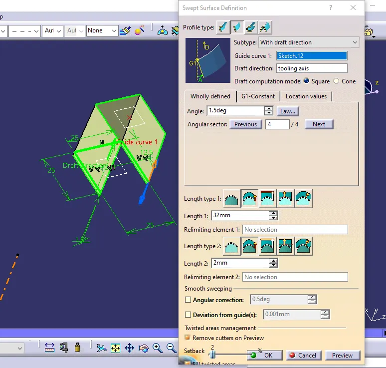
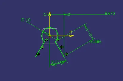
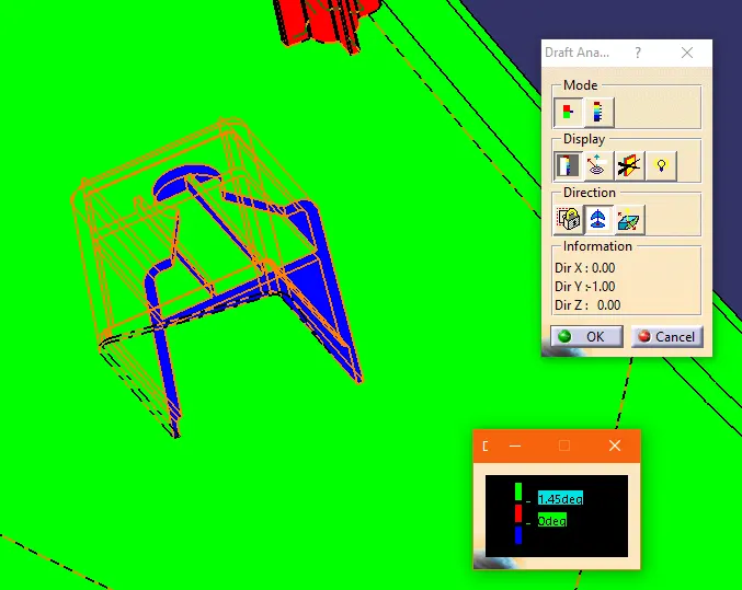
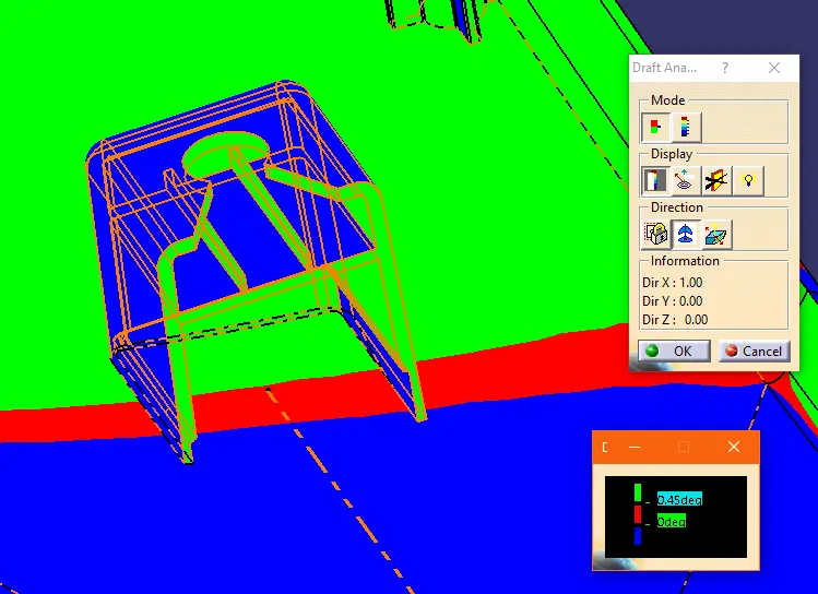
The sketch is swept in the draft direction with 1.5 degrees.
The base surface is offset and trimmed to form a cube with no front face.A thick surface is given in Part design.Fillets 1mm are given according to the height of the dog house.
To create coring 1mm width and 4mm height is selected inside the dog house created.
Offset the base to 3mm and trim it with the original sweep to create a box.
Using a thick surface gives 1 mm outward extrusion, and using the remove command cut the part from the main dog house body.
A hole for pushpin is needed so according to the sketch the surface is extracted and split with the dog house to create the hole for push pin fit.
HEAT STAKES:
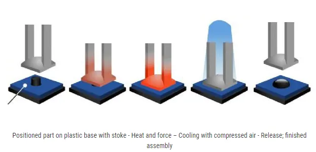
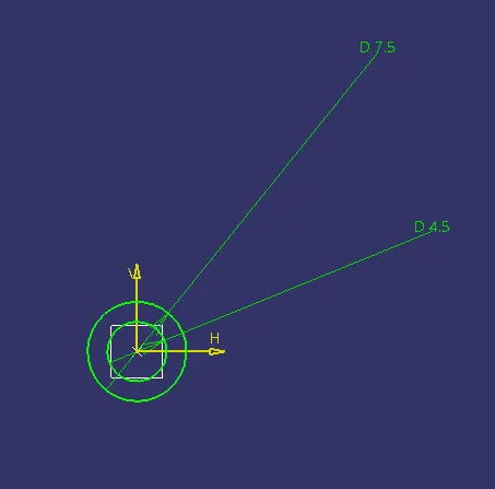
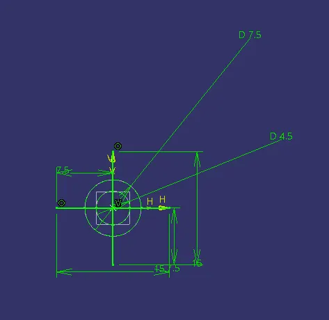
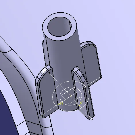
Heat Staking is a pulsed-heat process to join two or more parts out of which one at least is made of plastic. The process is to deform the plastic material using heat and force at a set process time. The bond is made by partially de-forming the plastic part to fix the other.
SKETCH:
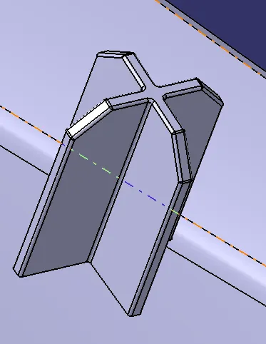
4 WAY LOCATER
3-2-1 Principle:
To locate a part to be machined and restrict its motion to accurately do the machining and constraint its motion 3-2-1 principle of location is used.
To completely specify the position in space of a three-dimensional
object (such as the cube that’s shown), we refer to six coordinates:
- Translational position along the X-axis
- Translational position along the Y-axis
- Translational position along the Z-axis
- Rotational position about the X-axis
- Rotational position about the Y-axis
- Rotational position about the Z-axis
It is a 3 step process of introducing 3-2-1 point locators in a plane for best support and constraint.
For example, let's say we use 3 points at the bottom of the cube above, which restricts the translational motion along Z(Z+ and Z-), Rotational motion along Y and X(7, 8, 9, 10) This way three degrees of motions have been restricted.
Now we use 2 points from the Y+ direction of the cube to restricts the Translational motion along with Y(Y+ and Y-), Rotational motion along with Z. This way two degrees of motion are restricted.
Finally to restrict motion along the only remaining degree of freedom that is the TranslOTENational motion along the X(X+ and X-) a single point is used along the X+ direction of the cube to restrict all the motion.
According to the above principle and using it as the base for creating points for perfectly restricting any movements of parts in the body when attached to the main door panel, I placed required flanges and heat stakes along the body.
For attaching the flanges to the body, I used the add command with translation and rotation command to fix the two parts.
FINAL PART
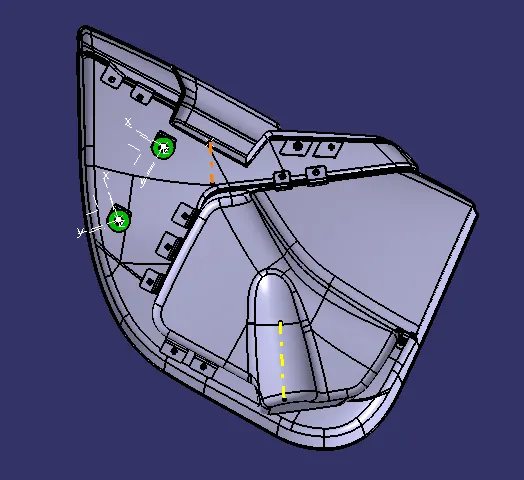
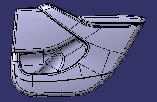
Result & Conclusion:
Door Trim Panel with engineering features using the master section and styling surface as an input has been successfully created and draft analysis has also been performed for the same."