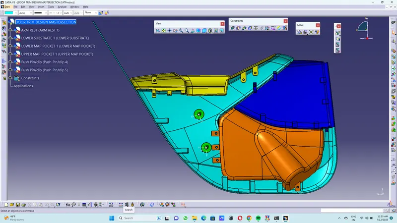
Week 12- Final project
DOOR TRIM DESIGN USING MASTERSECTION
Aim:
The Creation of CAD model considering Class A Surface,Mastersection and the attachement strategy.
Objective:
To creation of CAD model considering Class A Surface,mastersecttion and atttachment strategy.
Create the thickened part using the mastersection for reference.
Create the mounting features as per the guidelines in the industry and with mastersections.
Apply material details.
Draft Analysis and tooling axis.
Introduction:
10 stages of product life cycle of automotive industry are,
1.Concept sketch
2.Styling Class A
3.Feasibility Check
4.Concept validation
5.New product Design
6.Product Development
7.Proto Built
8.Design Validation
9.Pilot Production
10.Mass Production
In this product life cycle we going to see about the New Product Development CAD,
In this stage the major work of product design will takes place from the concept sketchto validate the product to go for the design using the design software like (Catia,NX CAD and Solidworks).In this stage the Design of all the surface were divided into subparts from the Class A Surface and wheather check the product should be working.then in the class A Surface of subparts within the help to makes the 3D model and 2D Drawings for development.then the product design is completed.
Class A Surface:
The Class A surface was given with STP file and the given Class A Surface of Door trim Designs are
1.Arm Rest
2.Lower Substrate
3.Lower Map pocket
4.Upper Map pocket
Class A Surface of Arm Rest:
The given Class A Surface has some modifications and patches are clear fron the class a surface and the tooling axis was created on the class A Surface.
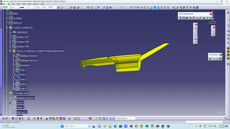
Tooling Axis:
The Tooling axis was created by the intersecting option the tooling axis was created.
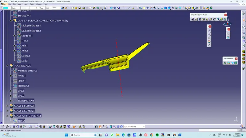
Class B Surface:
The Class B Surface was created by the offsetting of 2.5mm from the modification of class A Surface.During Offsetting the Class B Surface creates the some patches and those patches were solves and class B surface was created.
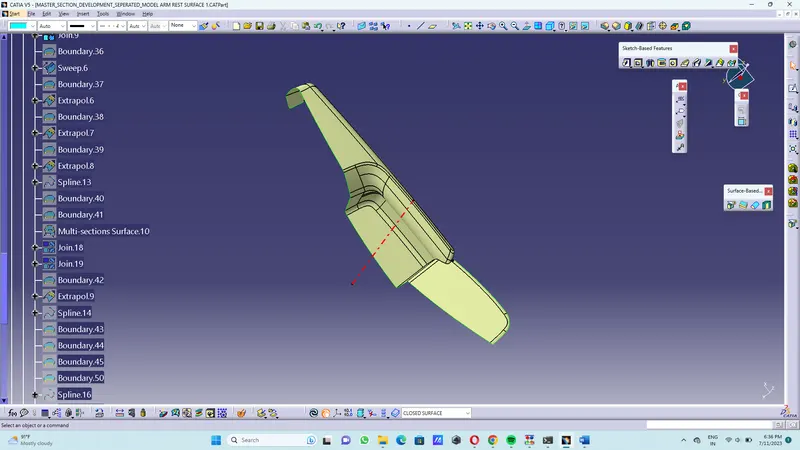
Class C Surface:
The Class C surface were created fron the class A surface and using sweep option the Class C surface were created.
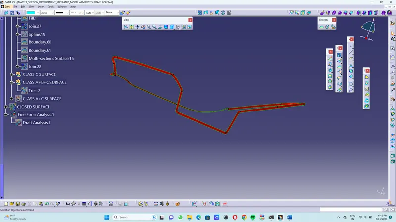
Class A+C Surface:
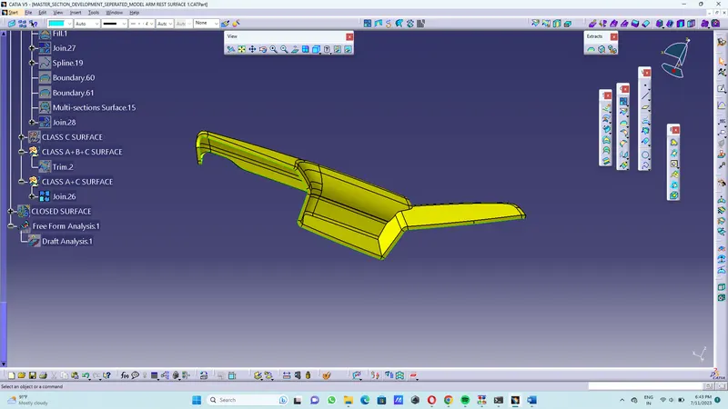
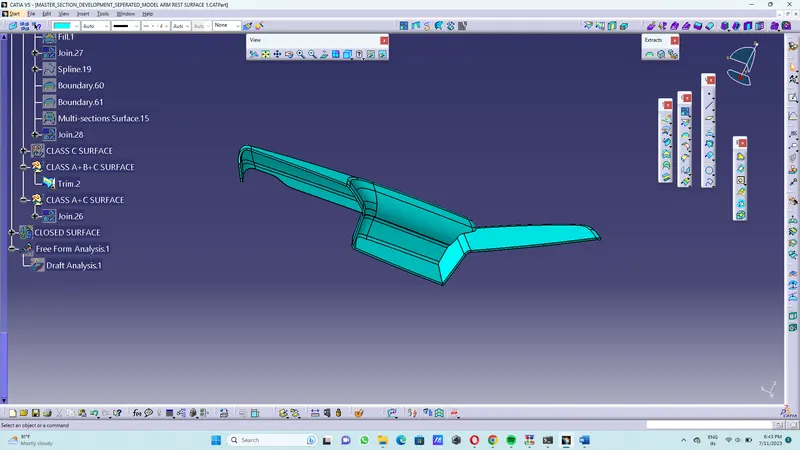
Class A+B+C Surface:
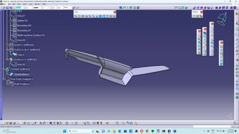
Closed Surface:
Attachment Features using the master section:
In the Closed surface of the Class A+B+C surface the Attachment were created by the given mastersection by taking extraction from the mastersection for the armrest and flange with the heatstakes and the locators were created by the mastersection.
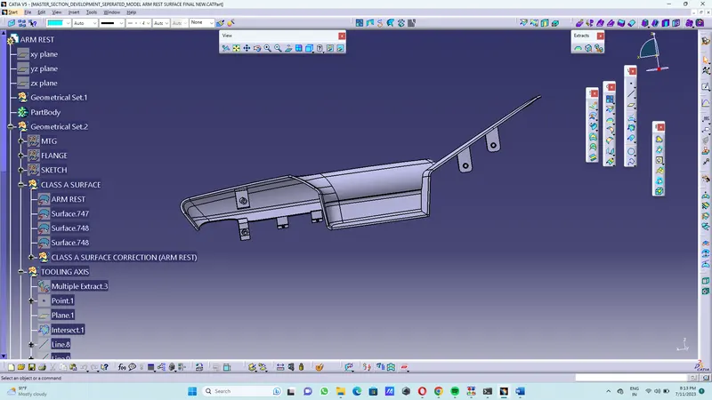
Draft analysis on Arm Rest: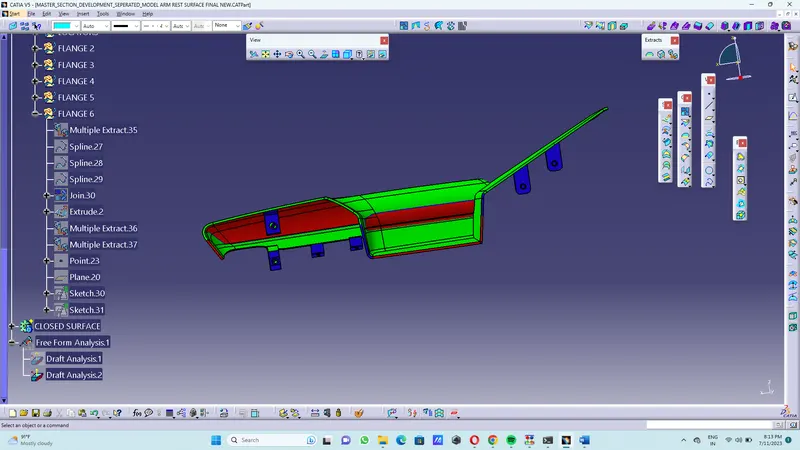
LOWER SUSTRATE
Class A Surface:
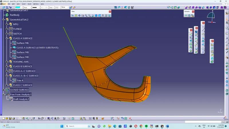
The Class A Surface was given as STP or part file if there is any modification in the class A surface were corrected.and in the class A surface tooling were created.
Tooling Axis:
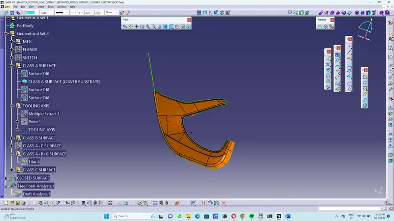
The tooling axis was created by the direction of the y component with flat surface,the tooling is created.
Class B surface:
The Class B was created from the offsetting of 2.5mm from the class A surface.during the offsetting if some patches created then patches will be corrected and class B surface were created.
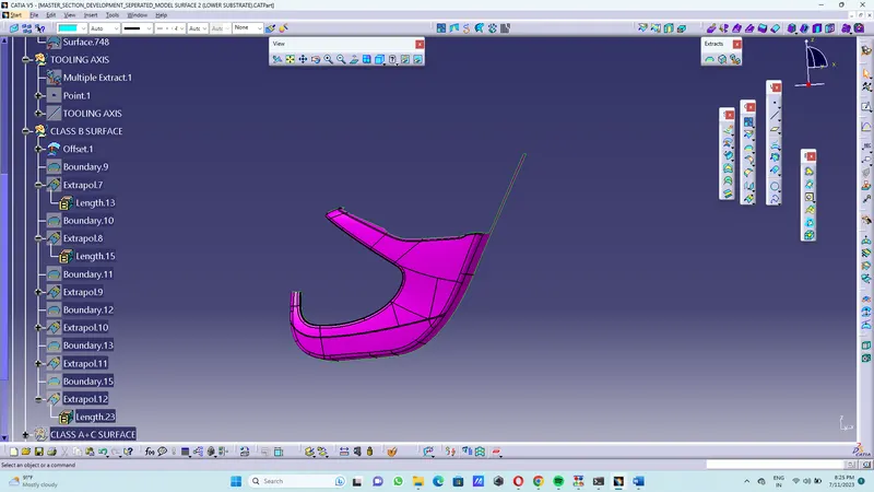
Clas C Surface:
The Class C Surface was created from the class A surface by the sweep option by the function with reference surface with 90deg direction.
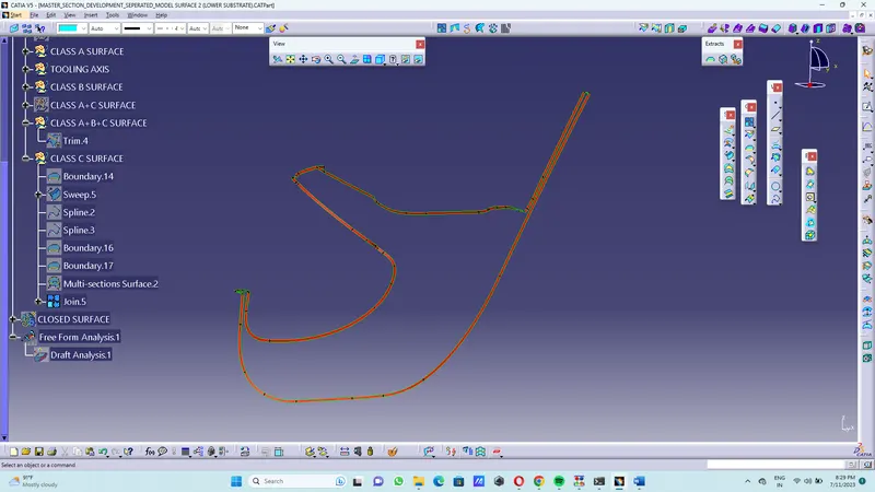
Class A+C Surface:
The Class A+C Surface were bu the joining of the two surfaces.
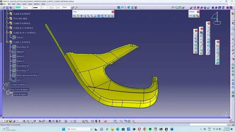
Class A+B+C Surface:
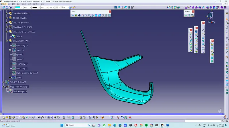
Closed Surface:
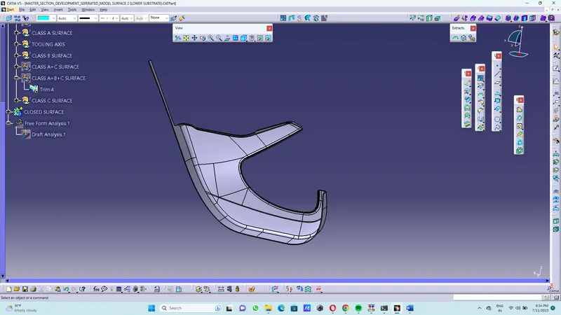
Closed Surface with Attachment:
In the Closed surface Attachments was created by the mastersections and the 2D drawing from the attechments were drawn and the design the attachments and other features were created.then the dog house were created on the Closed surface with some design rules and in the top of the dog house we want to kept the push pin.
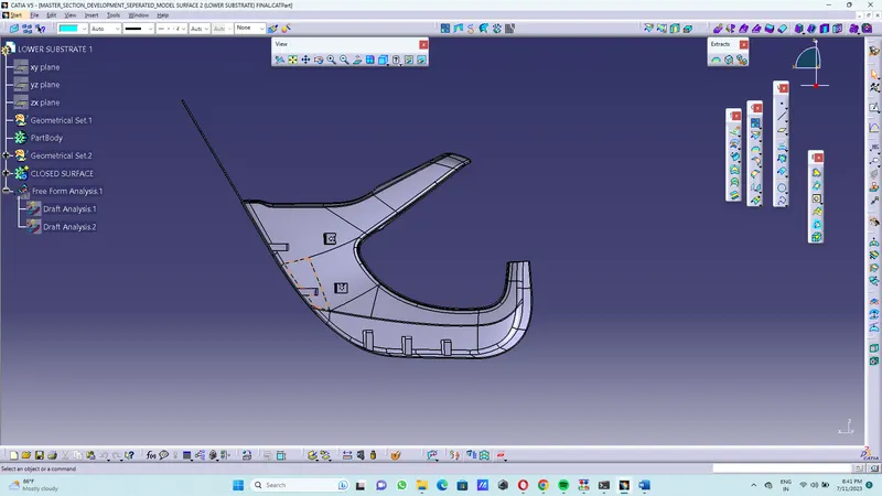
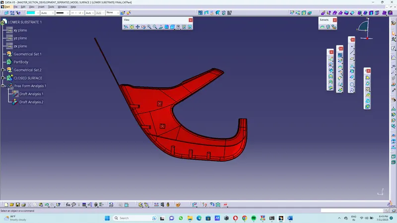
Draft analysis on Closed Surface:
UPPER MAP POCKET:
Class A Surface:
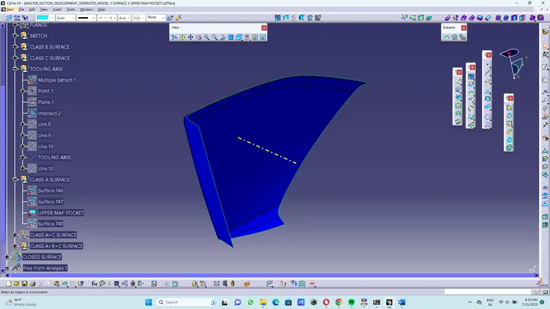
The Class A Surface was given as the Catpart or STP file and if there is any modification in the Class A surface was corrected and in the class A Surface tooling was created.
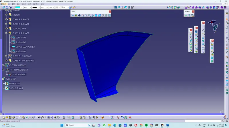
Tooling Axis:
Class B Surface:
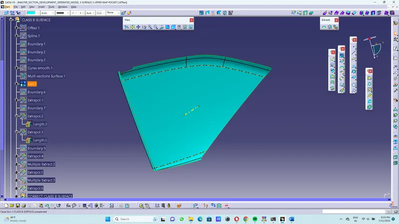
The Class B Surface was created by the offsetting of 2.5mm from the class A surface and due this offset if there is some patches were created and those patches was corrected and then Class B surface was created.
Class C Surface:
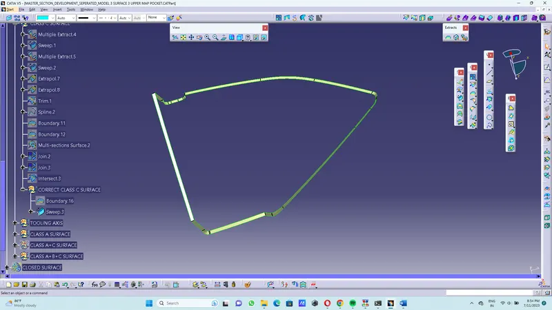
The Class C Surface was created from the class A surface an dthose class c surface created from the sweep option of 90deg direction with reference surface.
Class A+C Surface:
Class A+B+C Surface:
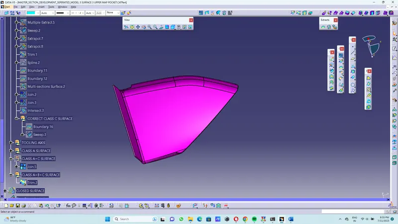
Closed Surface:
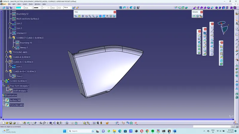
Closed Surface With Attachments
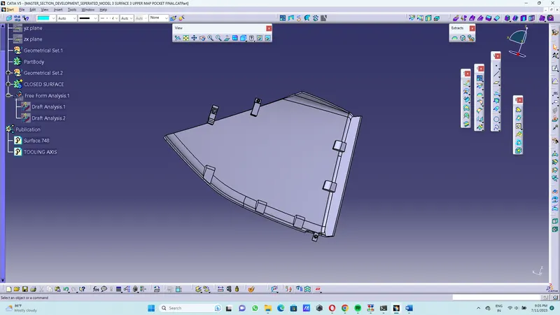
In the Closed Surface the attachments of the Flange and the ribs were created using the mastersection and in the mastersection was extracted and from the extraction Design was completed and the flange was created on the mastersection and other features also created on the closed surface.
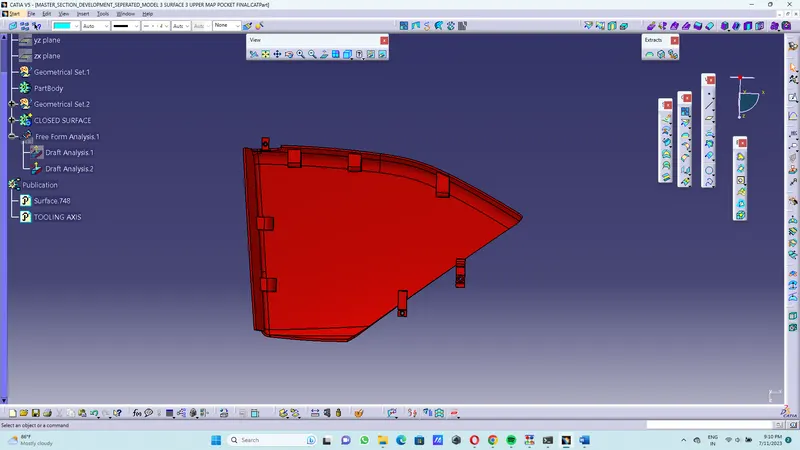
Draft Analysis on Final Surface:
LOWER MAP POCKET:
Class A Surface:
The Class A Surface was given as the STP or Catpart file,If there is any modification in the class A surface that modification are corrected and Class A surface was created.then in the class A Surface the tooling axis was created.
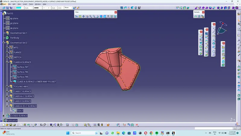
Tooling Axis:
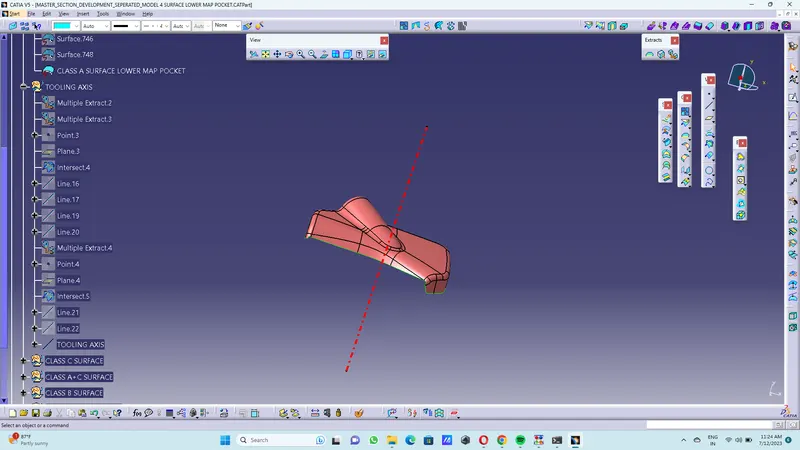
Class B Surface:
The Class B Surface was created by the Offseting The Thickness 2.5mm from the Class A surface.During this offsetting the Class B Surface creates some patches anf those patches were corrected and further proceed for the operation.
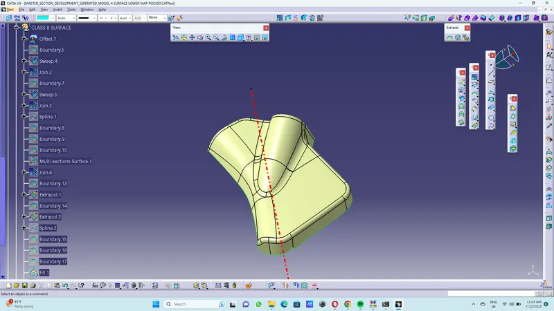
Class C Surface:
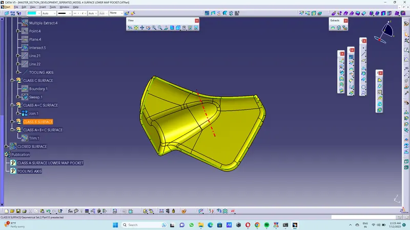
The Class C Surface was created from the CLass A surface by the Sweep operation of 90deg Direccction with refeence surface option and class C surface was created using the boundary creating on the Class A surface and also using the sweep option.
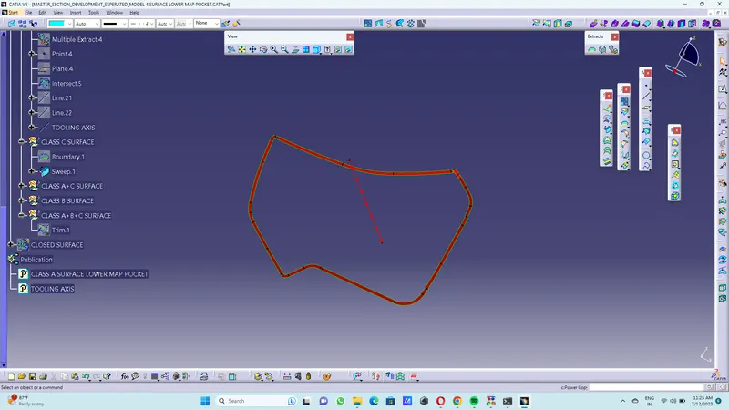
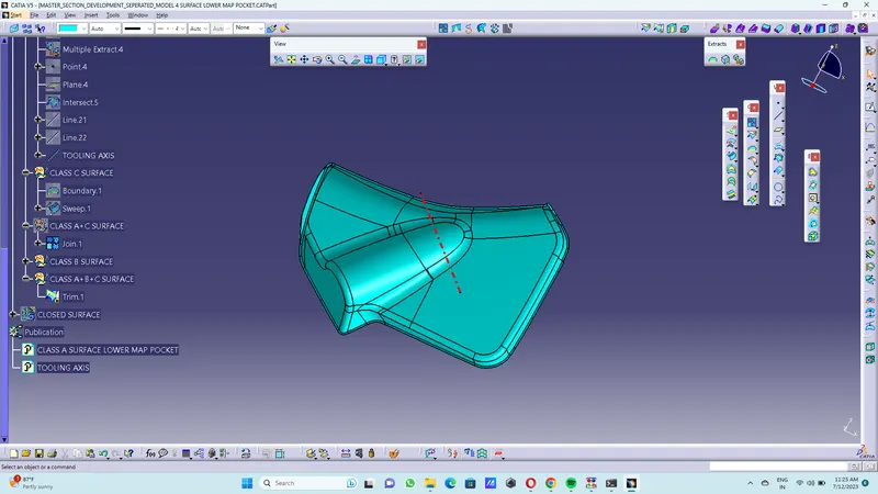
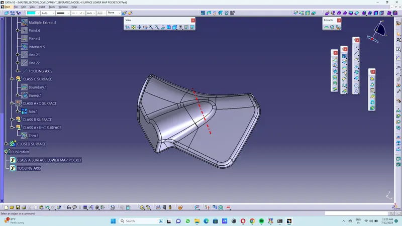
Class A+C Surface:
Closed Surface:
Attachment and Features on Closed Surface:
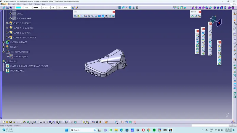
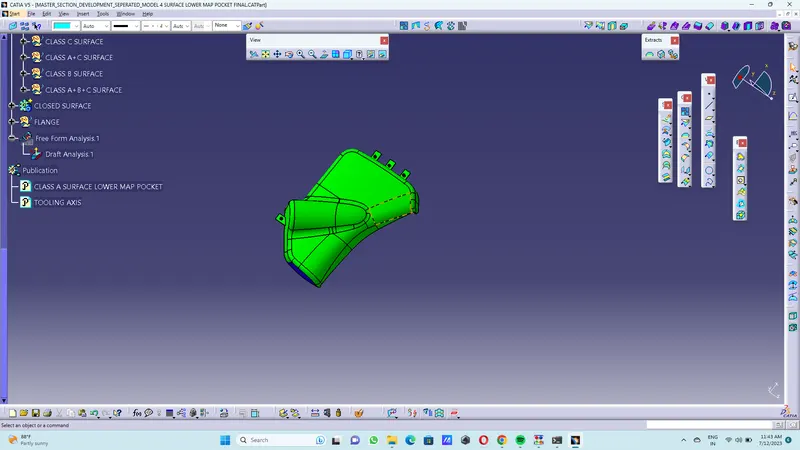
In the closed surface the mastersection is taken as the reference and attachment is design over the mastersection,from the master section the flange and other supports of the surface were designed and mastersection was used by the option of extract and in the mastersection thickness is taken and flange and the heatstakes were designed.
Draft analysis on the Final Surface:
ASSEMBLY DESIGN OF FOUR SURFACE EXPLAINED ABOVE:
The Arm rest,Lower substrate,Upper map pocket,lower map pocket are attached in the assembly or product design and ther attatched with the some engineering features,flanfe and the heatstakes.Then Dog house also created pn the surface lower substrate na din the dog house during the product the pushpin is attached by the using of coincidence option the push pin is attached to the top of the dog house.