Week 12- Final project
AIM : - Design & Development of Door trim panel Using Reference of master section and Class A surface and to strategize and attach all the components together
Objectives :-
- To create individual tooling axis for all the parts and perform draft analysis on the class A surface so that designed components has better manufacturing feasibility
- To create the class B and class C surfaces from the given refrence of class A & master section
- to create solid geometry
- To decide an attachment strategy for the part and create engineering features from the reference given from master section
- To perform draft analysis on the solid part model with all engineering features
- To assemble all the components togehter to obtain Door trim panel
-
REFERENCE DATA :-
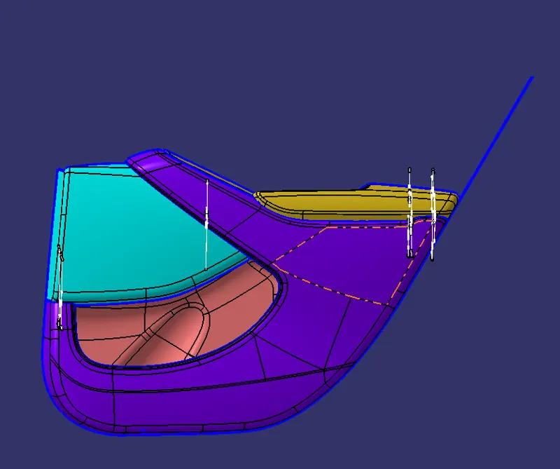
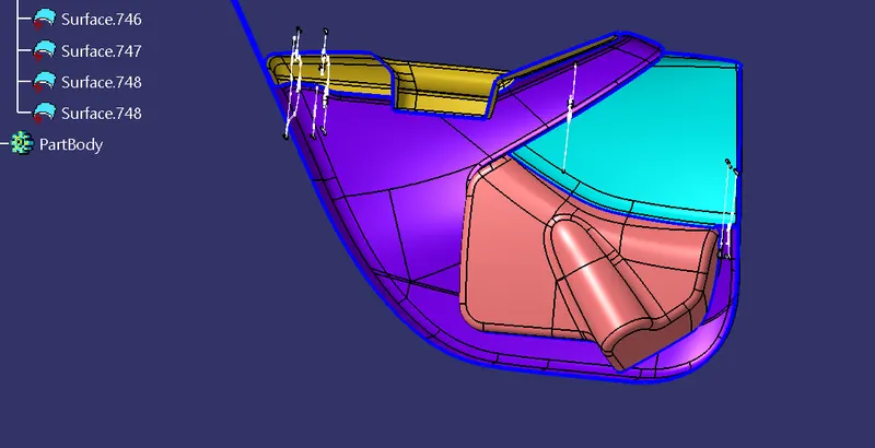
1. CLASS A SURFACE
In Automotive Industry class A surface is created by Styling Team as concept design by taking this as refrence the class b and engineering frature is designed, class A sis an essiential for designing complex surfaces
2. MASTER SECTION:
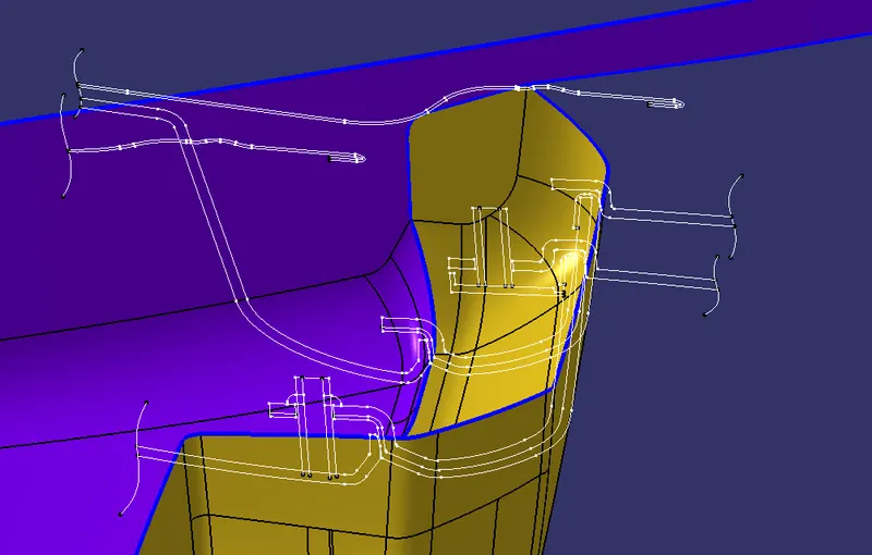
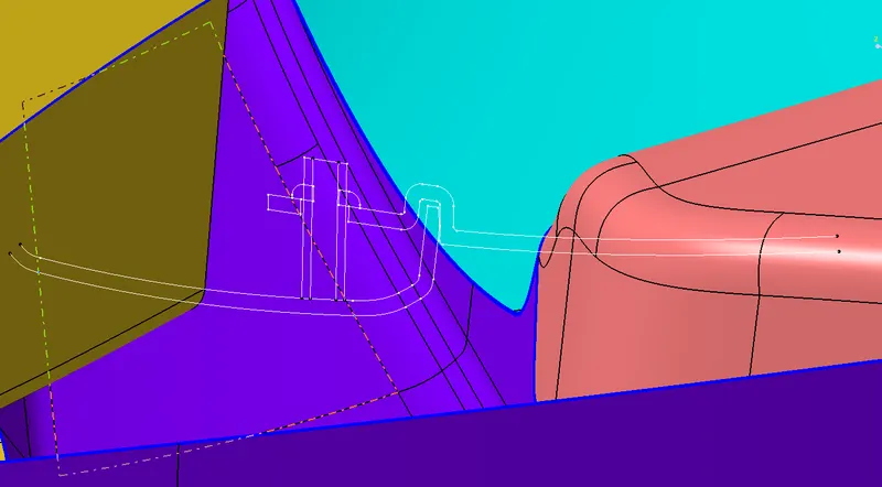
In Automotive setcor if we have any changes or development then the we mke use of master section by the help of master section sketch we get clear Idea of design and engineering feature
Steps Follwed for Completion of Project :-
The door trim panel is created by follwing steps -
- Eximanation of the Class A surface & master section checking if any modification or improvement needed
- Segrating all the Class A surface to diffrent part body
- To work individually on each part.
- creating tooling axis and checking for manufacturing feasibility
- Draft analysis on class A surafce.
- creation of Class B and Class C surface
- Creating Closed Body Using {(Class A+C)+(class B).
- creation of engineering Features
- Draft analysis of all the parts
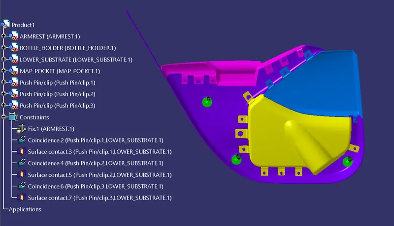
- Assembly of Push Clip
ARM REST
Class A surface
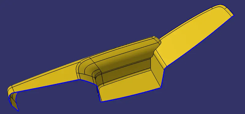
Inspection of CLASS A SURFACE
Open Boundaries found in Class A surface of Arm rest
1. Need to informing the Styling team
2. Class A improvement/ modification need to be done
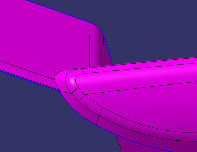
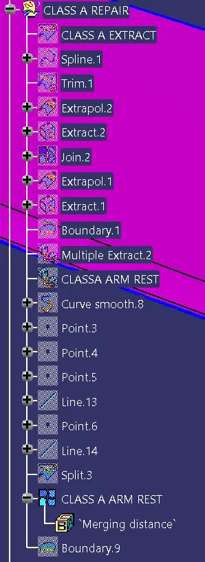
operations used for class A improvement or modifcation
Tooling Axis Creation :-
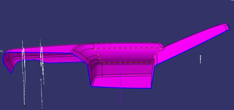
Tooling axis is created for mold ejection purpose
Here i have created tooling axis by using besecting method :
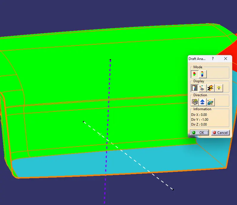
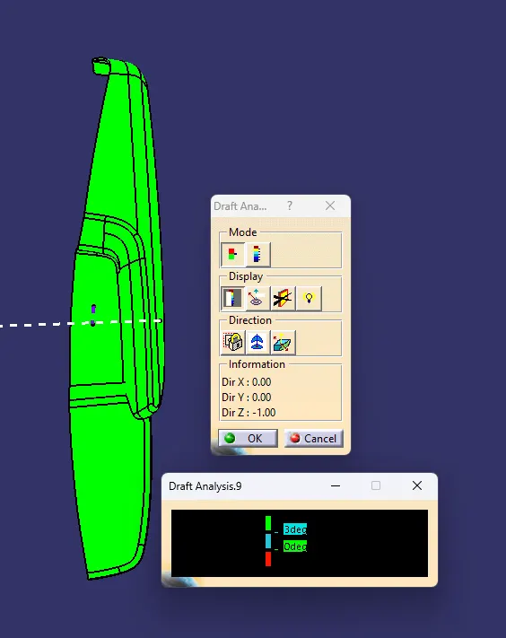
Draft analysis on class A
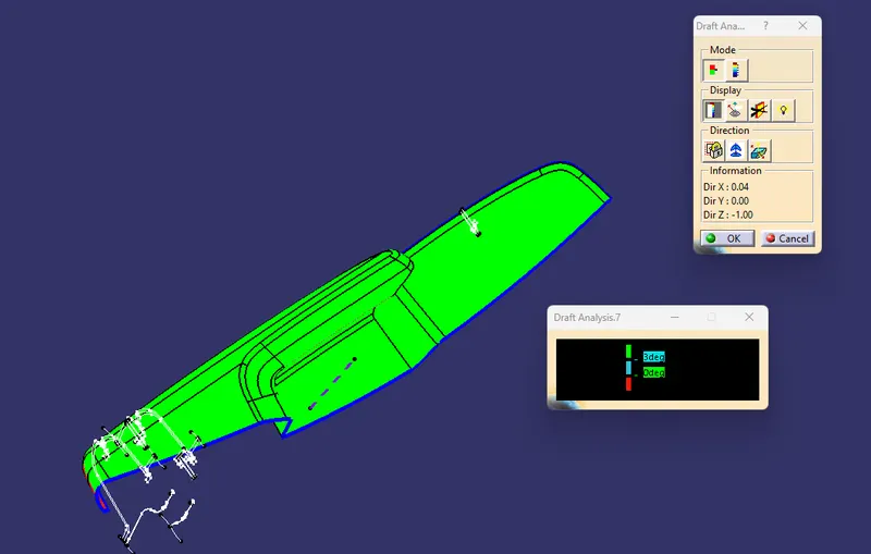
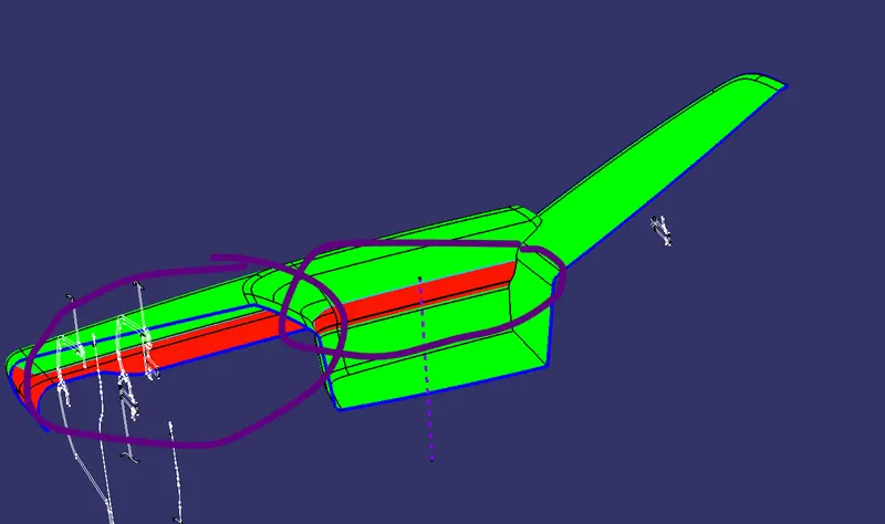
these surface are not cleared so we need 2 tooling axis
CLASS B SURFACE creation :-
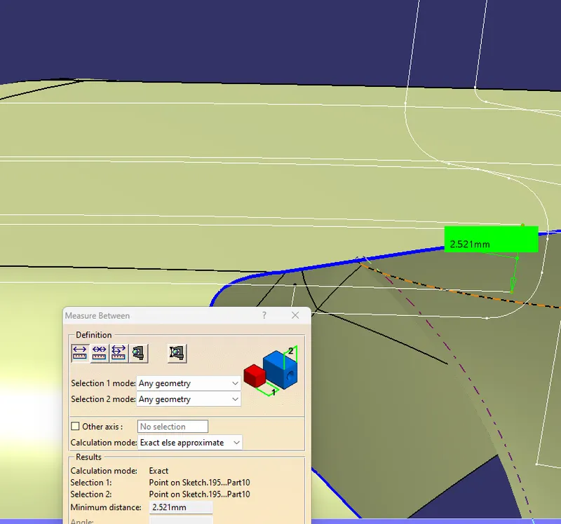
by offseting the class A surface by measuring the thickness provided in master section and the direction is also provided in master section
offset to 2.5 mm as per master section
then rework the patches occured on class b surface
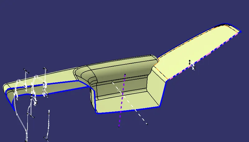
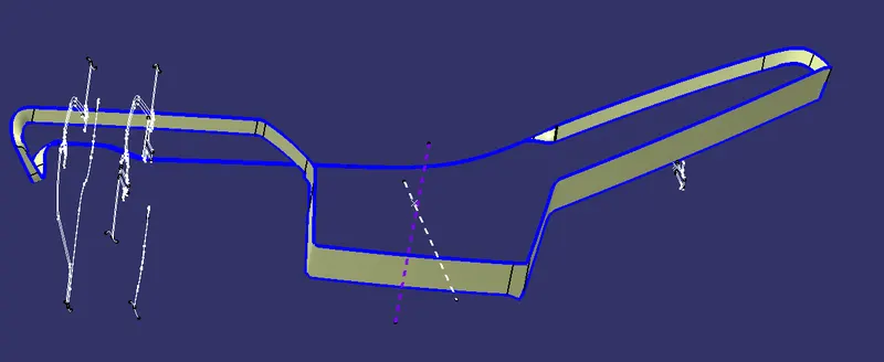
class C surface creation :-
class C surface is created using sweep feature along b oungadaries of class A
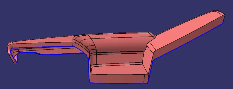
CLASS (A+C):-
join class A surface with Class C
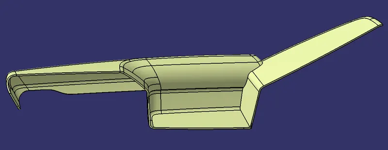
FINAL ARM REST TRIM :-
finnaly trim the Class (A+C) with Class B to get the closed body
CLOSED BODY
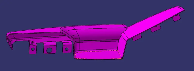
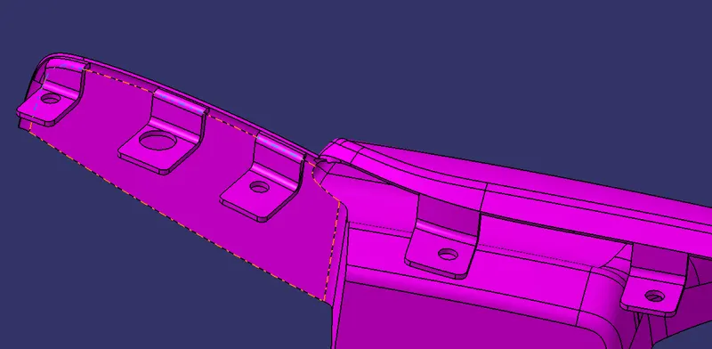
Flange Creation :-
with the help of master section create the flange
extract class c surface
extract the flange sktch and the sweep on the boundary of th class c surface
use lower substrate heat stakes location
then use split feature to cut and get desired width of the flange
the holes are done using split command
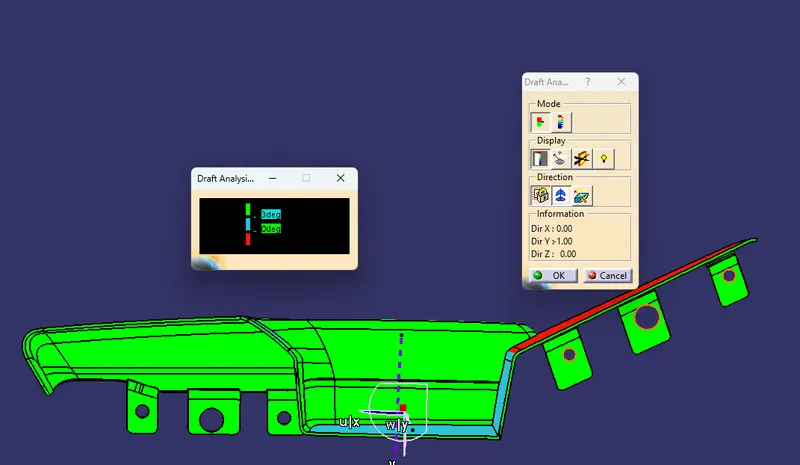
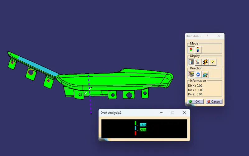
Draft analysis on solid body:-.
MAP POCKET
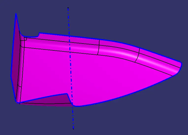
Class A surface
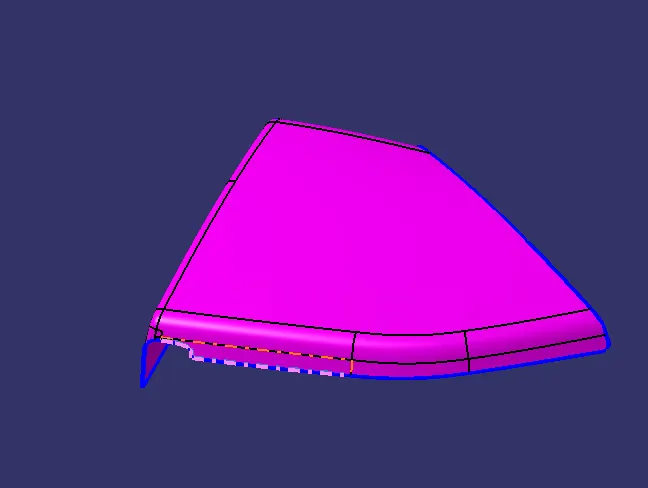
TOOLING AXIS CREATION :-
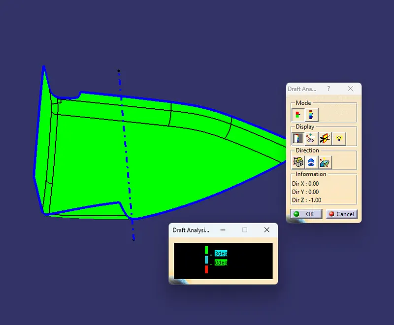
Draft ANALYSIS ON CLASS A:-
CLASS B SURFACE creation :-
by offseting the class A surface by measuring the thickness provided in master section and the direction is also provided in master section
offset to 2.5 mm as per master section
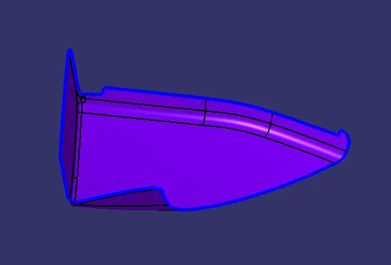
CLASS C SURFACE CREATION:
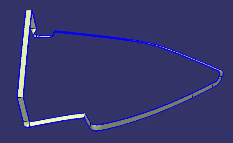
CLASS A +CLASS C :-
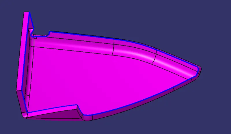
Final TRIM:-
Trim the class (A+C) with class B to get closed body
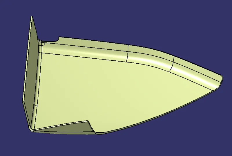
CLOSED BODY:-
use closed body command to solidify the surface
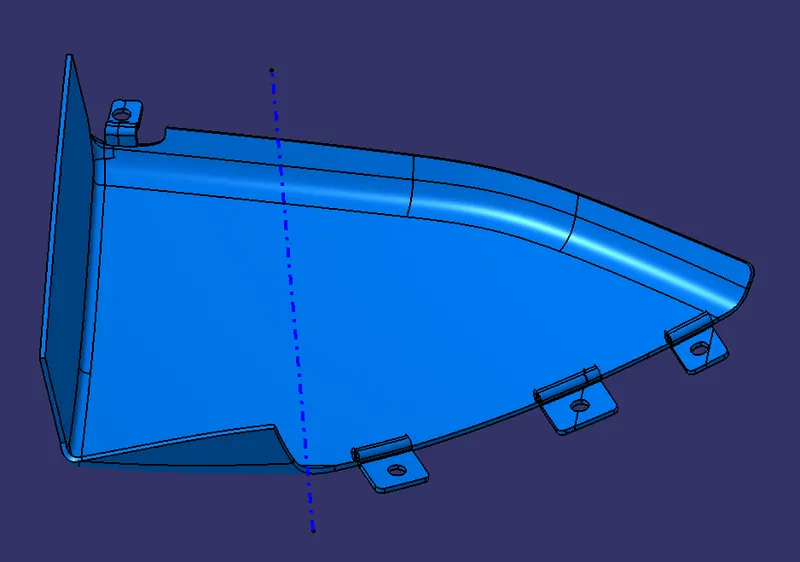
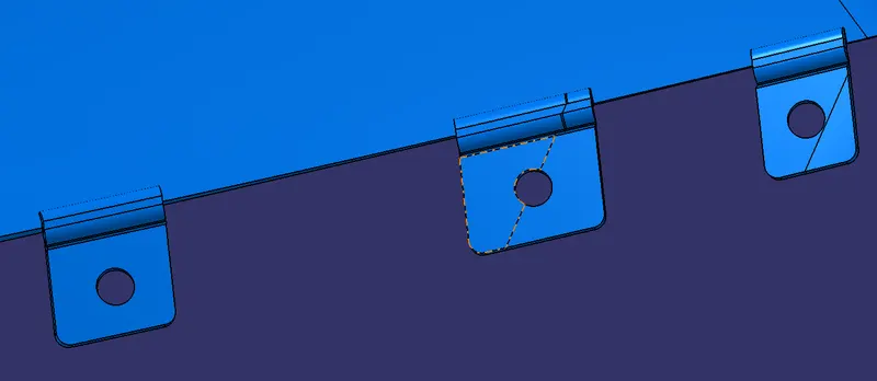
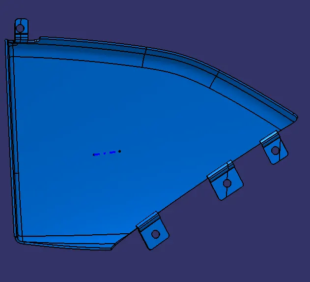
Flange Creation :-
with the help of master section create the flange
extract class c surface
extract the flange sktch and the sweep on the boundary of th class c surface
use lower substrate heat stakes location
then use split feature to cut and get desired width of the flange
the holes are done using split command
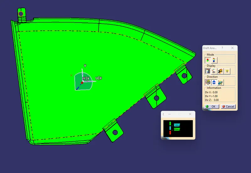
DRAFT ANALYIS OF THE FINAL MAP POCKET
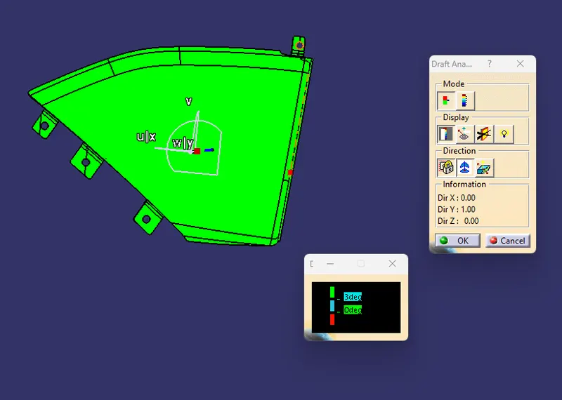
LOWER SUBSTRATE
CLASS A SURFACE :-
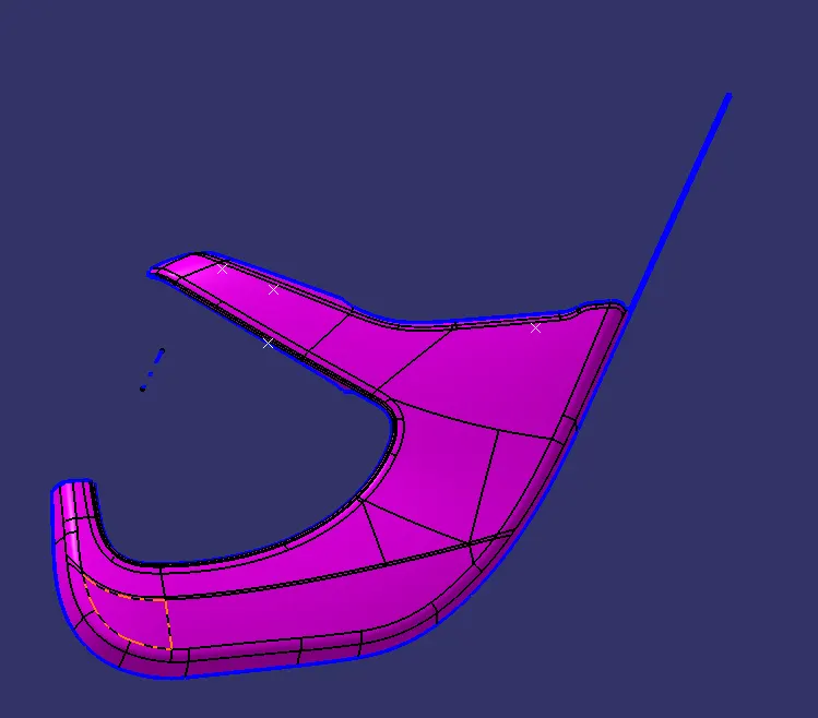
No improvement needed on class A surface
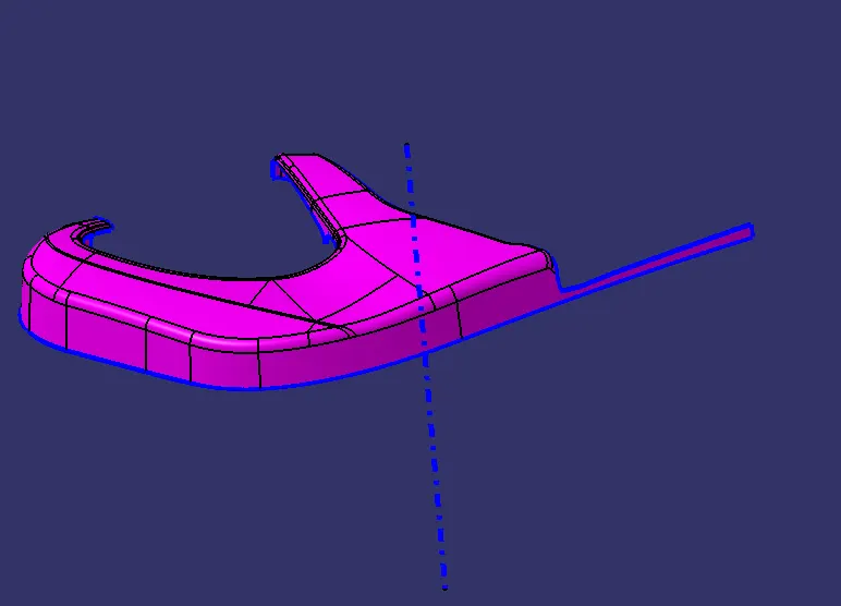
TOOLING AXIS CREATION:-
CLASS B SURFACE CREATION :-
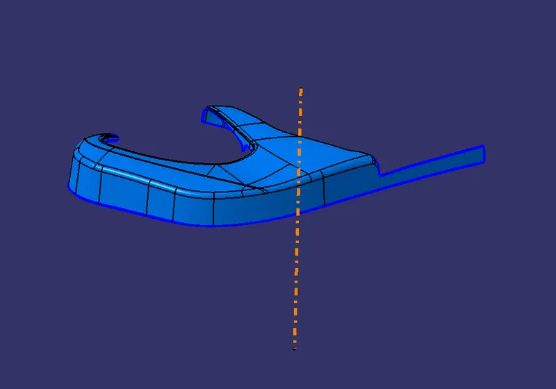
CLASS C SURFACE CREATION :-
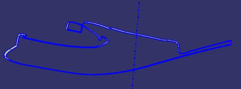
CLASS (A+C) SURFACE:-
JOIN CLASS A+ CLASS C
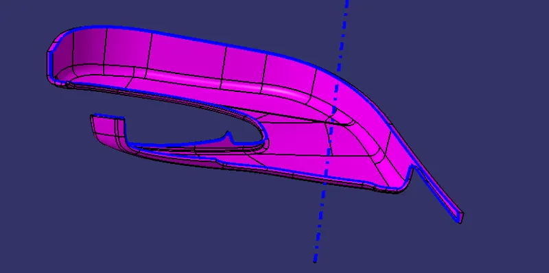
FINAL TRIM:-
TRIM THE CLASS (A+C ) WITH CLASS B
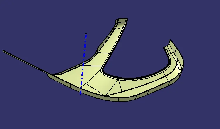
CLOSED BODY:-
use closed body command in part design to solidify the surface
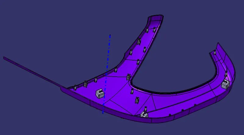
ENGINEERING FEATURES:-
HEAT STAKES:-
Heat stakes are designed accordings to design guide lines
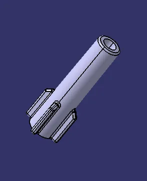
- Heat stakes are used in thermoplastics to assemble two parts together by locally heating and cooling the plastic material and allowing it to reform itself and act as a joint for the two materials.
- We have placed 15 heat stakes in the model based on the reference points created by estimation.
- One of the important factor to be considered while designing the heat skates is the height of the heat skates. It should always be less than the height of the locators.
the points are created using parallel curve and repetative points for loaction of heat stakes
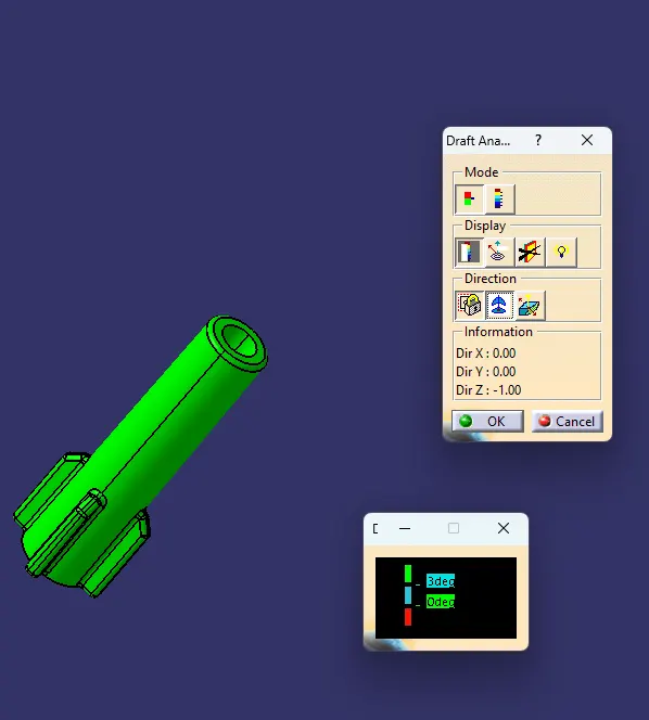
Draft analysis on heat stakes:
4 WAY LOCATORS
The main purpose of the 4 Way locators are to arrest the drgree of freedom
while assembly of mating part the locator shoul go first then the heat stakes go in
the points are created using parallel curve and repetative points for loaction of locators
DOG HOUSE :-
design:
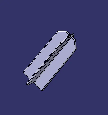
the main purpose of dog house is to avoid sink marks we can also mount engineering feature up on the dog house
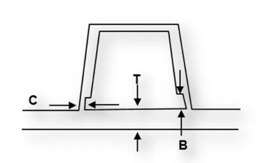
- Doghouse wall thickness at the intersection of the part wall (C) should be 40% or less than the main wall stock (T).
- The height of ( B ) should be between 3.0 – 6.0 mm
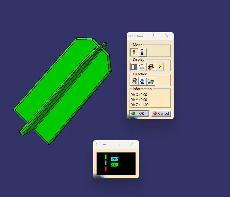
- Outer surface of dog house must have a draft angle of 3 degrees
- Inner surface of dog house must have a draft angle of 0.5 degrees
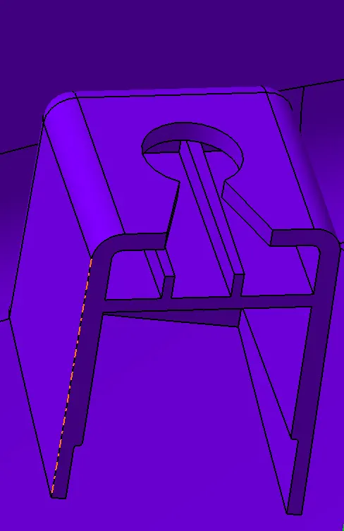
DRAFTY ANALYSIS on dog house
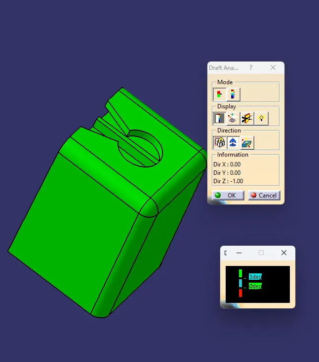
SIDE CORE AXIS draft analyis
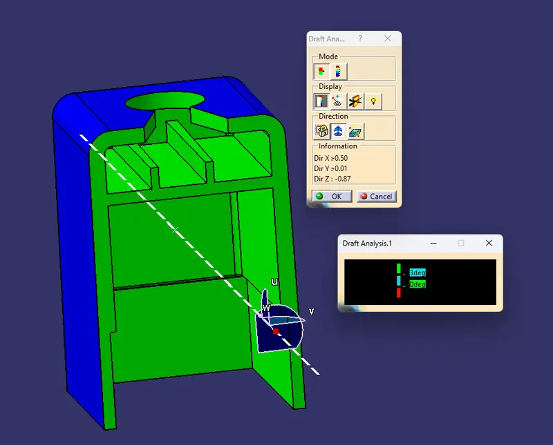
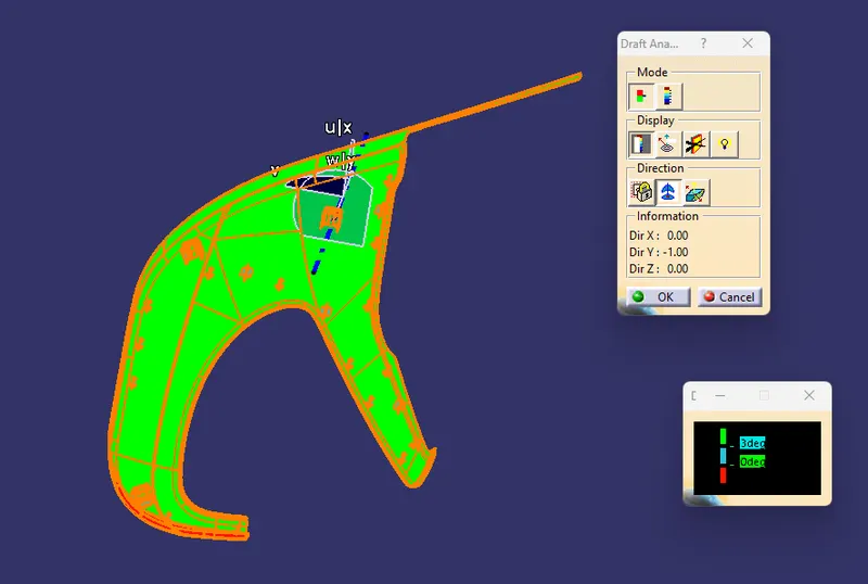
FINAL DRAFT ANALYSIS
BOTTLE HOLDER
vrs
CLASS A SURFACE
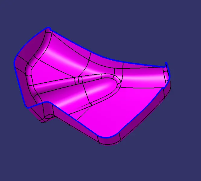
no improvement on class A
TOOLING AXIS:-

DRAFT ANALSIS
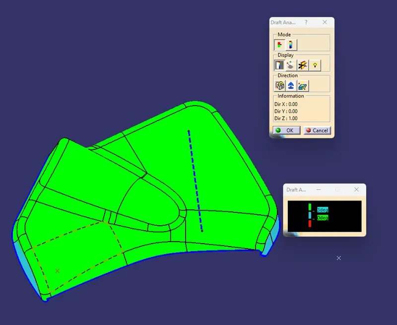
some patches are have 0 degree draft so inform styling team to repair it
CLASS B SURFACE CREATION :-
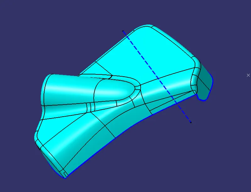
CLASS C SURFACE
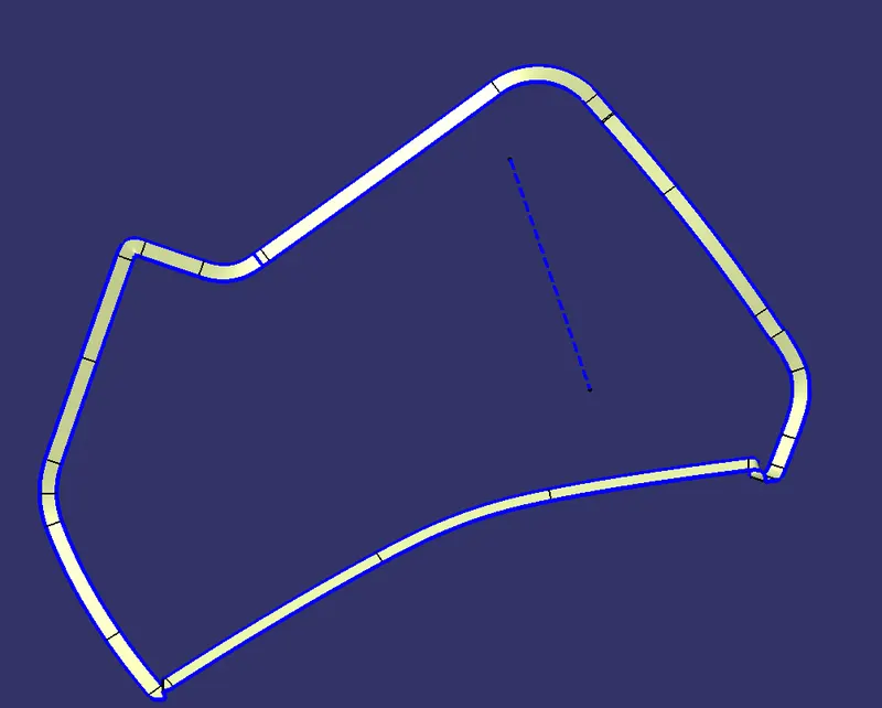
CLASS (A+C)
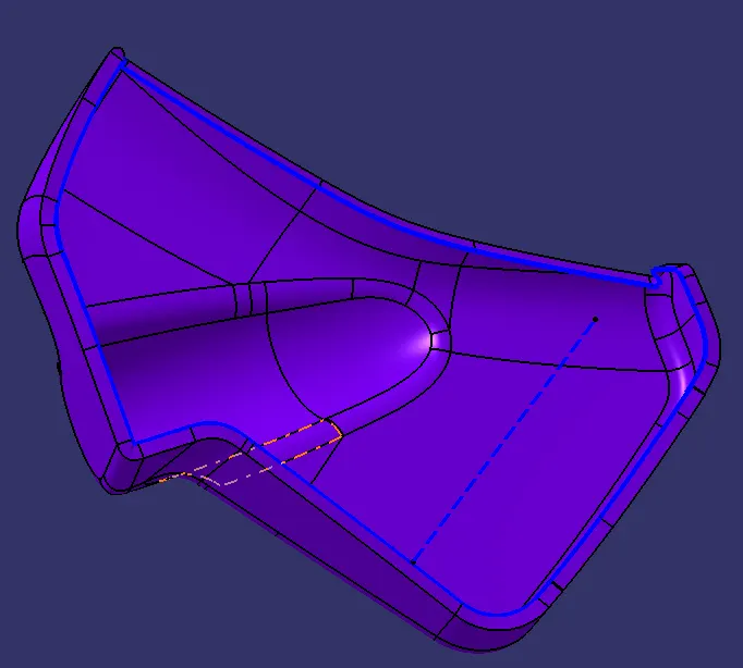
FINAL TRIM
TRIM CLASS (A+C) WITH CLASS B
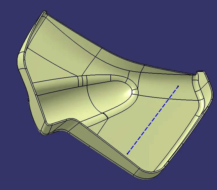
CLOSED BODY
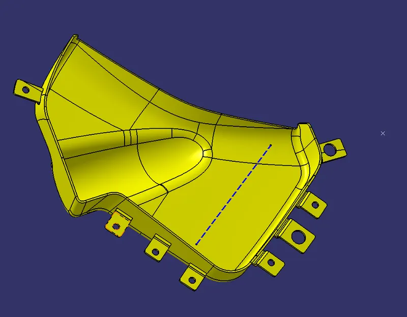
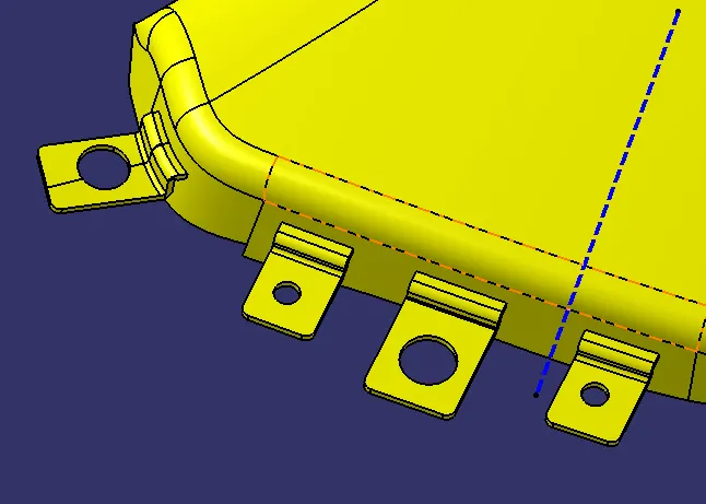
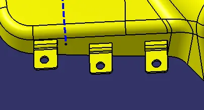
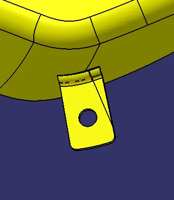
FLANGE CREATION :-
extract class c surface
sketch the flange and the sweep on the boundary of th class c surface
use lower substrate heat stakes location
then use split feature to cut and get desired width of the flange
the holes are done using split command
 B
B
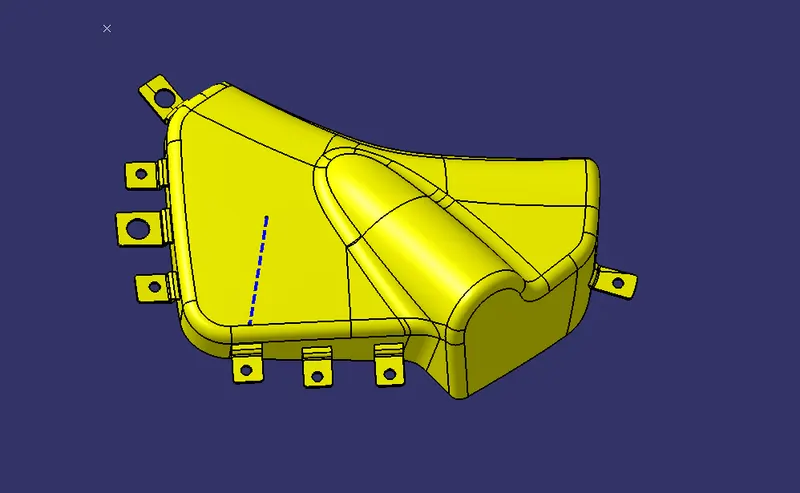
FINAL OUTPUT
D
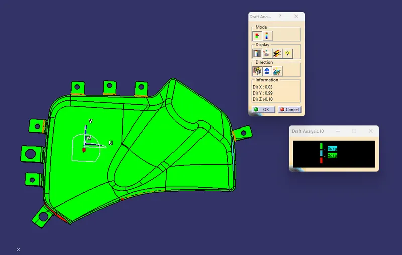
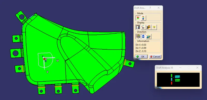
DRAFT ANALYSIS
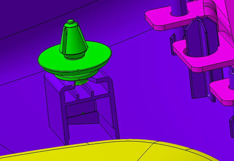
PUSH CLIP ASSEMBLY
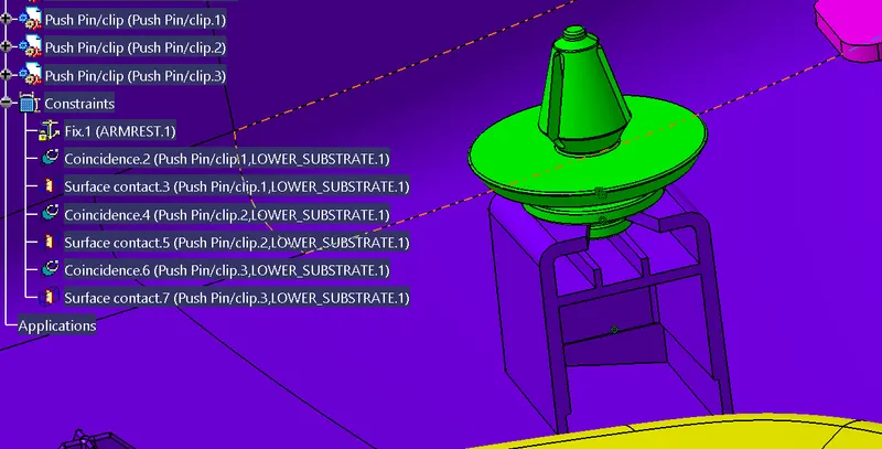
CONSTRAINS USED
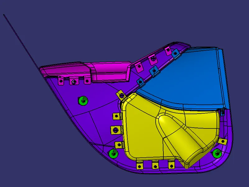
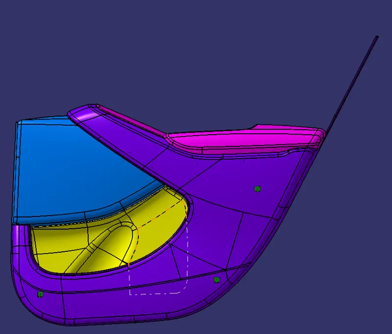
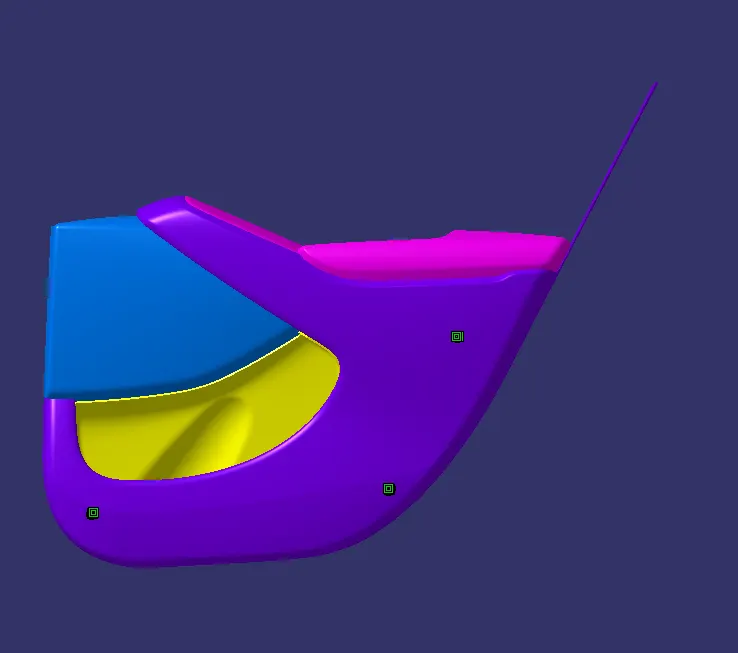
FINAL DOOR TRIM
* NOTE:
refer this cat part for all the GEOMETRICAL SET and PART BODY

THANK YOU