Week 12- Final project
FINAL PROJECT (DOOR Trim Panel)
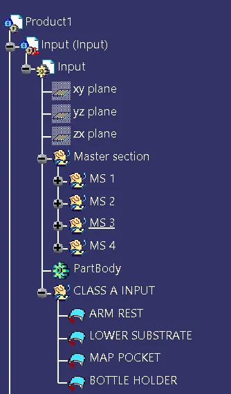
Input
Class A surface input we got along with the master section.
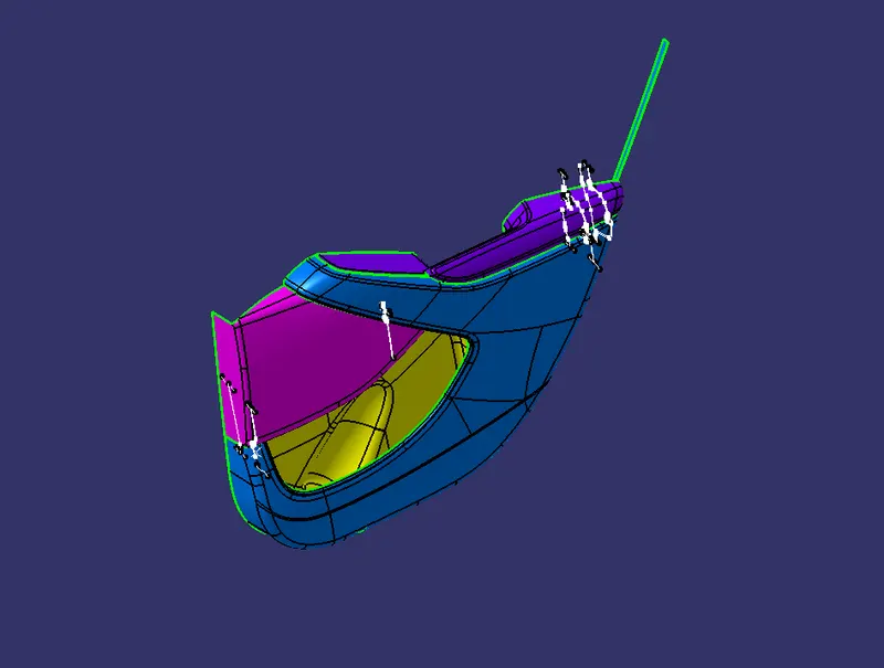
Arm Rest Class A surface
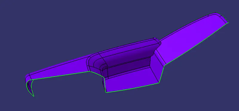
with master section
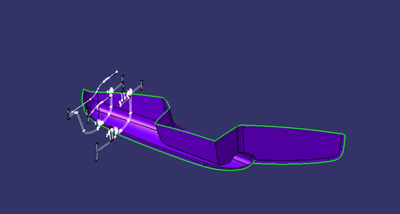
problem with this master section
class A surface we got for Armrest is not proper. the top layer is for cushioning. the armrest has a 2mm thick Cushion. the class A we got is for Cushioning. the actual part has a 2.5mm thickness. so the actual offset for class be is (2mm+2.5mm)= 4.5mm
but we considered 2.5mm offset from the given offset.
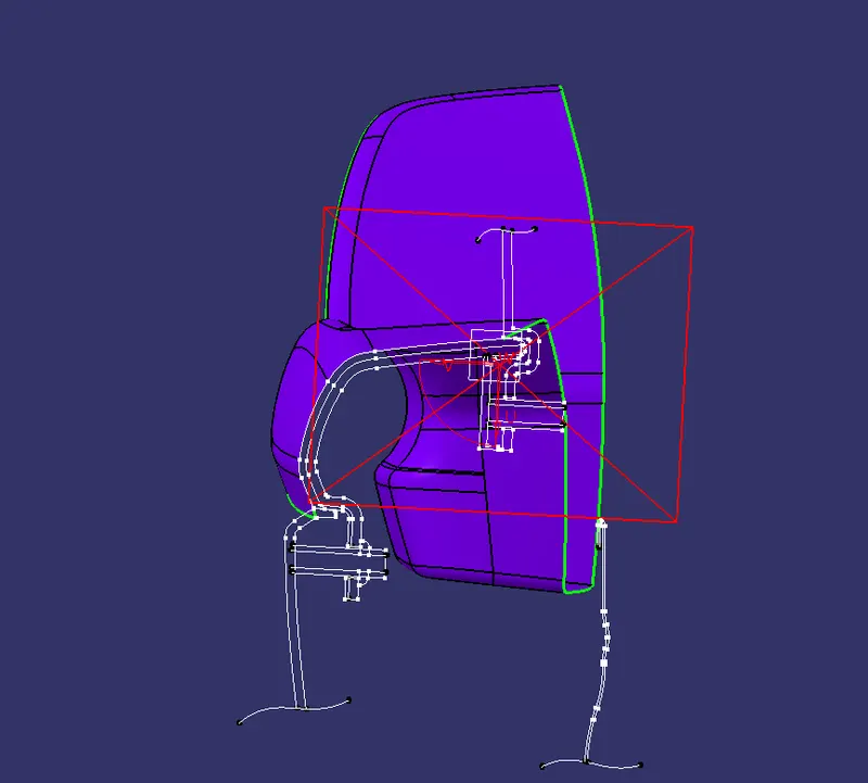
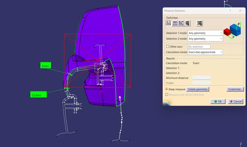
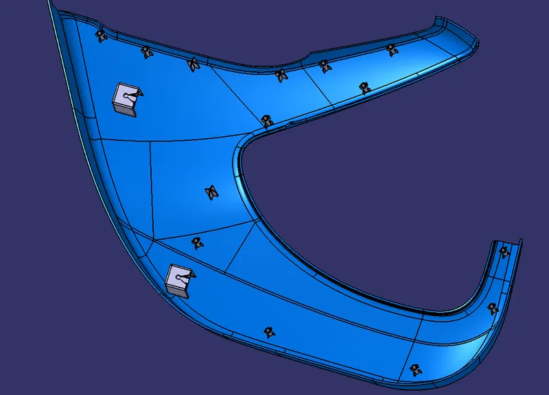
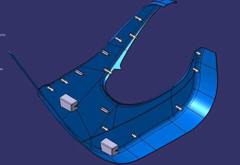
Lower Substrate
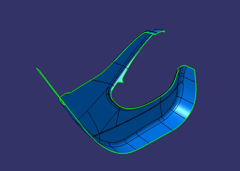
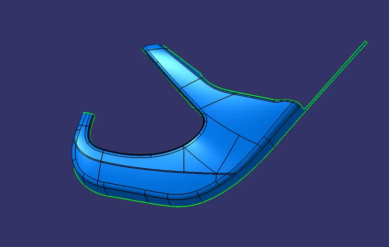
The thickness of the lower substrate is 2.5mm (from the given master section)
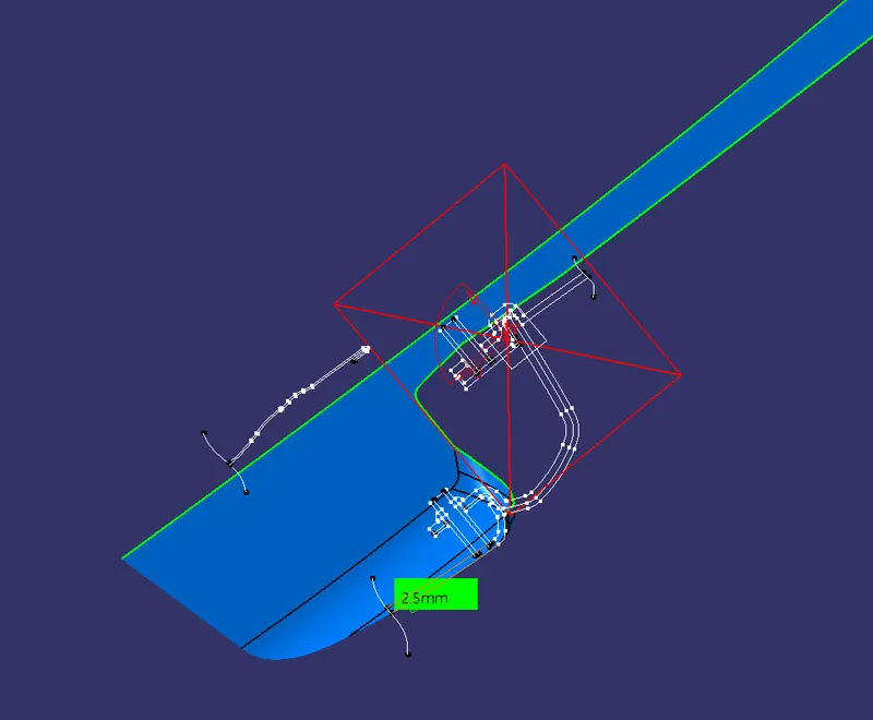
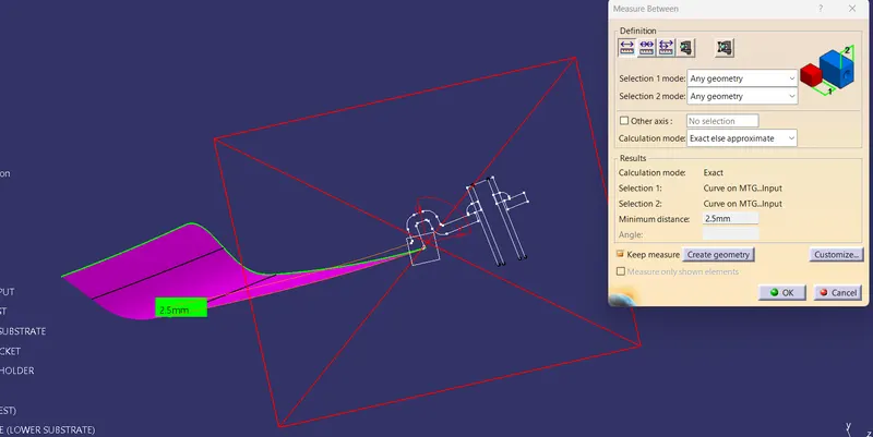
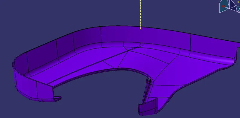
Map Pocket
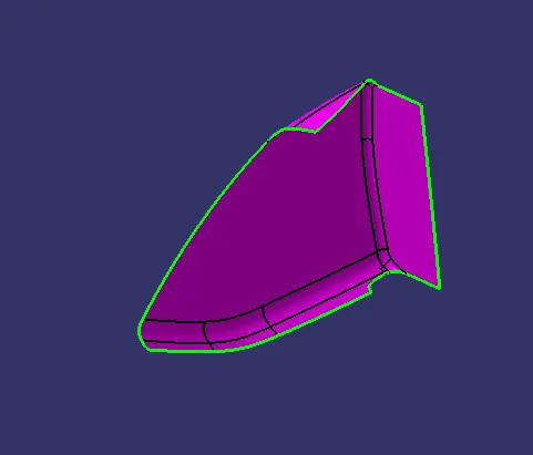
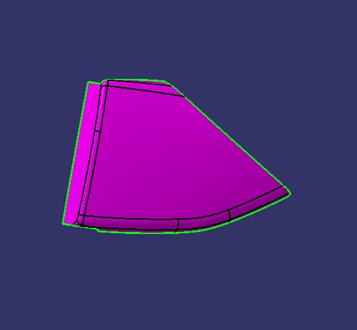
The thickness of the Map pocket is 2.5mm (from the master section)
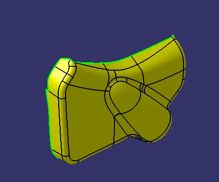
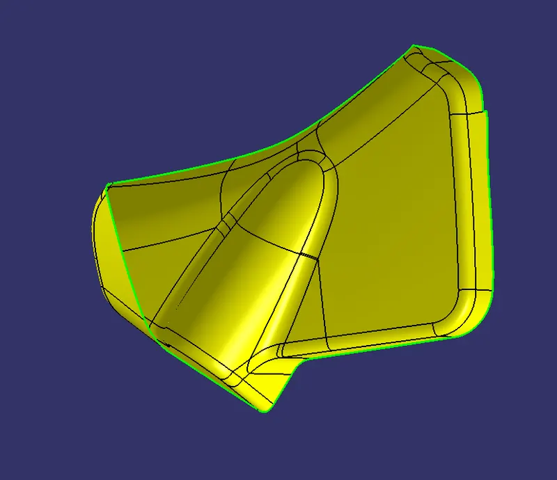
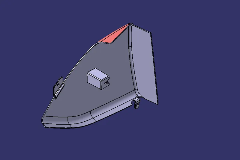
Bottle holder Class A
Report on Draft Analysis for Armrest
tooling Axis creation
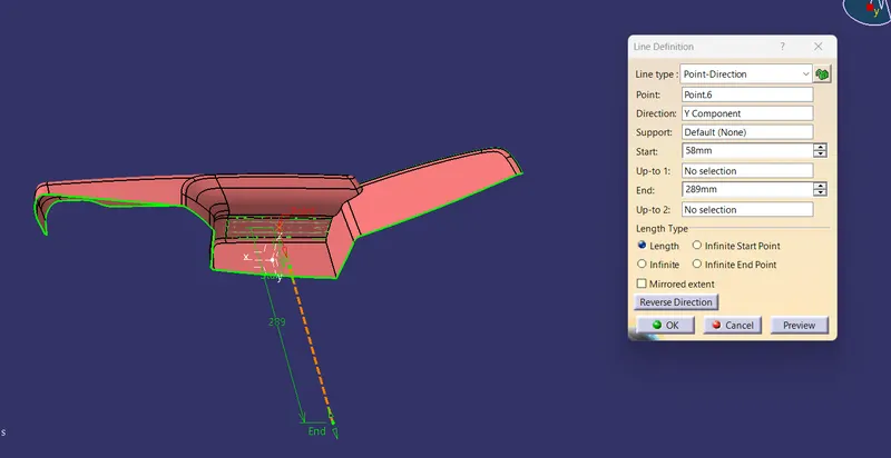
creating the main tooling axis using Bisecting method.
surface extraction and then interaction class a surface in x-z plan.
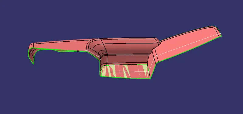
later created two lines on each side. and create a bisecting line between these two lines.
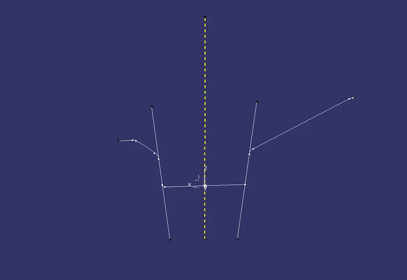
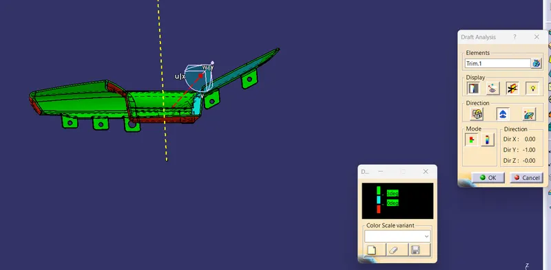
after we got the main tooling Axis we go for Draft analysis.
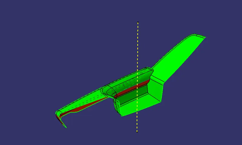
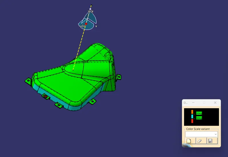
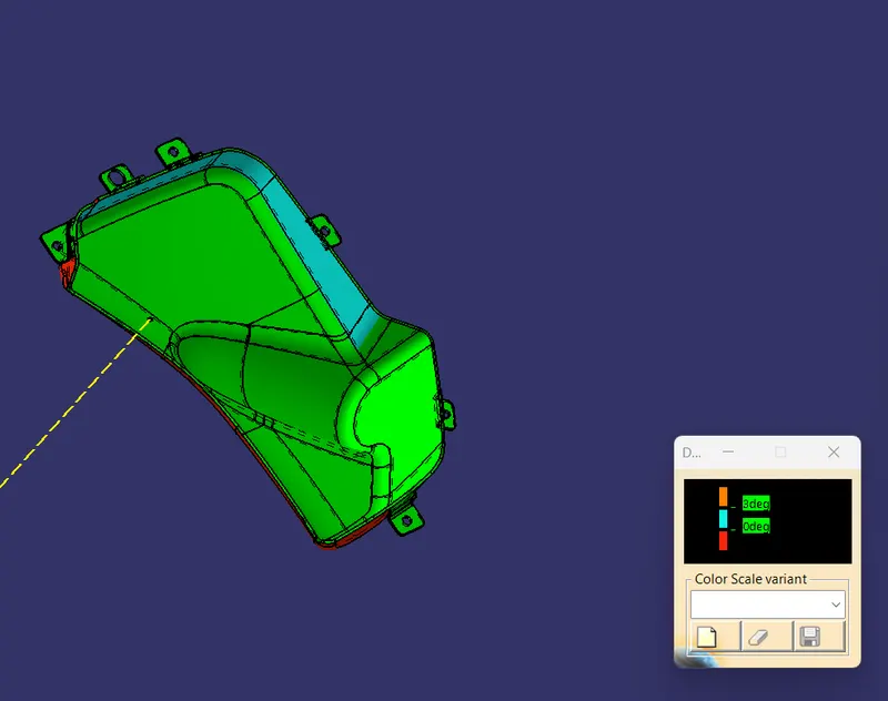
green area = clearing 3 deg draft
red area = less than 0 deg ( not clearing draft analysis)
this class A is not good. its needs to be reworked by the styling engineer.
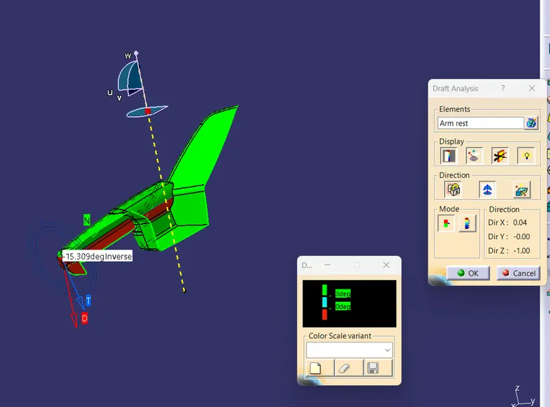
main tooling axis is not enough to complete this part. so I created a side tooling axis in the direction of Y
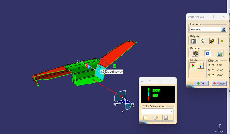
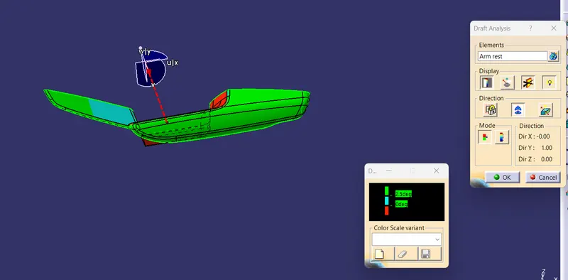
Draft Analysis for the Solid arm Rest with flanges
main tooling axis
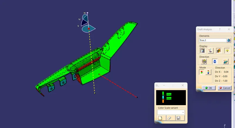
side tooling axis
Improve class A surface of the Armrest
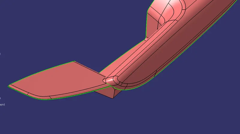
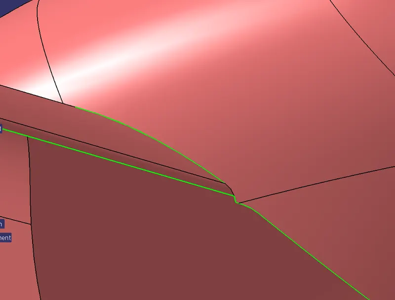
Class A surface of Arm Rest is not good it has some unwanted gaps and surfaces which can create problems during manufacturing so class a need to be improved (Usually this part is done by only a Styling engineer or you need permission for that to improve the surface) here we have permission for improving Class A surface for ARM REST.
problem
improved Class A
Extrate separately those area and extrapolate bottom area t
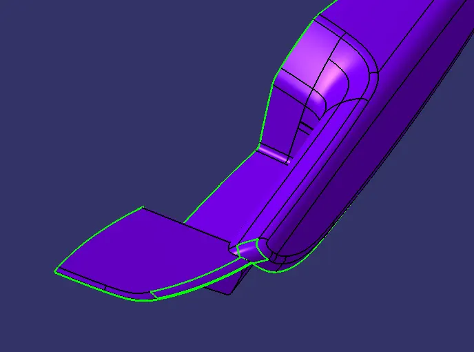
trim together
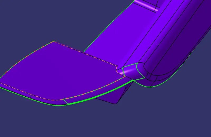
other area with extra surface I create a line and split it
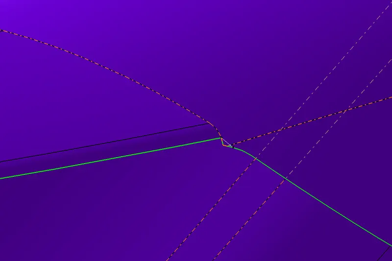
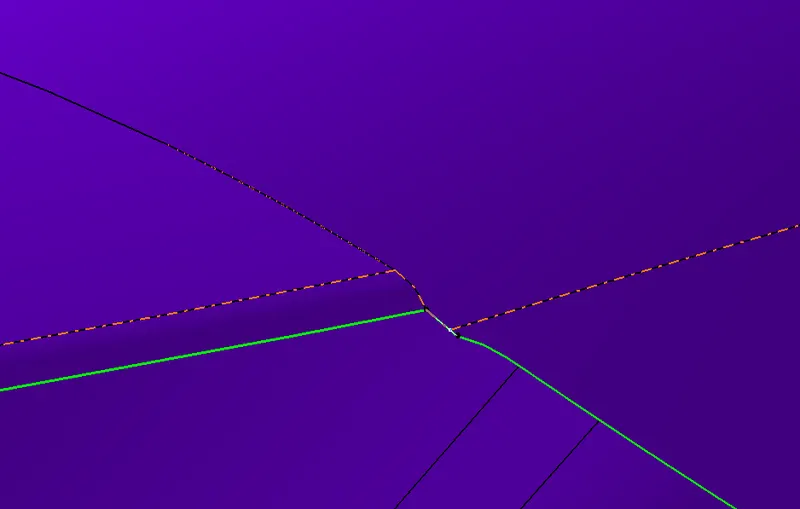
later Join
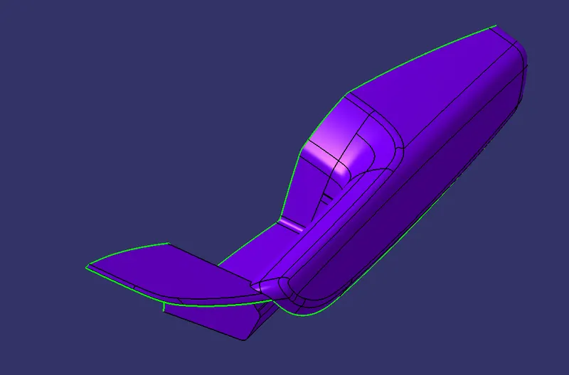
Class B creation
Offset 2.5 mm
during offset, these are some patches have not come properly.
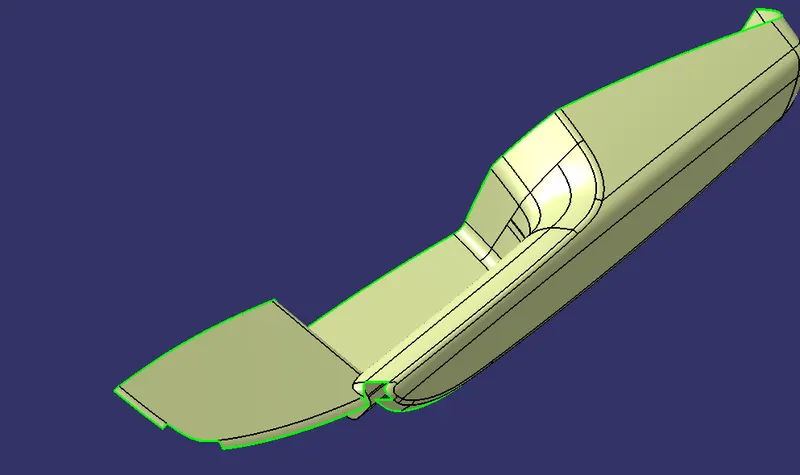
I extracted the area where patches are missing and untrimmed from class A. later offset 2.5mm then split with the boundary of the missing patch.
other are I go with multi section then join them together.
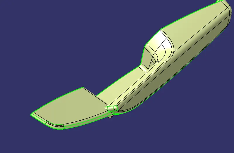
complete class B
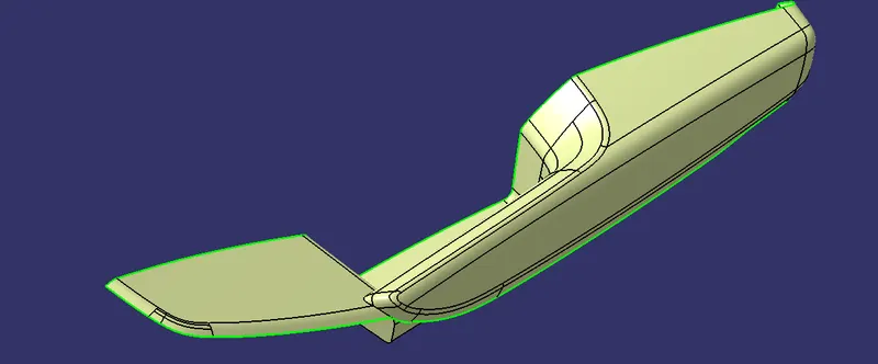
Class C creation
for class C creation, I identified the areas which are perpendicular to the tooling direction. there I go with a sweep in the draft direction. other with reference to the surface.
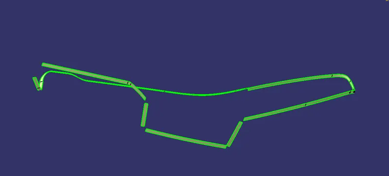
for joining these sweeps together I did multisection
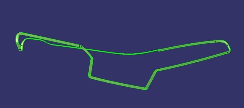
final Class C (join)
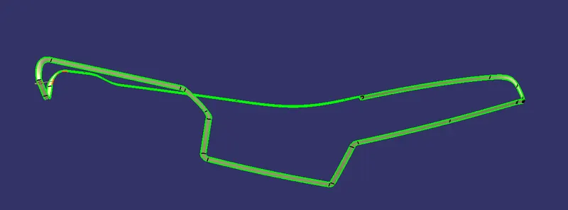
A+C
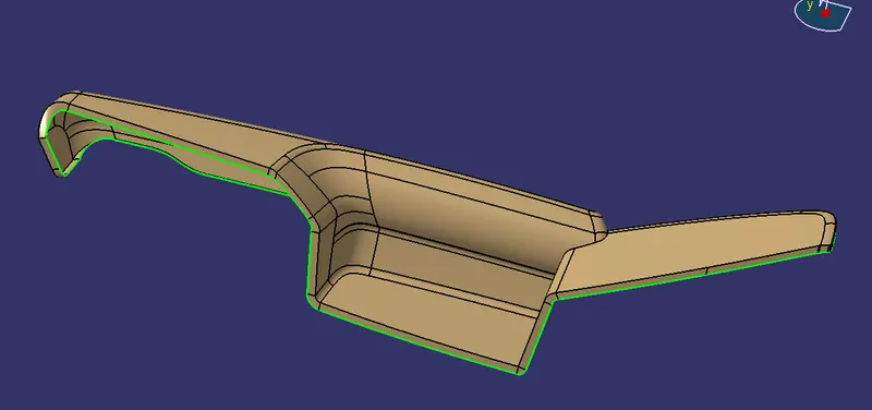
A+C+B
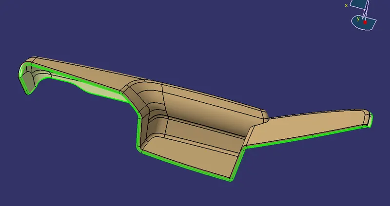
Close Surface AC+B
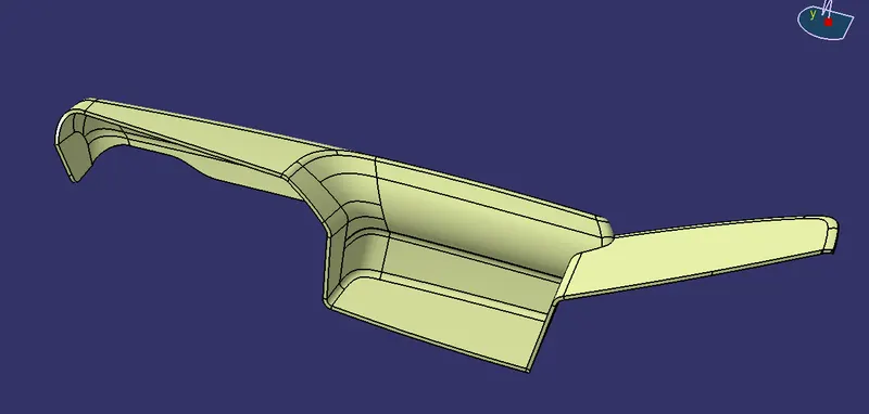
Lower Substrate
Report on draft Analysis of lower substrate
tooling axis creating- tooling direction of the lower substrate is along with the Y direction (visual Inspection). it is clearing the draft analysis in the y direction.
procedure- I extract the surface and then created a point in the center of that surface. later I created ling which is passing through the point in the Y direction. that is how I got the Main Tooling axis for the lower substrate.
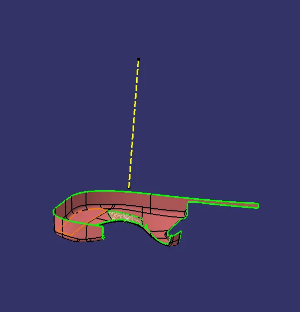
draft Analysis of the class A lower substrate-
clearing drat at 4.9 deg good to go
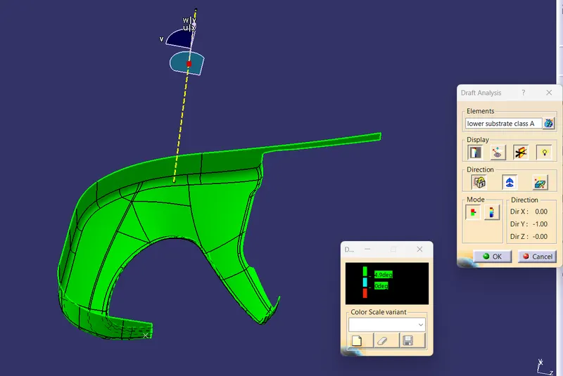
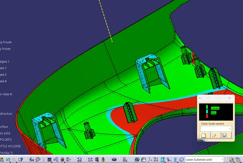
draft analysis of complete solid-
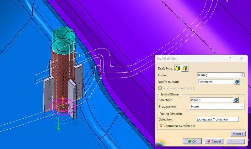
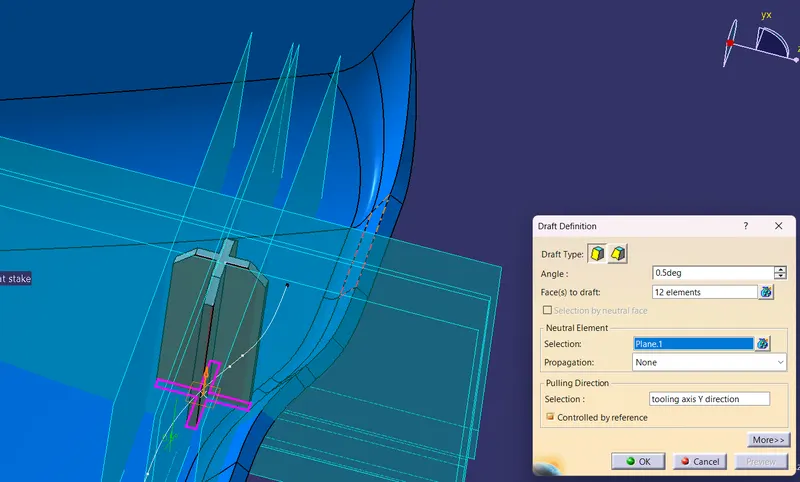
heat stake & locator having draft 0.5 deg
The dog house has 1.5 deg as per design rule
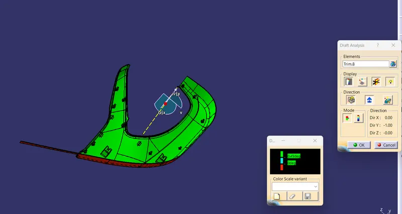
for the Dog house side core is a must for the side core tooling axis X direction is suitable.
0.45 deg is clearing dog house ribs
Class B creation
offset 2.5mm
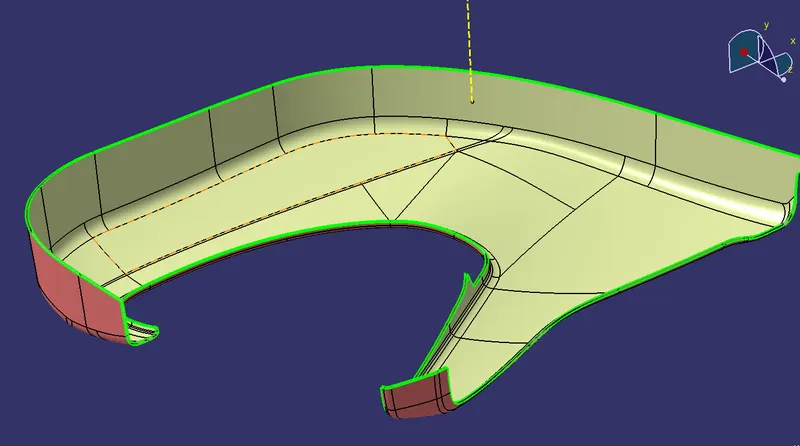
class C creation
class C has been created with the help of sweep with surface reference and draft direction sweep and multisection.
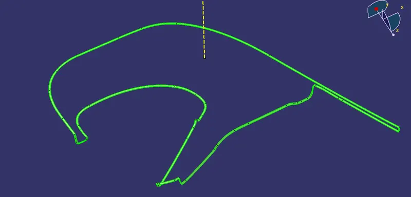
A+C
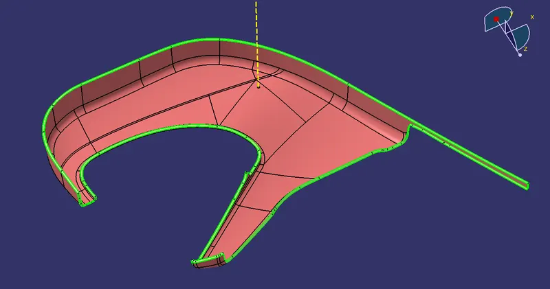
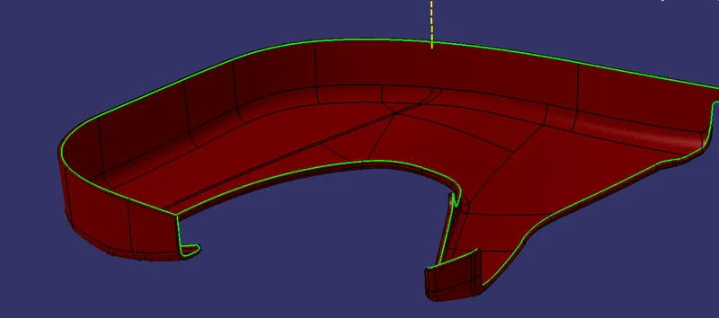
AC+B ( close surface)
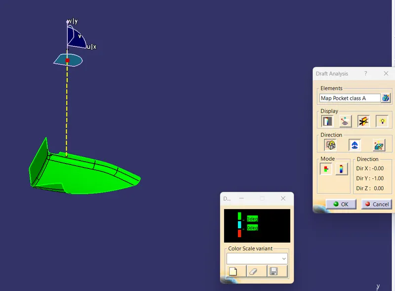
Draft analysis for Map Pocket
clearing draft 3 deg
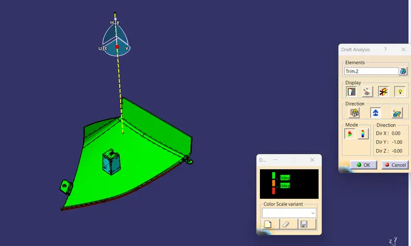
draft analysis for solid
the dog house has 1.5 deg draft
Class b creation
offset 2.5mm
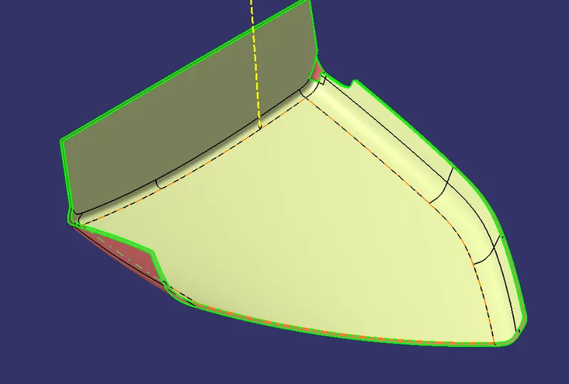
multisection
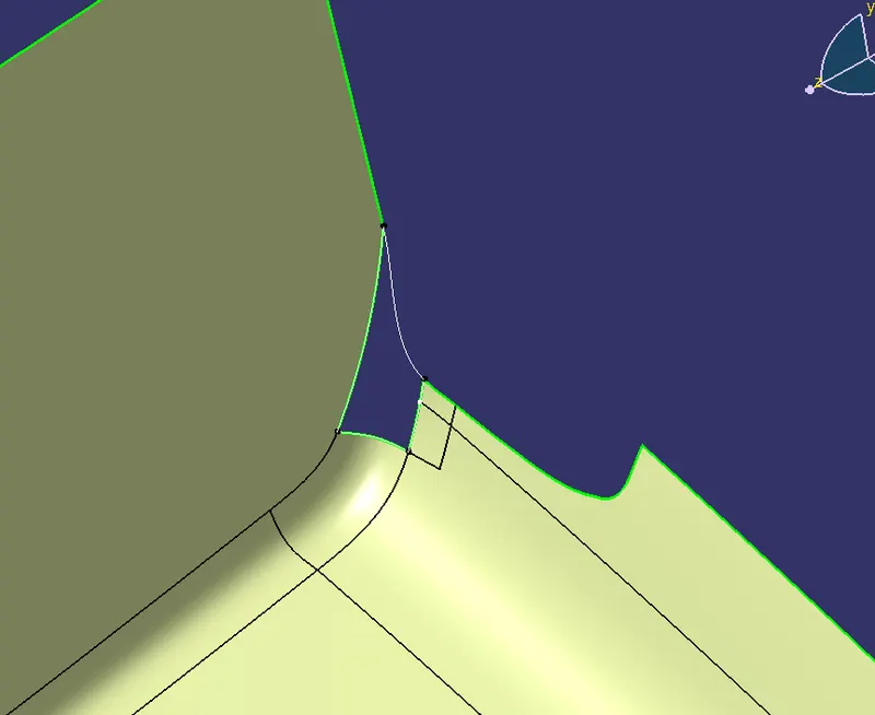
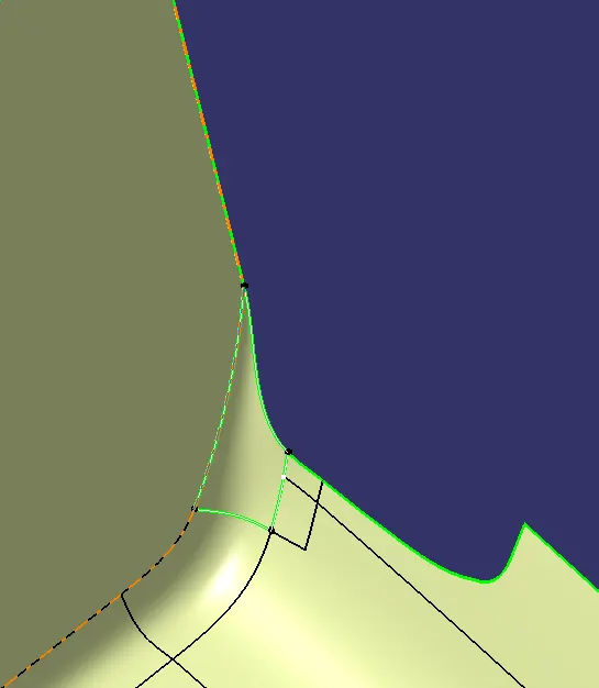
join
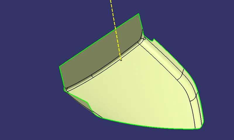
Class C surface
sweep with reference surface
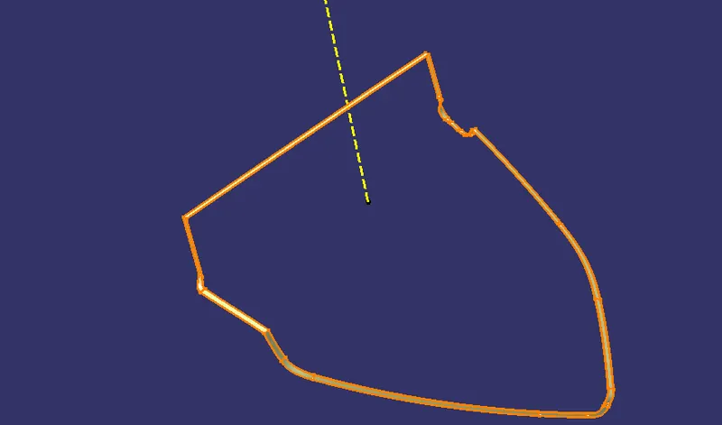
A+C
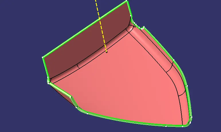
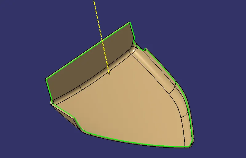
Close surface (AC+B)
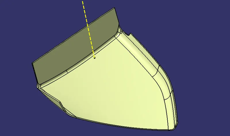
Draft analysis for Bottle Holder
The tooling direction of the bottle holder is in the Y direction
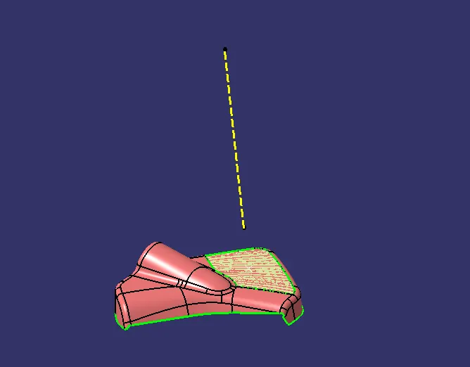
Draft analysis for the Bottle holder class A
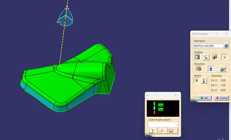
This Class is not clear with draft analysis at 3 deg.
class A must be improve By the Stying engineer
some are as 0 deg draft which is not acceptable
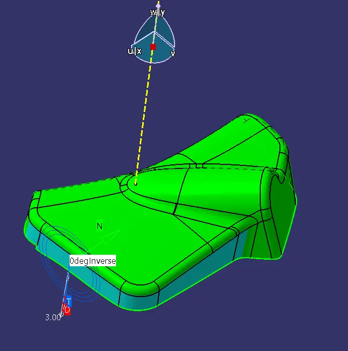
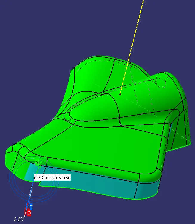
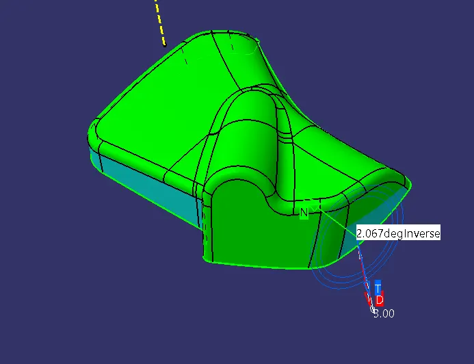
Draft Analysis for the Solid
because of the class A solid is also not clearing draft
Class B creation
offset 2.5mm
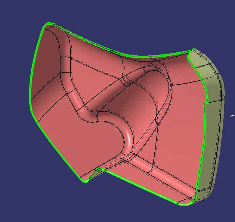
Class C surface
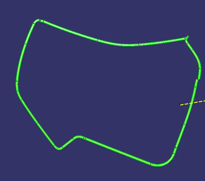
A+C
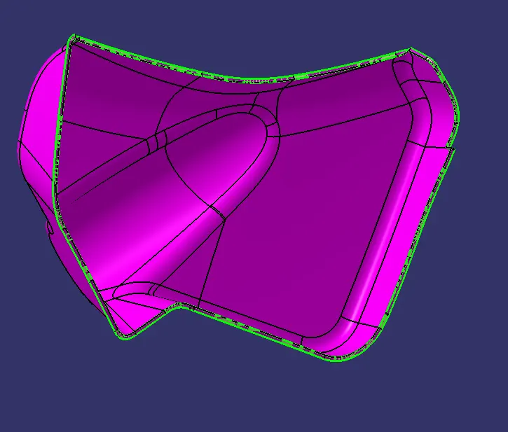
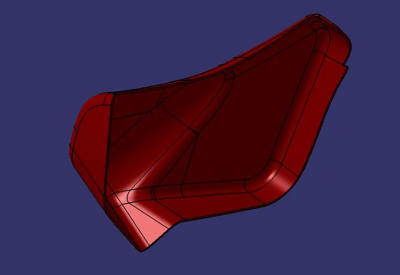
Close surface AC+B
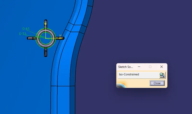
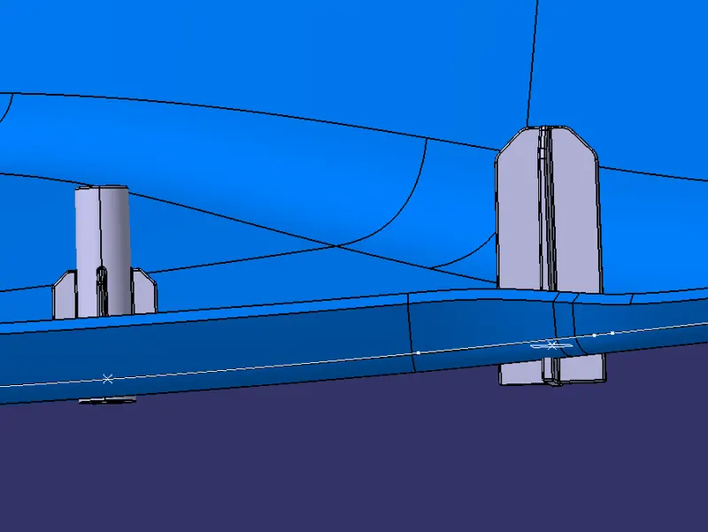
Heat stake creation
Heat staking also known as thermoplastic staking is the process of joining two dissimilar materials together.
heat stake has been created with the help of master section
ribs for heat stake
ribs are providing support for the flanges to rest on
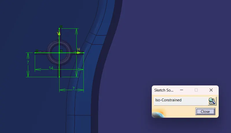
draft 0.5 deg
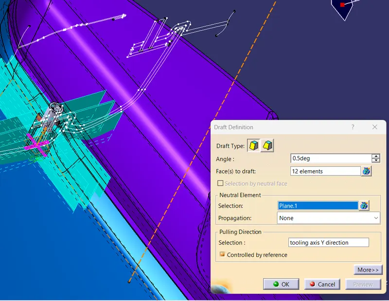
Locator
locator helps to locate the position
Flange creation
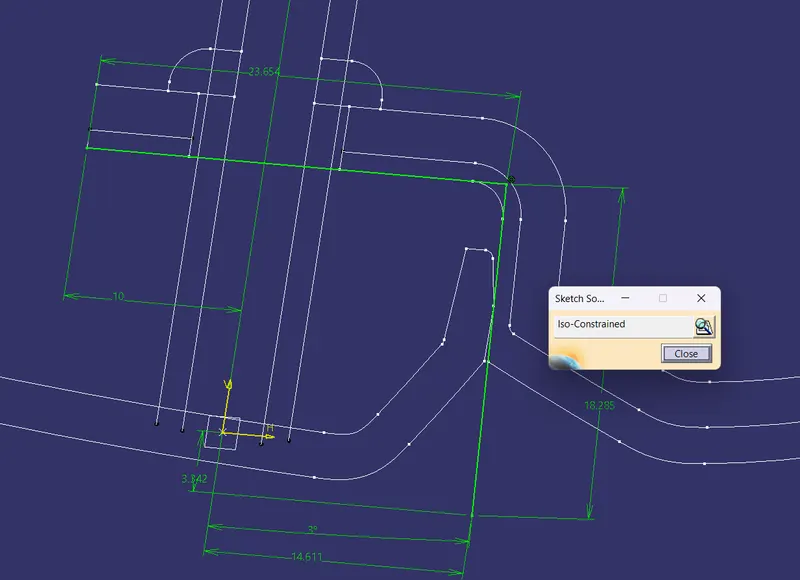
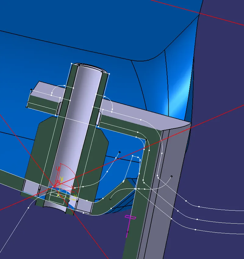
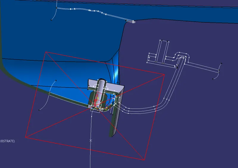
some flanges has been created with the help of master section
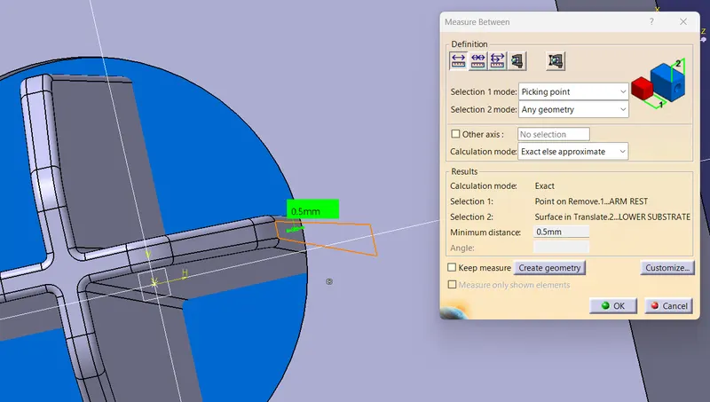
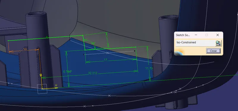
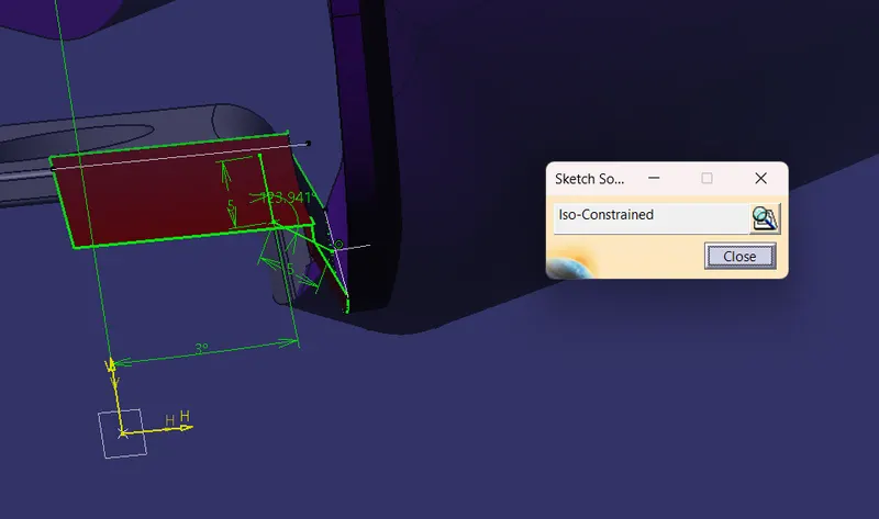
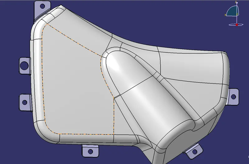
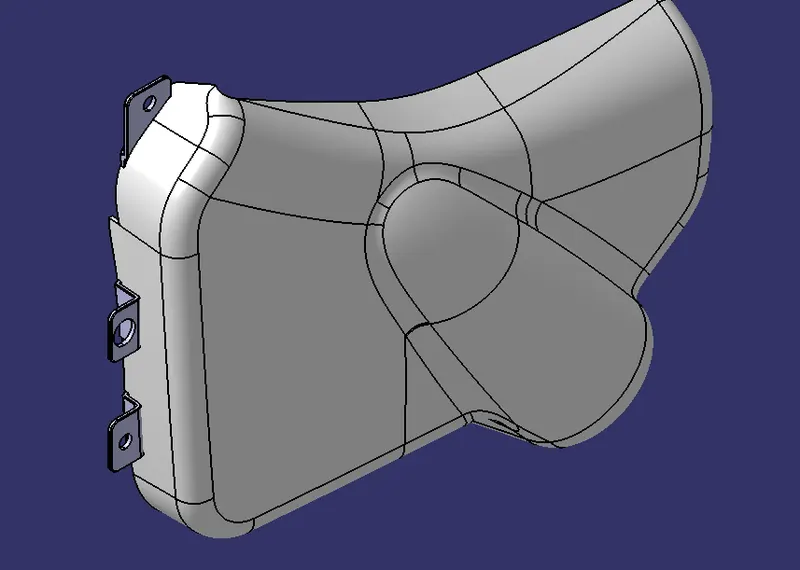
dog house
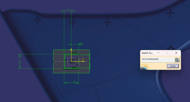
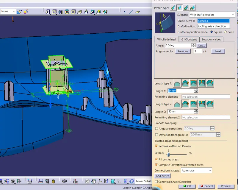
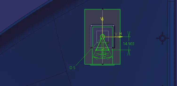
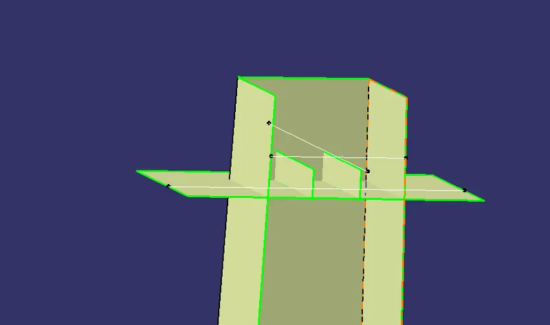
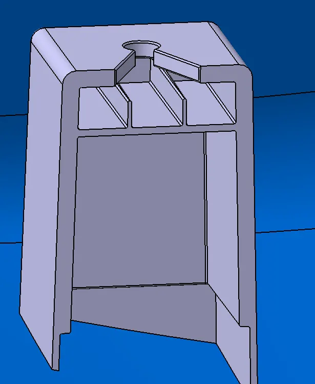
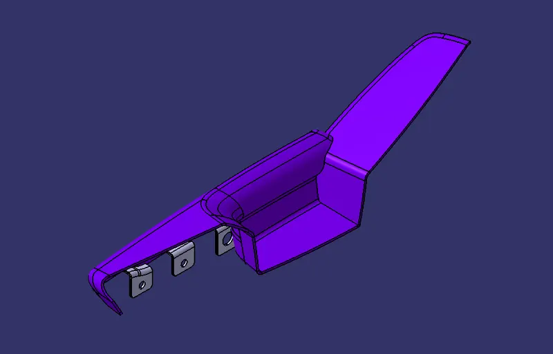
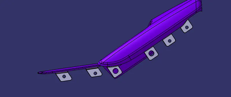
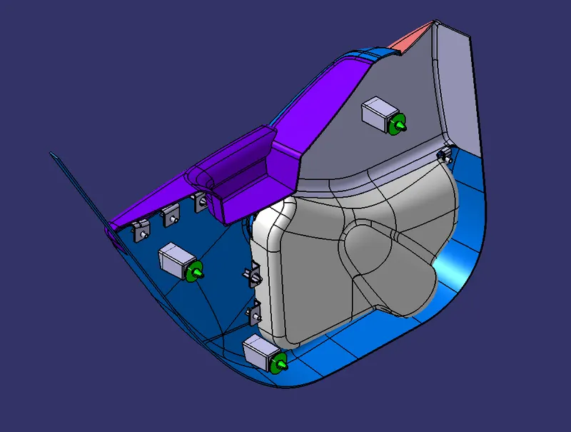
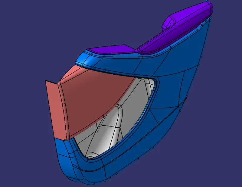
the final part with flanges, locator, dog house, heat stake
ARMREST
Lower Substrate
Map pocket
Bottle holder
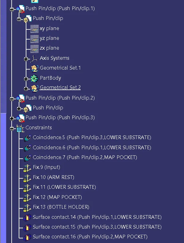
Push Pin
Front
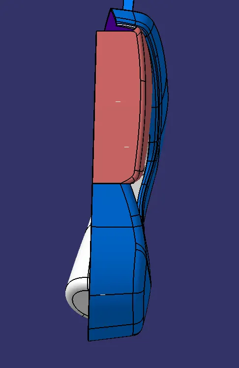
side
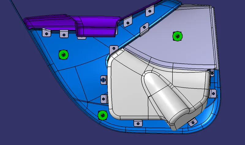
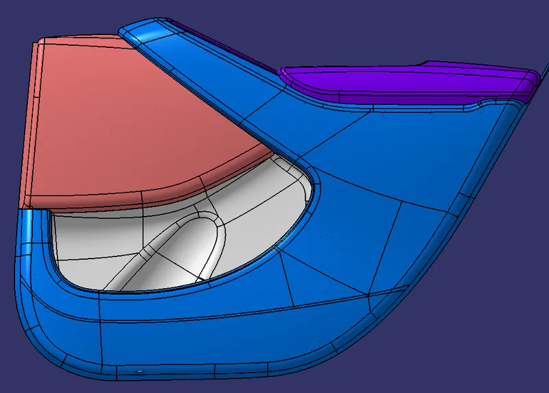
top
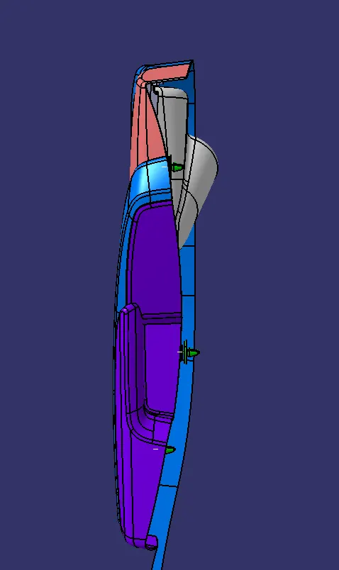
Iso metric
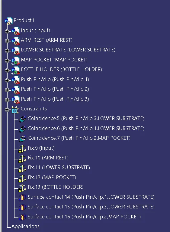
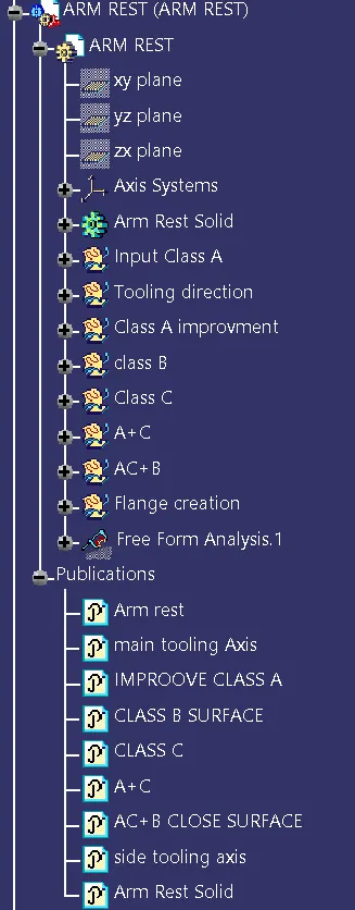
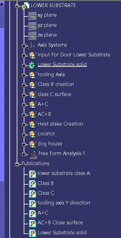
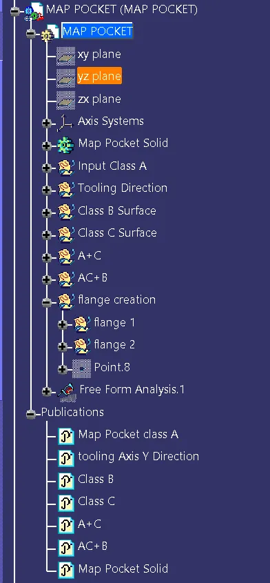
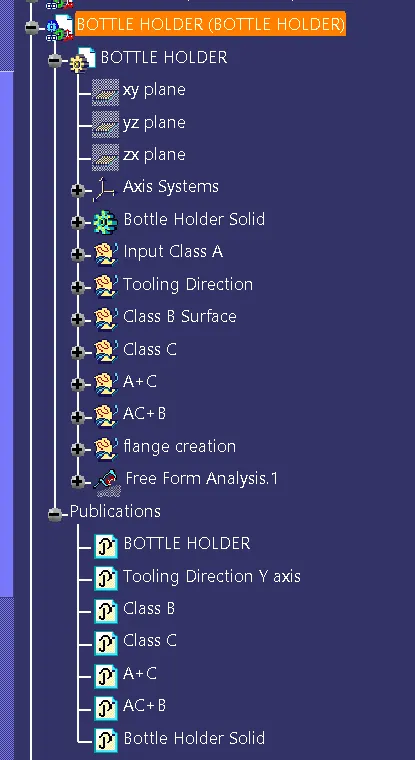
TREE