Week 12- Final project
Development of a Door Trim panel
Objective:
- a) Creation of side door trim panle from given class A surface. Apply thickness to it and use attachment features.
- b) Creation of flanges and heat stakes from given master sections.
- c) Creation of dog house and various attachment features using industry standards.
- d) Performing draft analysis and ensuring the features and surfaces clear it.
There is ten stages in automotive product life cycle developement. In this case our project is step 5 & step 6, that is New Product design and development. The objective is to design class B and class C surface from given class A surface and create a solid body from it using softwares like CATIA V5 taking into consideration the draft analysis which makes the component suitable for production using injection molding process.
Given Data :-
- Class A Surface for Door Trim Panel -
As we know in automotive industry there are complex products that we have to design but this is not possible with simple sketches for that we need Class A Surface.
The A-surface or the styling surface is first checked for any gaps and other issues in its surfaces. This Surface acts as the input surface so any correction to be done should be with approval from the styling team or done by them. A- perfect surface is the one when a boundary is created, the lines are only on the edges of a component and its holes or cutouts as shown below. 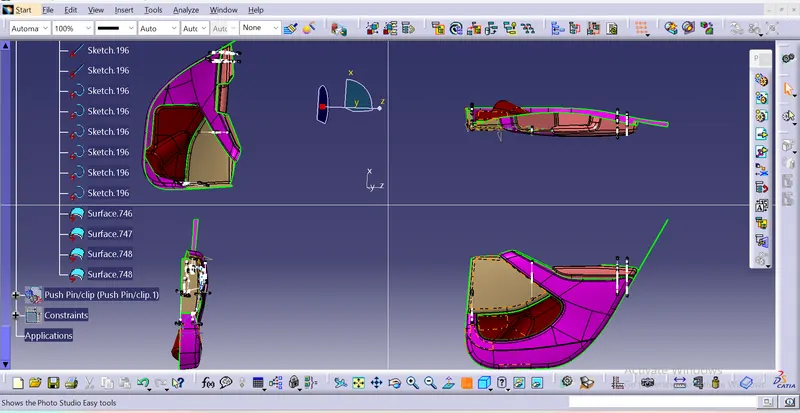
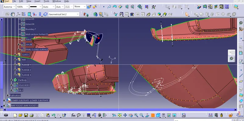
Inputs and Master section for Refrence to create the Flanges and Heat stakes .
Master Sections are the guides for design requirements which shapes the component after technical styling of Class A Surfaces.
Steps:
Given below is the procedure to create a new plastic component from given class A surface .
1) Creation of tooling axis
2) Creation of class B surface
3) Creation of class C surface
4) Creation of closed body
5) Draft Analysis .
Draft analysis is done to ensure that the designed part is manufacturable based on the draft conditions applied. It is done to ensure the proper ejection of the component from dies(for metals) or molds(for plastics). The basic idea is to ensure that the tooling axis has to be created in such a way that it has no parallel surface profiles of the component so that the ejection of the components can be ensured . Tooling axis is the axis along which cavity and core are closed and opened .
The main components of interior door panel of a car consists of the following parts .
1) Arm rest
2) Lower substrate
3) Map pocket
4) Bottle holder
Creation of tooling axis :-
Tooling axis: The direction in which the mold or core and cavity opens is the tooling axis. STEP-01. Connectivity of Class-A surface: Checking the connectivity of the surface, this can be done by creating boundaries or by simply using the join option such that any openings can be easily visualized.
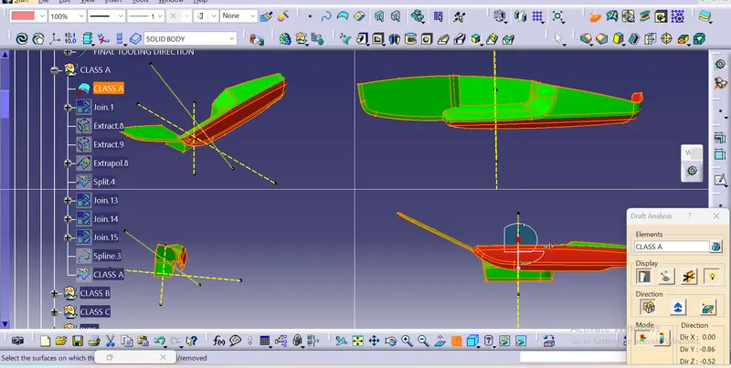
I have Created mutiple Axis to create a tooling direction finally i have clear with draft analysis here are the images to get clearify
Drafting Analysis:
The Draft Analysis allows the user to easily analyze a part for proper draft angle. A Draft Angle describes the amount of taper for molded or cast parts perpendicular to the parting line. Find the Draft Analysis in Tools tab. Draft Analysis is applicable for 3D part models.
Designers of plastic parts and mould tooling manufacturers can use the Draft Analysis tool to check the correct application of draft to the faces of their part. With draft analysis, you can verify draft angles, examine angle changes within a face, as well as locate parting lines, injection, and ejection surfaces in parts.
For this case as no hole is concerned, so we will try to consider the perpendicular axis of that dented curved surface, for creating the tooling axis. So we will analyse perpendicular plane.
By applying drafting analysis of 3 to 2.9 Deg, we can see all Surface is been cleared.
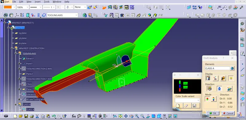
Armrest
- Class A Surface -
- Check Given Class A Surface Properly and check Quality of class A
- Create Tooling Axis for Class A
- Check for Draft Analysis for 3% to clear the Tool Test
NOTE :-
Found Class A surface has a Open boundaries and Qulaity is not good in this Case we have to Inform this to Styling Team for a better surface and Note we should never touch the Class A surface until styling team have asked to Repair it .
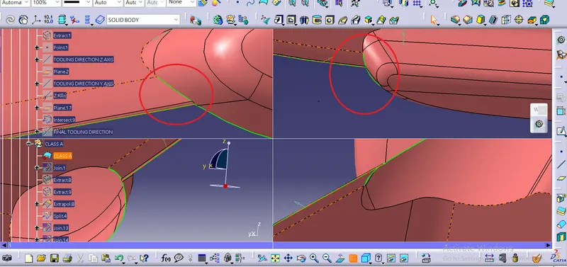
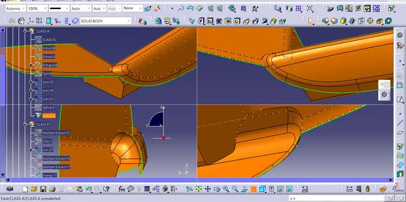
After intimating to Styling team.... (xyz) I have repaired the Class A surface to go further with Class B creation here are the images where we get to see the quality
Repaired Class A
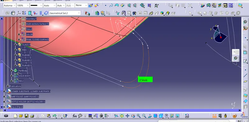
Create a class B surface:
- Class B surfaces are the secondary surfaces in plastic component design.
- In this model Class B-Surface is extracted from the A-surface and it is offset at 2.5mm in downward direction the thickness is consired by measuring master section inputs that 2.5 mm .
- The Given Master section has mentioned about the parameters Such as Thickness of the boby , Creating Heat stakes , Locators ,Flanges and Support Flanges.
Repaired Class B surface
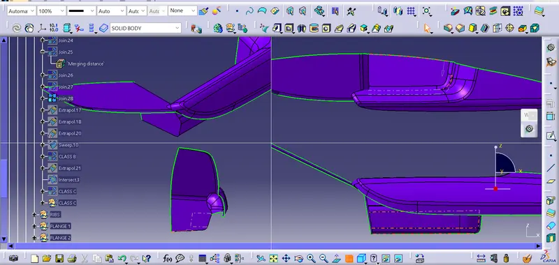
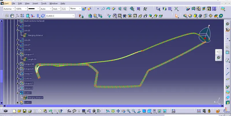
Create a class C surface.
- Boundry of the class A-Surface is swept along the tooling direction.
- C-Surface connects the class A-Surface and B-Surface. It is created using Sweep command.
- Class C is often specified for interior surfaces not readily visible, surfaces that will be covered by another part when assembled, or surfaces which the Customer feels do not need to meet a high cosmetic finish.
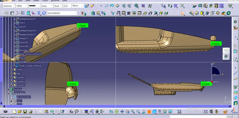
- Creation of Closed Body of Arm Rest
- By trimming join of Class A ,C with Class B surface we get close body.
Draft Analysis:
- The draft analysis technique is used to analyze whether our part model created in CAD is manufacturable based on the draft condition applied.
- Minimum draft angle is considered as 3 degree.
- step 1= enter part in Catia.
- step 2= Go to Material Mode.
- step 3= go for draft analysis.
- step 4= drag axis bar to the tooling direction of part.
- step 5= check for draft and make parting line as per analysis.
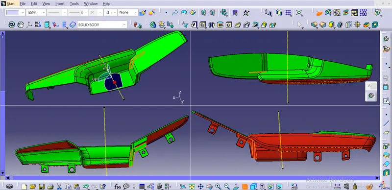
Here the images shows that the part is clearing Draft of 3 deg and is Manufacturable
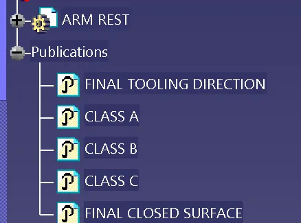
Publications of Arm Rest
Publications are used to make a particular geometry easily accessible from the specification tree. By using the required setting, only published elements can be used as an external reference if it is the requirement.
Lower Substrate
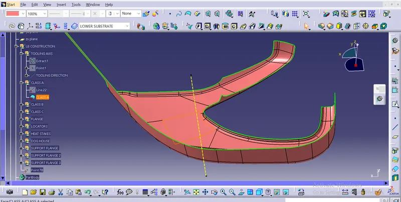
- Class A Surface -
- Check Given Class A Surafce for Quality, Any open Boundaries , Surface quality And Draft analysis .
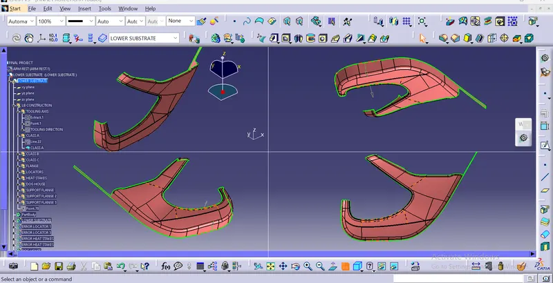
- Creation of Tooling Axis
- Try mutiple Tooling Axis to Make sure that the Surafce is clearing with minimum Draft Angle of 3 deg
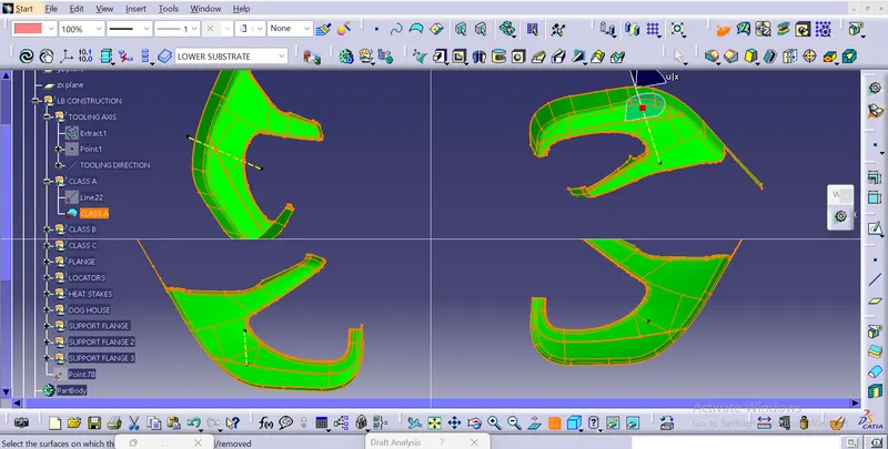
. Create a Draft analysis for Class A
- Here the images shows that the tooling direction is clearing the Draft angle and it is good to go with Class B Creation.
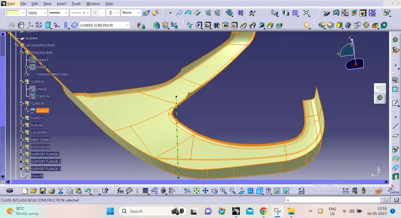
- Creation of Class B Surface
- Creating a CLASS B with offsetting the class A with 2.5mm
- Class B surfaces are the secondary surfaces in plastic component design
- There was no Error in offsetting the class A all the Surface are good to go with creation of Class C
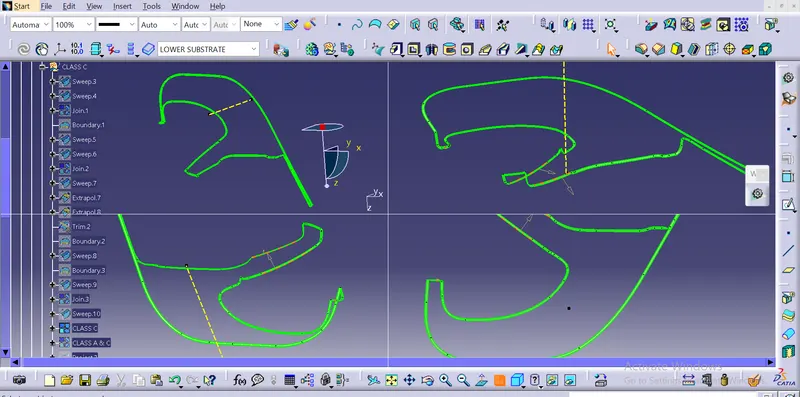
- Creation of Class C
- Class C is often specified for interior surfaces not readily visible, surfaces that will be covered by another part when assembled, or surfaces which the Customer feels do not need to meet a high cosmetic finish.
- C-Surface connects the class A-Surface and B-Surface. It is created using Sweep command.
- Boundry of the class A-Surface is swept along the tooling direction.
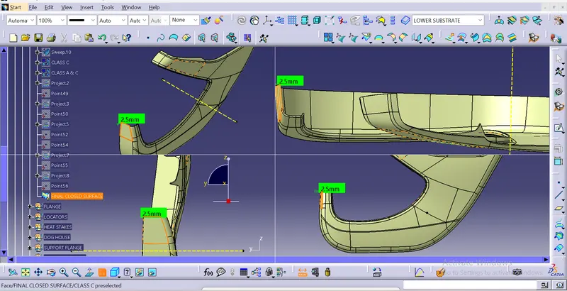
- Creation of Closed Surface of Lower Substrate -
- By trimming join of Class A ,C with Class B surface we get close surface .
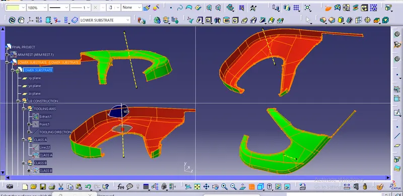
- Draft Analysis for Closed Body-
- The images shows that draft is good and can be Manufacture.
Creation of Heat stakes
- Heat Staking is a pulsed-heat process to join two or more parts out of which one at least is made of plastic.
- The process is to deform the plastic material using heat and force at a set process time.
- The bond is made by partially de-forming the plastic part in order to fix the other.
- Heat Staking makes it easy to bond metal to plastic and is commonly used in high volume/low cost applications such as automotive, IT and consumer appliances.
- Similar and dissimilar materials may be joined: metal to metal, plastic to plastic, metal to plastic
- Accurate control operating within a small process window
- Local heating resulting in no damage to surrounding materials
- Processing of glass-filled materials
- No mechanical vibration
- Many heat-stake shapes possible through custom designed tools.
- One of the important factor to be considered while designing the heat skates is the height of the heat skates. It should always be less than the height of the locators.
- Extract the surface that we going to create heat stake
- Use positiioned sketch and draw a heat stakes sketch
- Use pad commands for the sketch to till we required
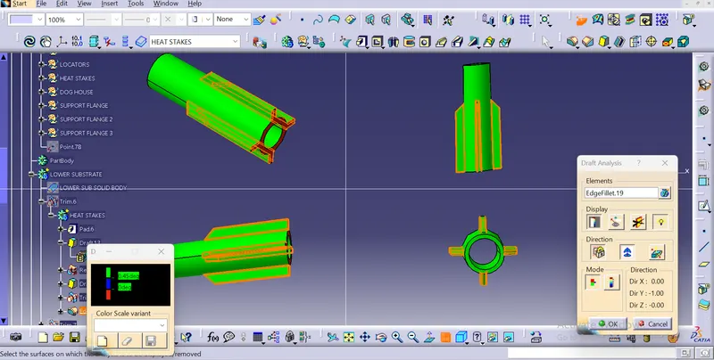
- Draft the stakes minimum of 0.5 degree
- Add fillet 0.5mm o all faces
- Assemble the heat stake to lower subtrate solid
- Maintain a 50 to 60mm between two heat stakes
- Translate the heatstakes to wherever we need
- Trim the all heat stakes with lowersubstrate solid
-
Sketch Plane is made in the tooling axis direction.
The length of heat stakes should be at least 5 mm lesser than locators, L = 15mm
Radius, ID = 5mm, OD = 7 mm
Draft Angle = 0.5°
RIBS
- The ribs provide economical stiffness and strength to the part without increasing the overall thickness of the part.
- The ribs are used as locating and arresting in the assembly as locators.
- Proper allignment in mating parts, slot and rib pair is long lasting other than screw pair which loosen up with time.
- Acting as stops or guide for mating the tilted headlamps.
- Rib designs includes.
- thickness, quantity, height , manufacturibility and location.
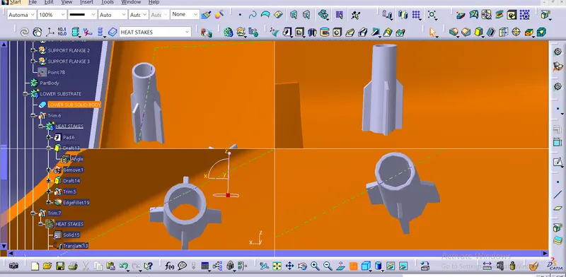
Draft Analysis of .45 deg for Heat stakes
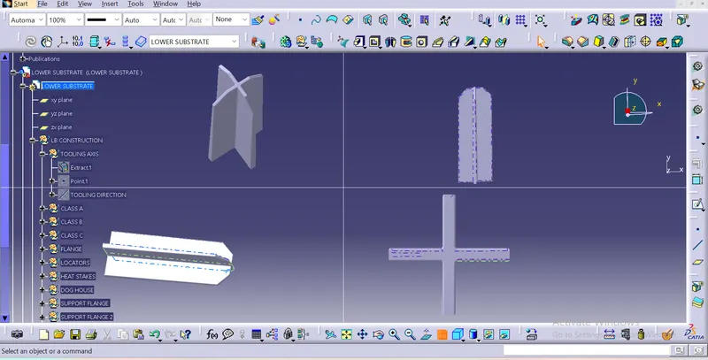
Creation of Locators
LOCATORS -
- The main purpose of locators is to facilitate proper locking of two components together while assembling and arrest the maximum degrees of freedom possible.
- These locators are similar to guide pins provided in mould.
- The two types of locators used are two way locator and four way locator.
- We have positioned three 6 way locators in our model which meet the rib design criteria.
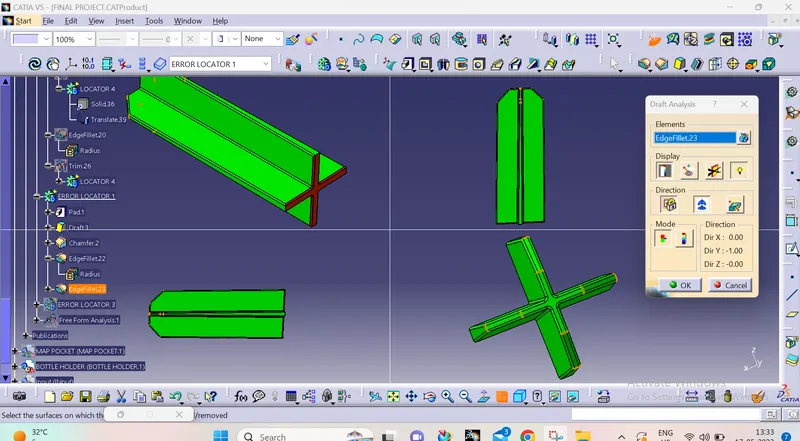
Draft Analysis 0.45 deg for Locator
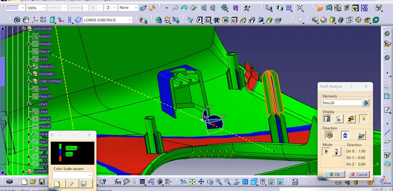
Sometime the draft of 0.5 deg does not work so we have to try with 0.45 deg to get draft clear .
Creation of Flange
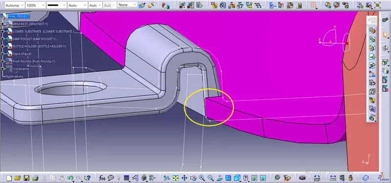
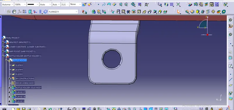
- Flange are used to connected between two or more parts accordingly with heat stakes.
- Flanges and heat stakes have to created at same location to fix the parts each other permanently.
- Flanges Top surface have to be straight there should not be Uneven surface so the core and cavity will remain same for all the flanges and will cost us less during manufacturing .
- Flange Should be created with reference of Tooling direction.
- There should be at least 50 to 60mm gap between two parts .
- The hole at center will be guided along the heat stakes.
- Later top portion of the heat stake will be melted over it.
- The flange should rest on the supporting ribs on side .
- Make a hole exactly at center so that heat stakes can fitted properly maintain 0.5 clearance .
Creation of Dog House
DOG HOUSE -
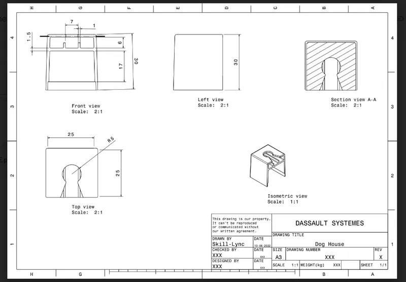
- The two main purposes of a dog house are to avoid sink marks and to house various other engineering features like screw boss, locators, push clips etc.
- In this case, the dog house is designed to house the push clips and the 4 way locator. The dog house designed for the push clip features a slot on the top face to accommodate the push clip
- The dog house should follow certain design rules which are stated below
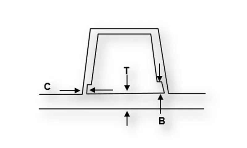
- Doghouse wall thickness at the intersection of the part wall (C) should be 40% or less than the main wall stock (T).
- The height of ( B ) should be between 3.0 – 6.0 mm
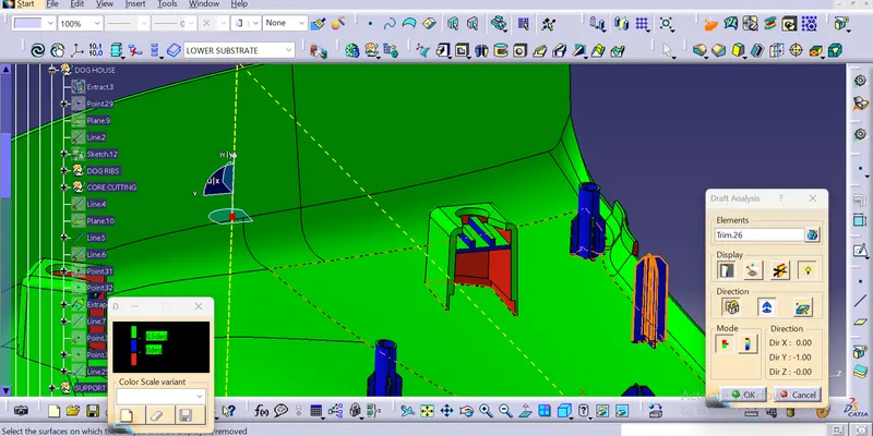
- Outer surface of dog house must have a draft angle of 3 degrees
- Inner surface of dog house must have a draft angle of 0.5 degrees
Draft Analysis of maintooling axis
Draft Analysis of Side tooling axis
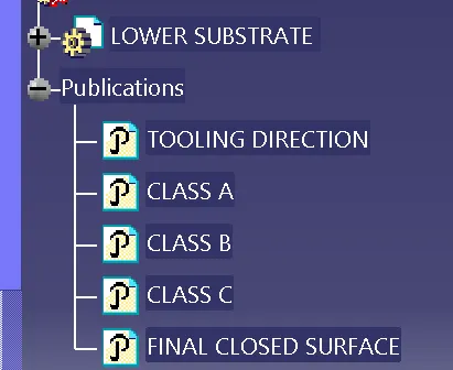
Publications of Lower substrate
Publications are used to make a particular geometry easily accessible from the specification tree. By using the required setting, only published elements can be used as an external reference if it is the requirement.
Map pocket
- Creation of Tooling Axis
Create a Tooling axis so that it should clear the draft of 3 to 2.9 deg.
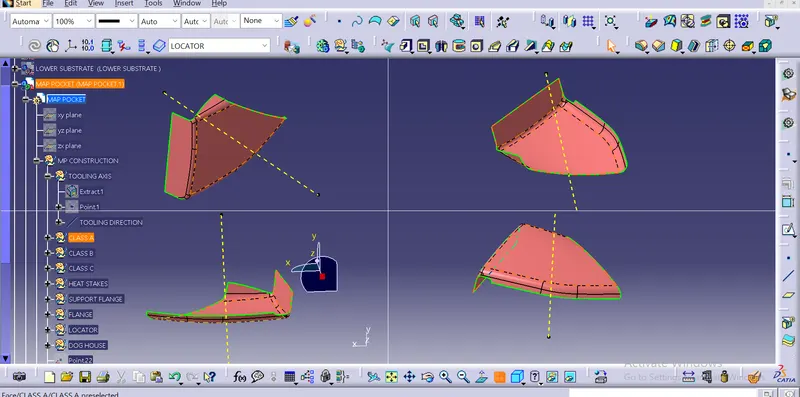
The image shows that the Draft is clearing of 2.9 deg .
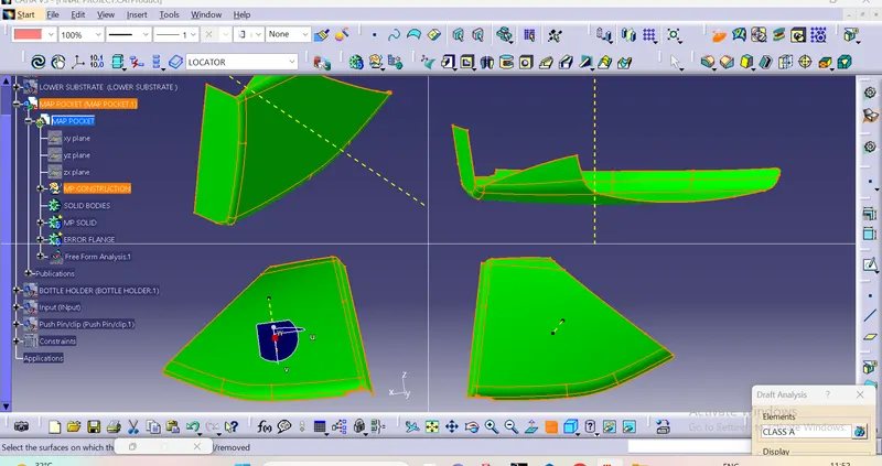
- Class A Surface -
- Check Given Class A Surafce for Quality, Any open Boundaries , Surface quality And Draft analysis .
- There is no open Surface and the Quality is good to create Class B
- Class B Surface
A. To Create Class B we have to offset Class A for 2.5mm
B. We Found Some Surface is not open gaps so we have to improve the Class B by Operations tools And Surfaces Tools to clear the Gaps .
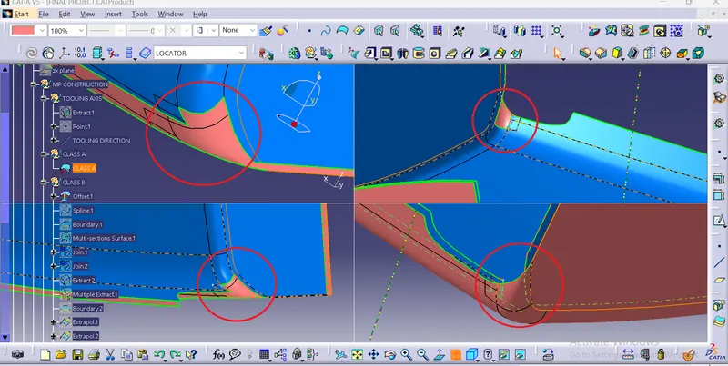
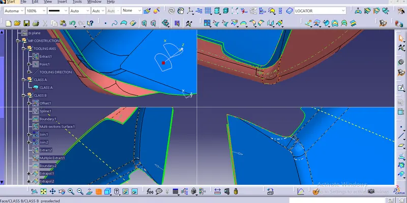
After Trying Mutilple Operations we finally got a good Class B surface
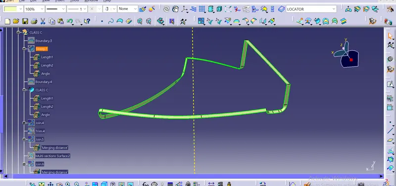
- Creation Of Class C Surface
- Class C is often specified for interior surfaces not readily visible, surfaces that will be covered by another part when assembled, or surfaces which the Customer feels do not need to meet a high cosmetic finish.
- C-Surface connects the class A-Surface and B-Surface. It is created using Sweep command.
- Boundry of the class A-Surface is sweep to create Class C with refrence of Surface with 90deg .
- Creation of Closed surface
- By trimming join of Class A ,C with Class B surface we get close surface .
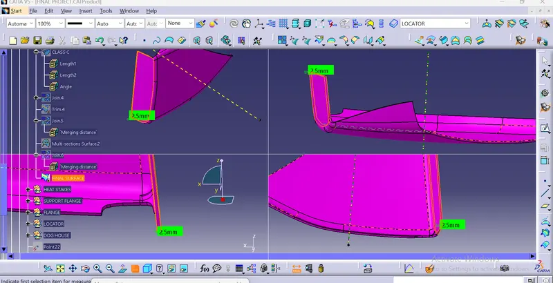
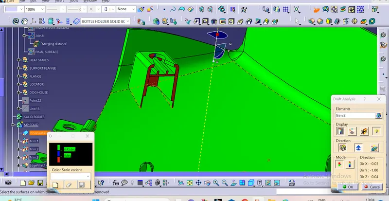
- Draft Analysis for Map Pocket
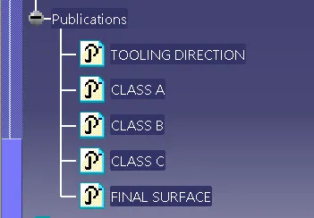
Publications of Map Pocket
Publications are used to make a particular geometry easily accessible from the specification tree. By using the required setting, only published elements can be used as an external reference if it is the requirement.
Bottle Holder
- Creation of bottle Holder
- Create a Tooling axis for given Class A in such a way of clearing draft Analysis of 3 to 2.9 deg
- Here i have Created two Tooling direction but it could not clear some surface as shown in images
Tooling axis one
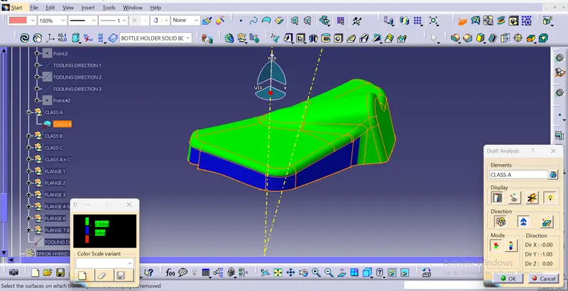
Tooling axis two
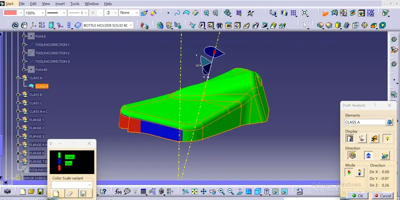
From above draft analysis we notice that some area are not have minimum 3 degree darft. Blue colour area shows negative draft for that we have to informed styling team for improvement in class A .
- Class A Surface -
- Check Given Class A Surafce for Quality, Any open Boundaries , Surface quality And Draft analysis .
- There is no open Surface and the Quality is good to create Class B
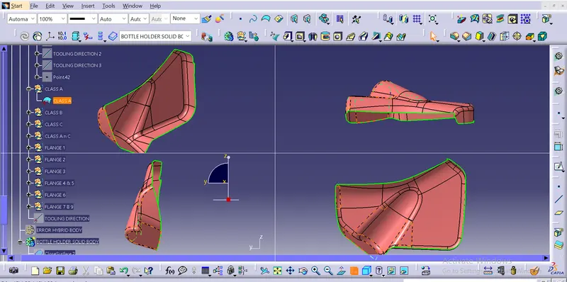
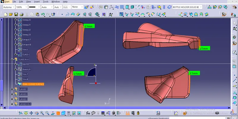
- Creation of Class B Surface
- Creating a CLASS B with offsetting the class A with 2.5mm
- Class B surfaces are the secondary surfaces in plastic component design
- There was no Error in offsetting the class A all the Surface are good to go with creation of Class C
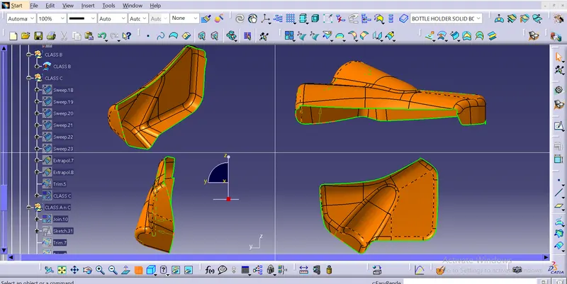
- Creation of Class C
- Class C is often specified for interior surfaces not readily visible, surfaces that will be covered by another part when assembled, or surfaces which the Customer feels do not need to meet a high cosmetic finish.
- C-Surface connects the class A-Surface and B-Surface. It is created using Sweep command.
- Boundry of the class A-Surface is swept along the tooling direction.
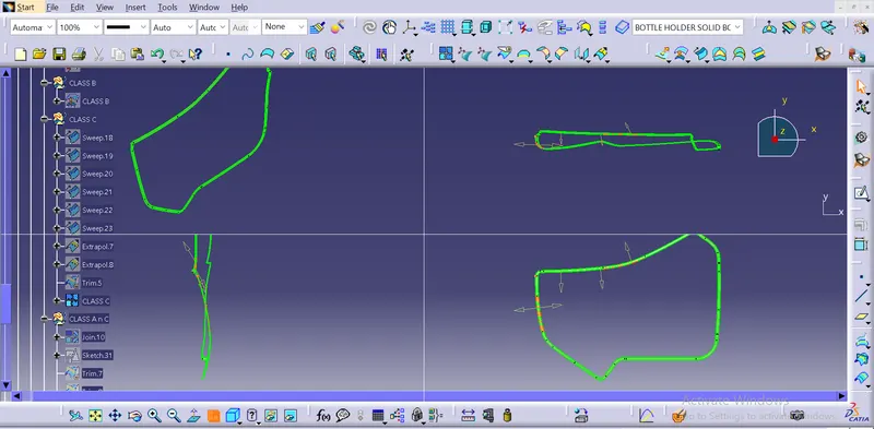
- Creation of Closed Surface of Map Pocket -
- By trimming join of Class A ,C with Class B surface we get close surface .
Draft Analysis of Bottle holder
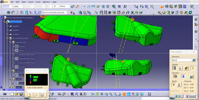
From above draft analysis we noticed that bottle holder part is not as per requirement. It is not manufacturable because at some area it have negative draft for that we have to informed styling team.
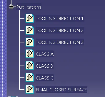
Publications of Bottle Holder
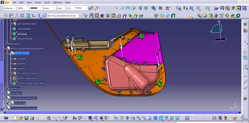
Publications are used to make a particular geometry easily accessible from the specification tree. By using the required setting, only published elements can be used as an external reference if it is the requirement.
Final Assembly :-
The below image shows the entire assembly of the Door Trim Panel complete work after attaching the Push Pins given