Week 12- Final project
DOOR TRIM PANEL CREATION REPORT
AIM: To create the door trim panel by the given inputs.
First I created the product file then I assembled them separately into that product file by using the assembly workbench. Then I saved the product file and also propagated the directory in a single folder. This door panel consists of four parts,
1. Lower substrate
2. Map pocket
3. Armrest
4. Bottle holder
5. Pushpin
@CREATION OF LOWER SUBSTRATE:
1)Class A: The class A surface is given as input.
The tooling axis is created in the Y direction.
2)Class B: To create class B I offset the class A for 2.5mm. Then Class B surface is created.
3)Class C: To create class C first I created the boundary of class B and then sweep it. Then I got surface c as an output. Now I joined the surfaces A and C together.
4)FINAL TRIM: To create a closed surface, first I intersected surface B and join of surfaces A, and C. So I can see clearly whether the gaps are creating problems between the two surfaces. I got gaps between surfaces so I used to extrapolate the surfaces a little more and finally, I got a closed boundary. Now I trimmed both surfaces together.
5)CLOSED BODY is created by using the close surface option in part design.
6)B SIDE ENGINEERING FEATURES are created.
1)HEAT STAKE AND SUPPORTING RIBS:
By taking reference from the master section I created the point by using between options and created the inside dia as 4.5mm and the outside dia as 7.5mm. Now create a sketch and create a pad, draft, and radius to it. Also, create another sketch, and ribs are created in it I created a pad, draft, and radius to it. Now create the body and add the heat stake and by using union trim we can clear the inside area of supporting ribs together. Now we can translate these into required points. before translating I create the parallel curve by using the master section as a reference. so I created a repetition point option and created points on it.
2)LOCATORS:
create a sketch and then use pad, draft, and fillet commands. Here is created, a four-way locater. Then translate these locators into required positions. then create the body and assemble these locators. then union trims them with the main body.
3)DOGHOUSE:
In this project, I created a dog house by using a part design workbench. create the sketch to the required dimension, then pad it and create the draft for both the main and side tooling axis. then create a fillet for it. Create another body and copy the same for coring creation. now first dog house is shelled for 2.5mm. the top portion is created .now use the coring body by creating a plane and use that to split the body .so here is used 6mm is to split the body and then add a fillet to it. then remove the coring with the main dog house. Also, I created the ribs inside the dog house by creating a sketch and using a pad, draft, and fillet to it and union trims them with the main dog house. Also, I created the top profile sketch and extruded it to make a split with a dog house for the support of push pins. so make a copy of the doghouse and paste it to the required positions. finally, union trims with the main body.
4)FLANGES: following master sections the angle and values are noted.
1. create a point and plane
2. then extract the surface from the final trim and not from the solid part. also, create a boundary to the extracted surfaces.
3. then take the intersection between the plane and extracted surface.
4. create a sketch to create the vertical line.
5. Also, create a sketch to create the horizontal line.
6. sweep the vertical line with the reference surface option and the draft angle is 0.5deg. Then extrude the horizontal line. Then trim both surfaces and create a thickness of 2.5mm at it. then take the horizontal line and make a sweep with the draft direction and the draft angle is 0.5deg.
7. now offset the swept surfaces on both sides to the required values. then finally split them to create the flange. also, apply fillets to it.
8. Then create a sketch for the hole and use pad, draft, and fillet to it .then remove this with the main flange.
9. clearance for the flange and heat stake is 0.5mm .also, clearance for the flange and locater is 0.5mm.
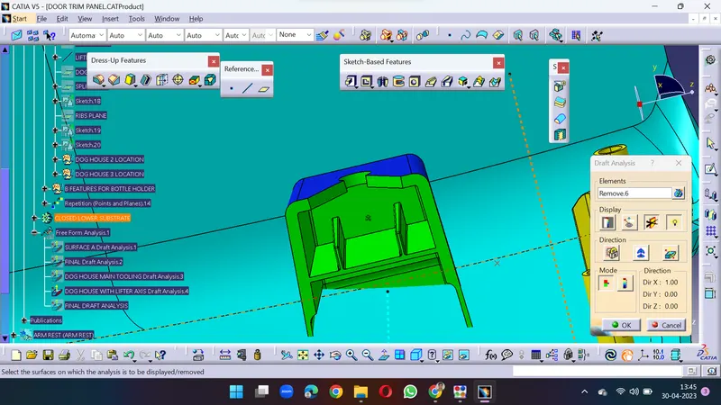
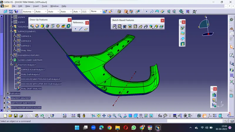
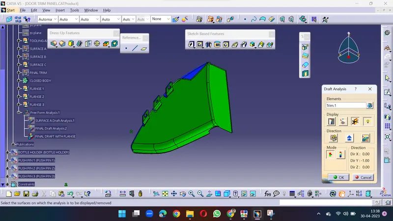
Then finally we need to take a draft analysis for surface A and the final component.
Now the lower substrate is completely created.
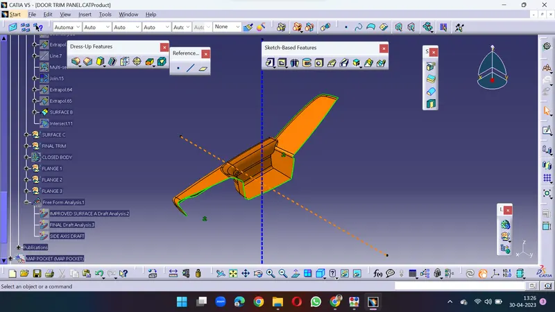
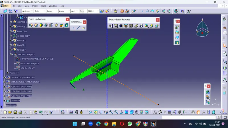
@ARM REST CREATION:
1)CLASS A: Class A is given as input. but the surface quality is not good.so I changed the surface to create a completely closed and to check it I took the boundary so now I got a closed boundary.
The tooling axis is created in the Y direction.
2)CLASS B: to create class B offset the class A to 2.5mm. here I got some open area. I closed them by using a multi-section solid. also, I removed some sharp edges by creating a spline and trimming them.so I got surface B as a result.
3)CLASS C: is created by taking the boundary of surface A and using a sweep with draft direction and reference surface to create it. Then join surfaces A and C.
4)FINAL TRIM: first we need to check the surface by using the intersection method.so, I got some open boundaries and closed them by extrapolate option and then trim the surface with B.FInally we got a closed surface as a result.
5)CLOSED BODY: By using the close surface method I closed this Final trim.
6)FLANGE CREATION: Following master sections the angle and values are noted.
1. create a point and plane
2. then extract the surface from the final trim and not from the solid part. also, create a boundary to the extracted surfaces.
3. then take the intersection between the plane and extracted surface.
4. create a sketch to create the vertical line.
5. Also, create a sketch to create the horizontal line.
6. sweep the vertical line with the reference surface option and the draft angle is 0.5deg. Then extrude the horizontal line. Then trim both surfaces and create a thickness of 2.5mm at it. then take the horizontal line and make a sweep with the draft direction and the draft angle is 0.5deg.
7. now offset the swept surfaces on both sides to the required values. then finally split them to create the flange. also, apply fillets to it.
8. Then create a sketch for the hole and use pad, draft, and fillet to it .then remove this with the main flange.
9. clearance for the flange and heat stake is 0.5mm .also, clearance for the flange and locater is 0.5mm.
Then finally we need to take a draft analysis for surface A and the final component.
Finally, ARM REST is completely ready.
@MAP POCKET:
1)CLASS A: this surface is given as input.
The tooling axis is created in the Y direction.
2)CLASS B: To create class B offset class A to 2.5mm.
3)CLASS C: take the boundary of the class A surface and use sweep with a reference surface and draft direction. now join the surface C And A.
4)FINAL TRIM: by taking the intersection between surface B and the join of surfaces A, C. So I used to close the open boundary by using extrapolate option .finally we got a complete surface .now trim them to get the closed surface.
5)CLOSED SURFACE: In the part design close surface option I used to make the closed body.
6)FLANGES: following master sections the angle and values are noted.
1. create a point and plane
2. then extract the surface from the final trim and not from the solid part. also, create a boundary to the extracted surfaces.
3. then take the intersection between the plane and extracted surface.
4. create a sketch to create the vertical line.
5. Also, create a sketch to create the horizontal line.
6. sweep the vertical line with the reference surface option and the draft angle is 0.5deg. Then extrude the horizontal line. Then trim both surfaces and create a thickness of 2.5mm at it. then take the horizontal line and make a sweep with the draft direction and the draft angle is 0.5deg.
7. now offset the swept surfaces on both sides to the required values. then finally split them to create the flange. also, apply fillets to it.
8. Then create a sketch for the hole and use pad, draft, and fillet to it .then remove this with the main flange.
9. clearance for the flange and heat stake is 0.5mm .also, clearance for the flange and locater is 0.5mm.
Then finally we need to take a draft analysis for surface A and the final component.
Finally MAP POCKET is completely ready.
@BOTTLE HOLDER:
1)CLASS A: this surface is given as input.
The tooling axis is created in the Y direction.
2)CLASS B: To create class B offset class A to 2.5mm.
3)CLASS C: take the boundary of the class A surface and use sweep with a reference surface and draft direction. now join the surface C And A.
4)FINAL TRIM: by taking the intersection between surface B and the join of surfaces A, C. So I used to close the open boundary by using extrapolate option .finally we got a complete surface .now trim them to get the closed surface.
5)CLOSED SURFACE: In the part design close surface option I used to make the closed body.
6)FLANGES: following master sections the angle and values are noted.
1. create a point and plane
2. then extract the surface from the final trim and not from the solid part. also, create a boundary to the extracted surfaces.
3. then take the intersection between the plane and extracted surface.
4. create a sketch to create the vertical line.
5. Also, create a sketch to create the horizontal line.
6. sweep the vertical line with the reference surface option and the draft angle is 0.5deg. Then extrude the horizontal line. Then trim both surfaces and create a thickness of 2.5mm at it. then take the horizontal line and make a sweep with the draft direction and the draft angle is 0.5deg.
7. now offset the swept surfaces on both sides to the required values. then finally split them to create the flange. also, apply fillets to it.
8. Then create a sketch for the hole and use pad, draft, and fillet to it .then remove this with the main flange.
9. clearance for the flange and heat stake is 0.5mm .also, clearance for the flange and locater is 0.5mm.
Then finally we need to take a draft analysis for surface A and the final component.
Finally BOTTLE HOLDER is completely ready.
@PUSHPINS: So these are given as inputs.
FINAL STEP :
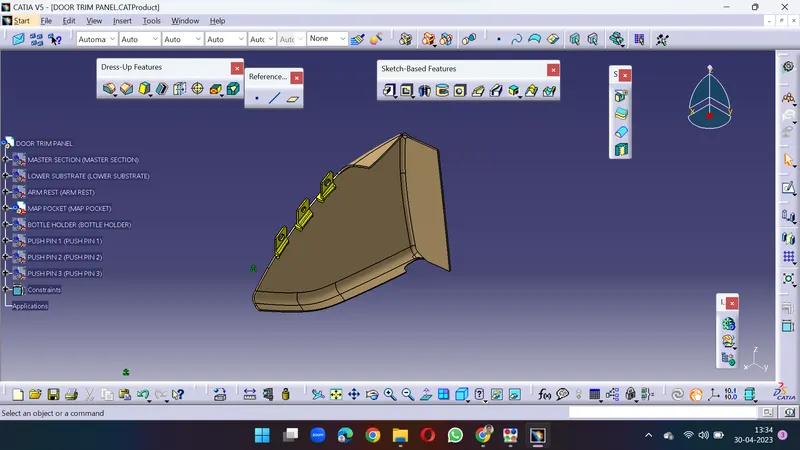
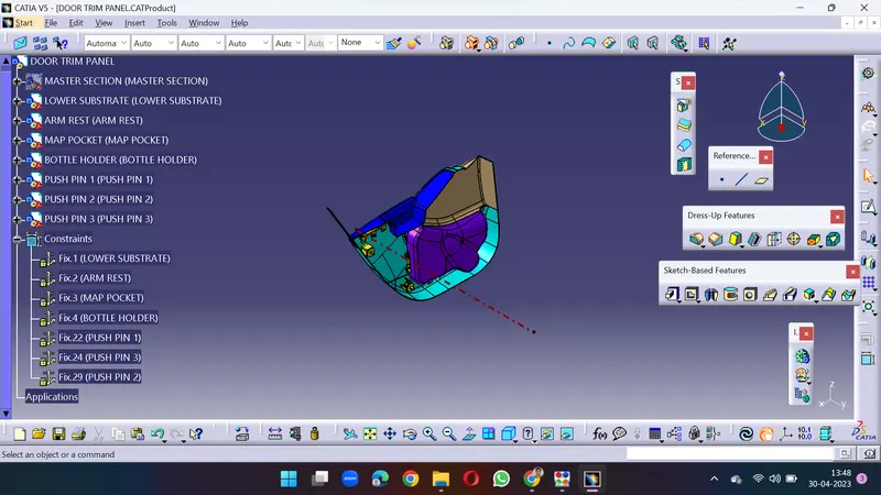
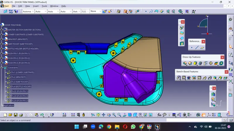
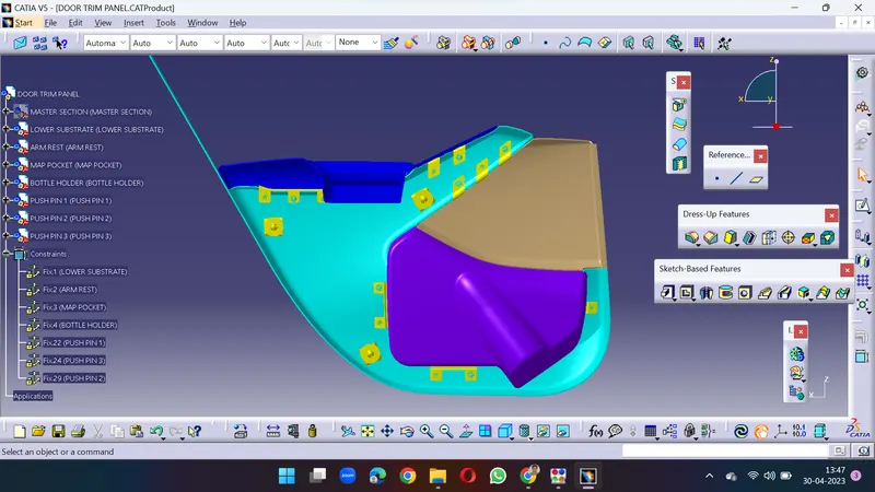
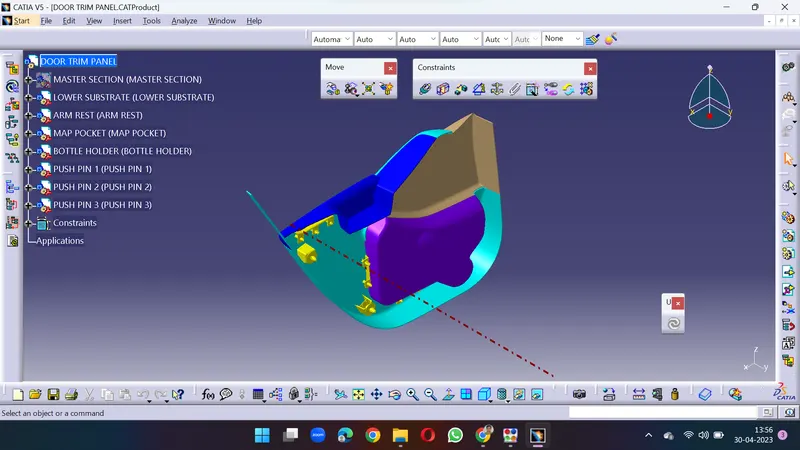
To assemble the parts we need to use the fix option to make it fixed. Also, we need to assemble the pushpins on the top of the dog house.
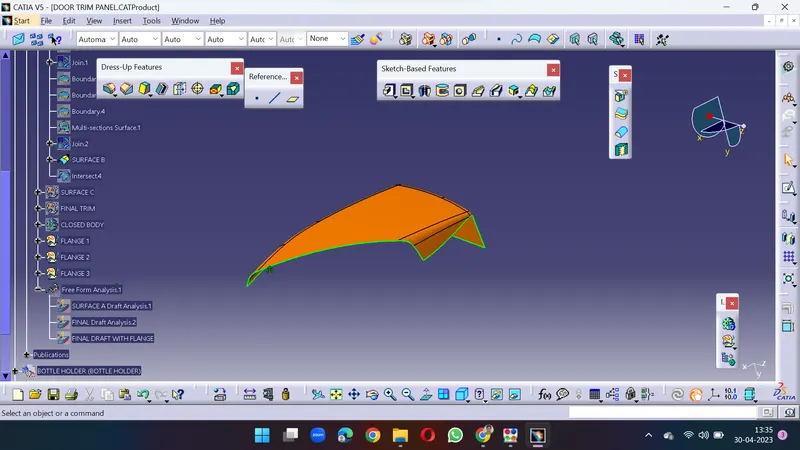
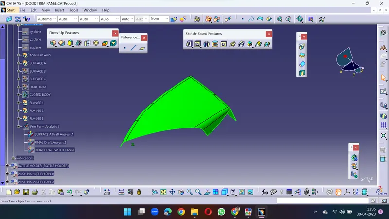
I HAVE ATTACHED THE FILE AND RESPECTIVE IMAGES FOR YOUR REFERENCE.
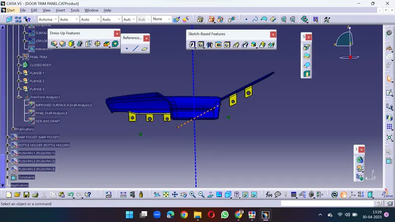
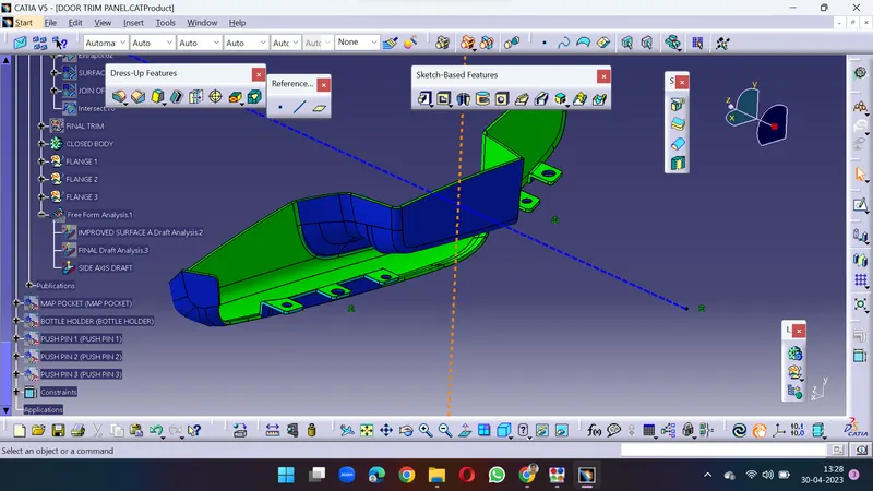
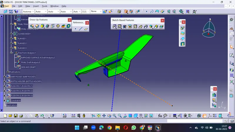
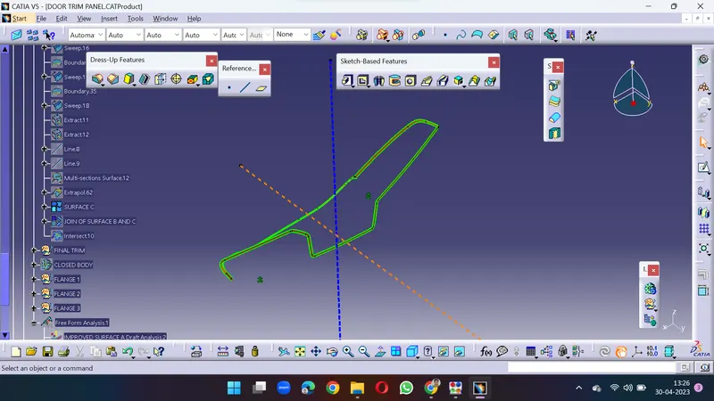
ARMREST IMAGES:
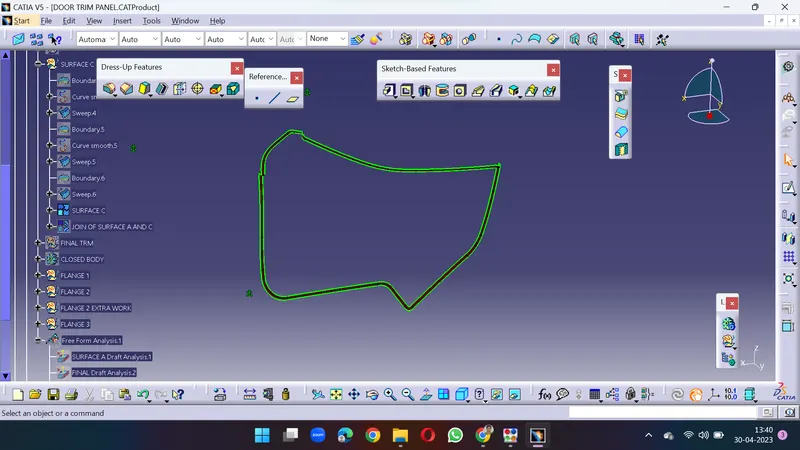
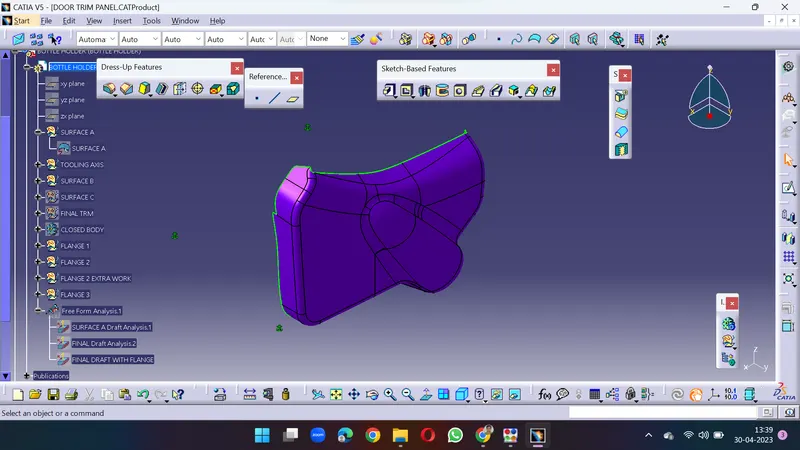
BOTTLE HOLDER:
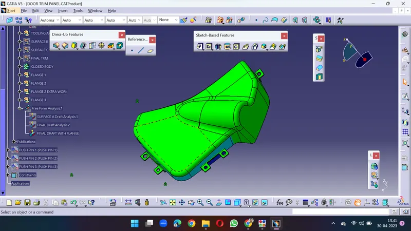
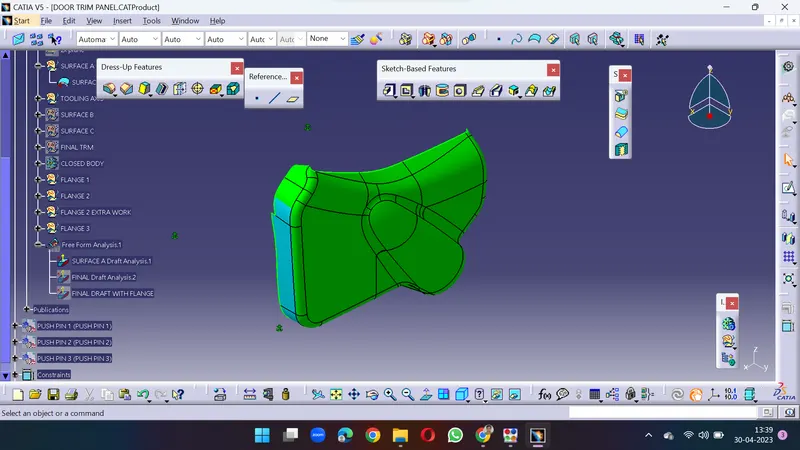
LOWER SUBSTRATE:

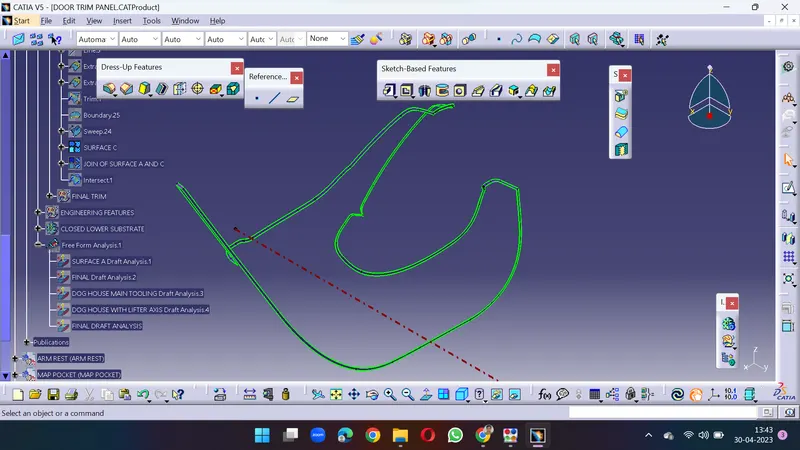
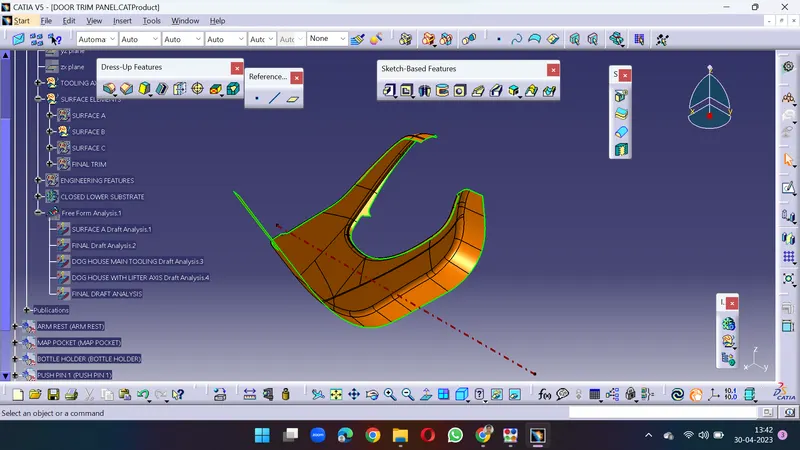
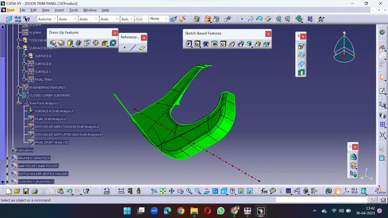
MAP POCKET:
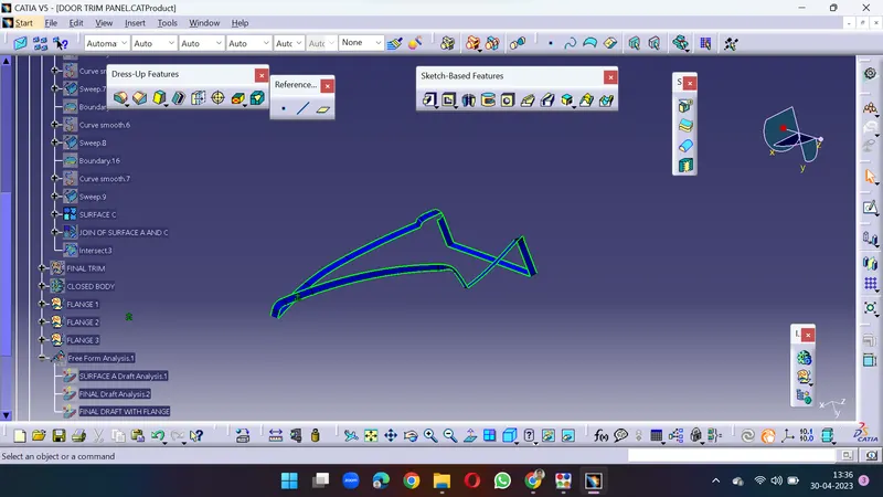
FINAL IMAGES WITH NO SHADING OF MATERIAL:
WITH SHADING MATERIAL:
THANK YOU