Week 12- Final project
DEVELOPMENT OF A DOOR TRIM PANEL
AIM
To create of a cad model considering class A surface norminal thickness and attachment strategy create thickened and attachment strategy.
objective
to create of cad model considering class A surface, Nomianal thickeness and attachment strategy. create thickened part using master section for reference .Create the mouting featuring as per design guidelines in the industry and with master section.
Apply material details.
draft analysis &tooling analysis
introduction
- concept sketch
- styling class A
- feasibility check
- concept vaildation
- new product design
- product development
- proto build
- design vaildation
- pilot production
- mass production
new product development cad
this is the stage where the major work of product design using design software such as nx catiya solidwork solid edge etc in this stage through design all the surface are divided into sub parts from the class a surface and ensuring product should be workble making the 2D drawing for development here product design is going to complete 100%
example designing the car surface with the help of class A and clay model here of class A and clay model here designer goining to detail producing the model from the point of manufacturing assembly etc
procedure :
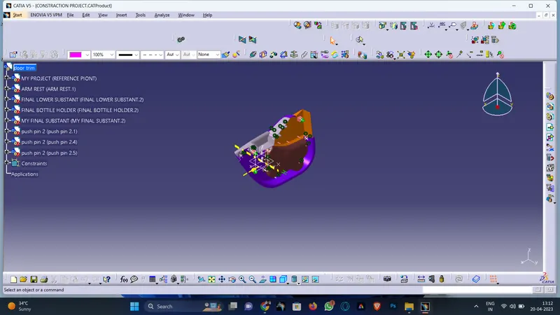
import the file : open> browse file and select the giving filie
class a surface modification as per master section: from the givien data we have to do cad model for lower substrate arm rest and map pocket
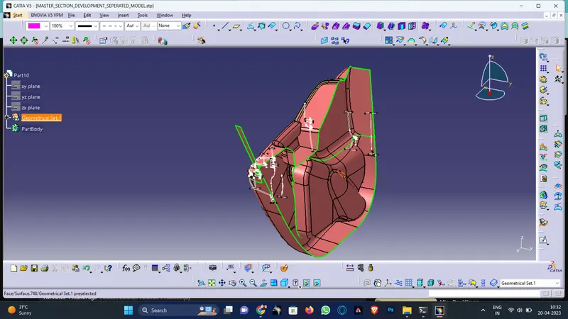
A lower substrate: give lower substare class a along with master surface. find the tooling axies for surface by performing draft analyisis using draft analysis tool(instert analyisis draft analiysis ) so we need to add the master section
B map pocket : given lower substrate class A along with master surface Map pocket is divided into two parts. find the tooling axies for surface by performing drfat analyisis using draft analysis tool (insert >analyisis draft analyis) for two parts. So we need to add surface to class A by using the master section
C arm rest:given lower substrate calss A along with master surface Map pocket is divided into two parts Find the tooling axies for surface by performing draft analyisis using draft analysis tool (inster > analyisi >draft analysis)for two parts So we need to add surface to A by using the master section
Class B surface : for all parts class b surface is create by direct off set and extrapolated
Class c surface :Class C surface are created based on the tooling direction as well surface reference tool used
Created swept surface : the swap tool is is provided to created surface by sweeping a profile along a guide curve in the wireframe and surface by sweeping a profile along a guide curave in the wireframe and surface design workbench of catiya V5.To create a swept surface you first need to draw a profile and a guide curve as two separate sketches
creating swept surface with draft direction :similar to the creating swept surface but we have to select direction for draft.
create lofted mulitisection surface: this tool allows yow to create lofted mutisection surface the surface is created between the section along the computed or user defined spine To created a multi section surface you first need to create section and guide curve next choose the multi section surface button from the surface toolbar the multi section surface definition dialog box is displayed
Final trimming :trimming class A with class C and class A+C with class B. using trimming surface insert > operation > trim
the trim tool allows you to trim two intercting surfaces or curves with repected to each other when you invoke this tool, the trim defination dialong box will be displayed, choose a surface as the first element and the other surface as the second element one side of each surface will be displayed as transparent you can choose the other side button to reverse the side of surface to be trimmed
closed body
the final plastic component is created from the closed body and make the components as solid which is suitable for manufacturing make sure the surface is completly closed before using the close surface operation.only the close body is suitable for manufacturing. and convert all closed surface to soild by using part workbench.
heat stakes
create attachment heat stakes for part to attachment as per master section here some of the heate stake are having ribs becuse they have more then 1.6 of dia so in order to giving strength we have ribs all heat stake are done on lower substrate
hole are made on other parts ie arm rest and map pocket.
Create doghose and push panel with biw part
Draft analyisis & tooling analysis
in the injection molding process plastic product are difficuit to demold due to friction force between the cavity and product might be deformed or damage therfore designer should add a drft angle to the geometric surface of products which is parallel to the unloding direction in order to help the product eject smoothly from the carvity this study uses cad software as the main architecture to develop the function of automatic draft angle recognition and construction. the study is divided into three stage. first,the geometric featuring of product are identified in the cad model by induced algorothm, then the quilts to be added draft design are detemined and classified finally draft are created in different ways according to different surface
the draft analysis button withon catiya v5 will help you quickly gather the draft angle on multiple surface without the need for tedious manul measurements here is a quick run down of how the icon work when you have a given die direction
lower substract :for all heat stake and dog house the draft is given 0.5 deg.
B.map pocket :from the above we have the angle of the sidewall is around 1 degree
c.arm rest :the 2nd part of arm rest draft analysis is failing in global Y direction in order to pass draft we have taken inclined at an angle so that the class A is clearing for draft but attachment featuring are having side core axies.
result
we will get a new product