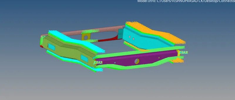
AIM: To mesh the given model and to provide required connectors to the model.

PROCEDURE:

1.Imported the model in IGES format to hyperwork.
2.Mid surface was checked for any missing or topology errors.
3.Mid surfaces was in different collectors,each collector with mid suface is geometrical
  clear to avoid min length errors by automatic cleanup tool.
4.Meshing is done on the mid sufaces from 2D option by auto mesh(mixed).
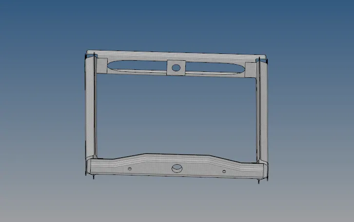
5.All the failed elements are corrected by using cleanup tools in quality index.
6.

  1. First connection is provided at Right rail and front truss by using seam quad(angled +capped +L)

      From 1D option connector is selected ,under this seam is selected.

 In seam panel, weld type is selected as seam quad(angled +capped +L),Weld angle(60) cap angle(70), runoff angle(10) and spacing(5) is provided. Nodes are selected on the right rail surface and components are selected . weld is produced by clicking on create tab.
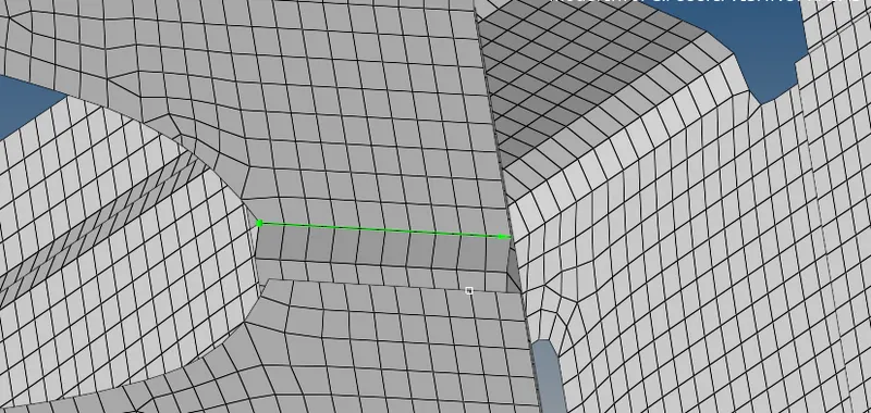
2.second connection is done on Left rail and front truss by using seam quad element.

From 1D option connector is selected ,under this seam is selected.

 In seam panel, weld type is selected as  quad element.Tolerance(5) and spacing(5) is provided. Nodes are selected on the left rail surface and components are selected . weld is produced by clicking on create tab.
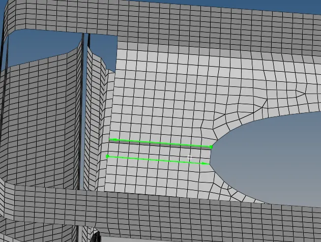
3. Third connection is done on the front truss 2, front truss 1 and right rail 1 by using spot weld with 2 layers and 5mm dia.

 From 1D option connector is selected ,under this spot is selected.

 In spot panel, type is selected as weld.spacing(5),tolerance ,number of layers(2) and diameter(5)  is provided. Nodes are selected on the  surface and components are selected . weld is produced by clicking on create tab.
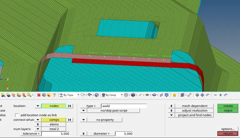
4.Fourth connection is done on the front truss 2, front truss 1 and left rail 1 by using
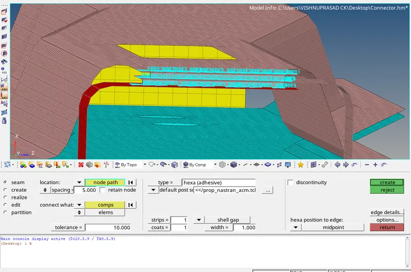
  Hexa adhesive.

  From 1D option connector is selected ,under this seam is selected.

 In seam panel, weld type is selected as Hexa Adhesive.Tolerance(5),spacing(5), coat,
 strip and width values  are provided. Nodes are selected on the  surface and components
 are selected . weld is produced by clicking on create tab.

 Since the connections contain three suface, the connection process is repeated once more
 by selecting node on the lower suface.
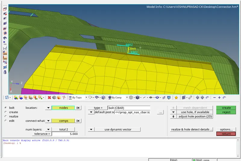
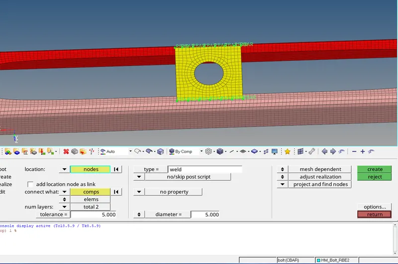
5. Fifth connection is done on Rear truss and right rail by using bolt connector.

   From 1D , connector is selected , under connector bolt is selected. In bolt
   panel,Bolt(CBAR) is selected as the type of bolt. Number of layers (2), tolerance is
   provided .Node is selected on surface and the components are selected to create bolt
   connection by clicking on create option .
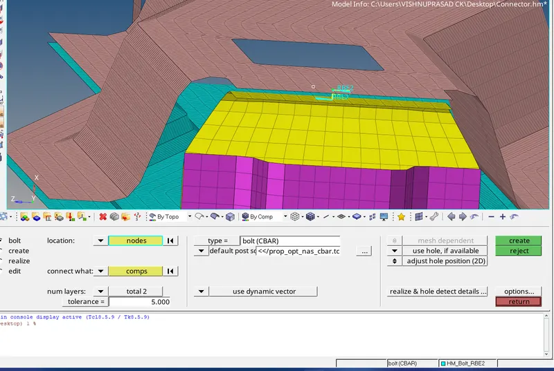
6. Sixth connection is provided on right truss and left rail by using bolt connection.

   From 1D , connector is selected , under connector bolt is selected. In bolt
   panel,Bolt(CBAR) is selected as the type of bolt. Number of layers (2), tolerance is
   provided .Node is selected on a surface and the components are selected to create bolt
   connection by clicking on create option .
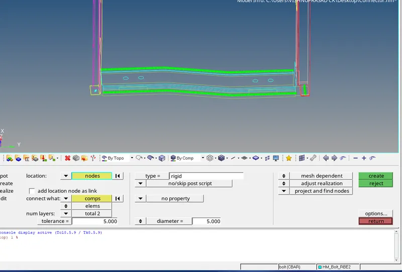
7.Seventh connection is provided on right rail 1 and right rail 2 using spot weld with rigid elements.

    From 1D option connector is selected ,under this spot is selected.

 In spot panel, type is selected as Rigid.spacing(5),tolerance ,number of layers(2) and diameter(5)  is provided. Nodes are selected on the  surface and components are selected . weld is produced by clicking on create tab.
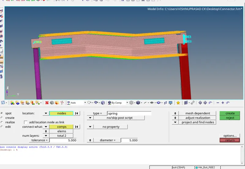
8.Eigth connection is done on left rail 1 and left rail 2 using spot weld with spring
  element.

 From 1D option connector is selected ,under this spot is selected.

 In spot panel, type is selected as Spring .spacing(5),tolerance ,number of layers(2) and
 diameter(5)  is provided. Nodes are selected on the  surface and components are selected
 weld is produced by clicking on create tab.
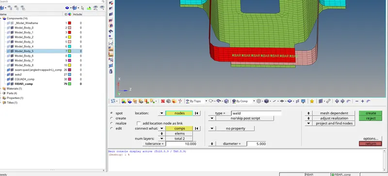
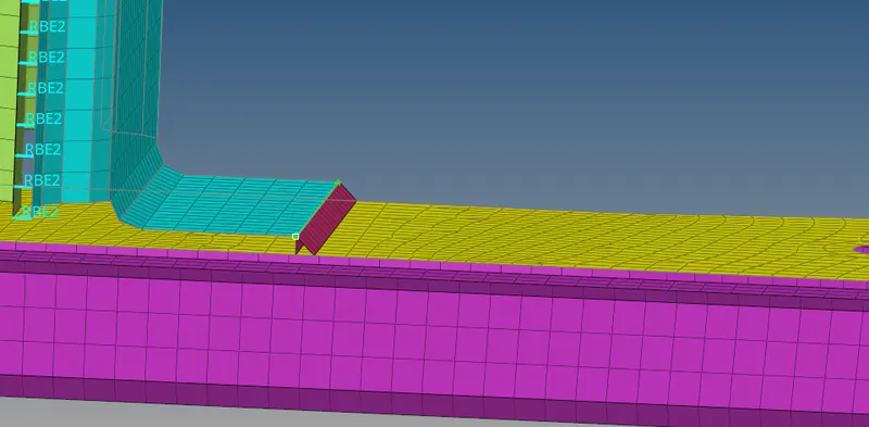
9. Extra coonections are provided where ever required with different connector options
RESULT:

        Meshing is done on the given mid surface and all the possible connections are
        provided by different connector options.