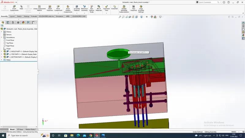
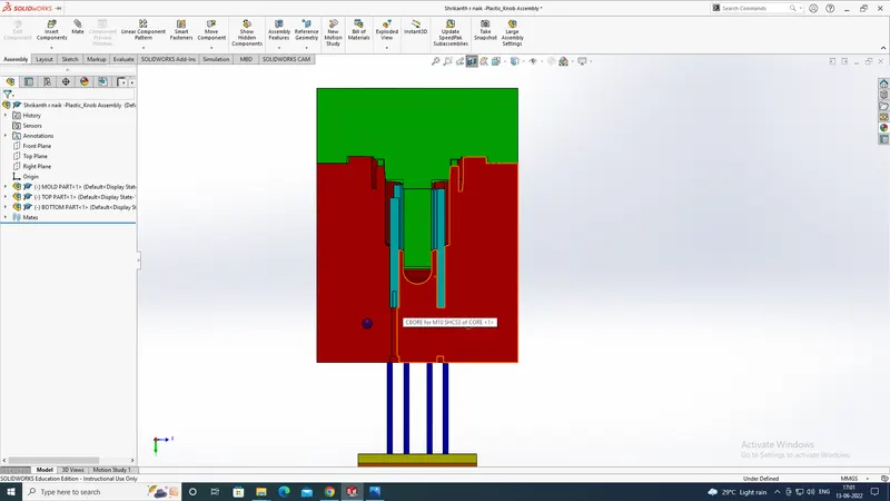
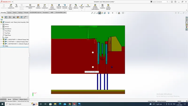
Week 12 Challenge
To create the Mold Design of the product,
first, we will be doing the draft analysis?
The Draft Analysis command enables you to detect if the part you drafted will be easily removed. This type of analysis is performed based on color ranges.
and then with the help of that, we will be deciding the tooling direction, in which we will be getting to know the how the mold will be removed,
and to start creating the mold design of a product
first step
we have to decide the tooling direction
2nd step
is to create the parting line and after creating the parting line and after creating the parting line, if the product has the holes then you have to close the holes before creating the core and cavity to do this we will be using a command shut off surfaces to close the holes.
3rd step
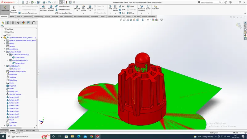
and next is the material we are considering to make the component we should consider that, because they may have shrinkage value so that after the mold has been created and then the component will be undergone shrinkage and will not be getting the component as per the dimensions required, and to get a clear idea about this in this model we have taken the ABS material and its shrinkage value is 0.6 so we will be calculating the shrinkage value by 0.6/100 +1 = 1.006 so we will be getting the shrinkage value and then we will use the scale command to increase the size of the component accordingly to the material and next is to create a parting surface and trim it with the parting line...
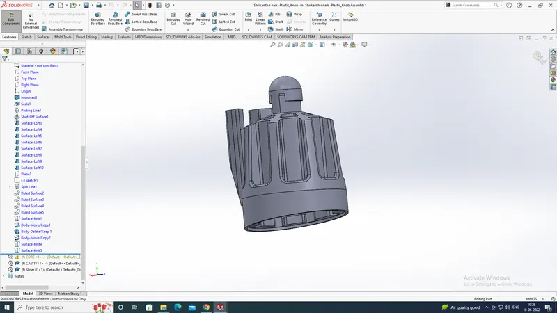
4th step
is to merge the parting surface with the different surfaces to the core and cavity. and in this model, we have to create the split lines to create a parting surface with a ruled surface after that we will be using a lofted surface to fill the gap, and then we will be knitting all the surfaces
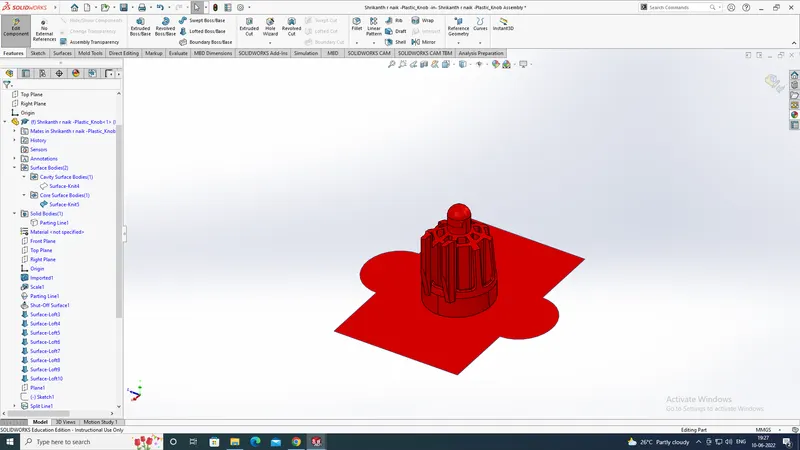
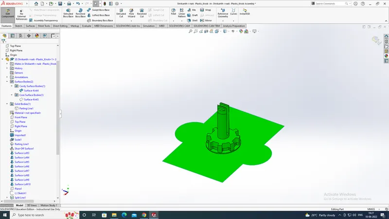
5th step
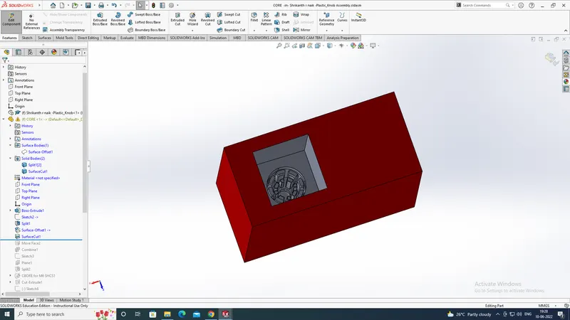
is to create a cuboid to the core and cavity to make this first we will create a box and then we will be trimming it with the merged core and cavity surfaces and then our mold design will be done. and in this model, we will create a cuboid for a 3d profile and a 2d profile.
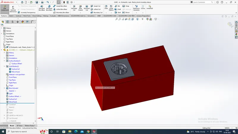
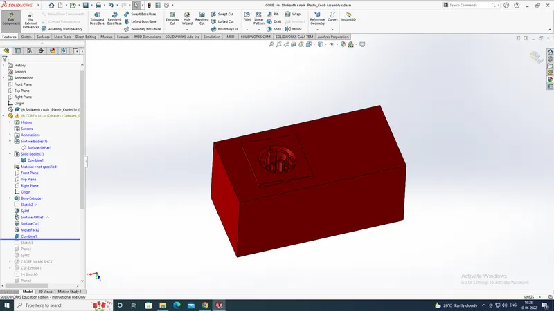
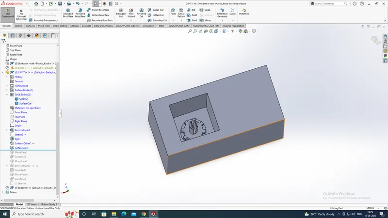
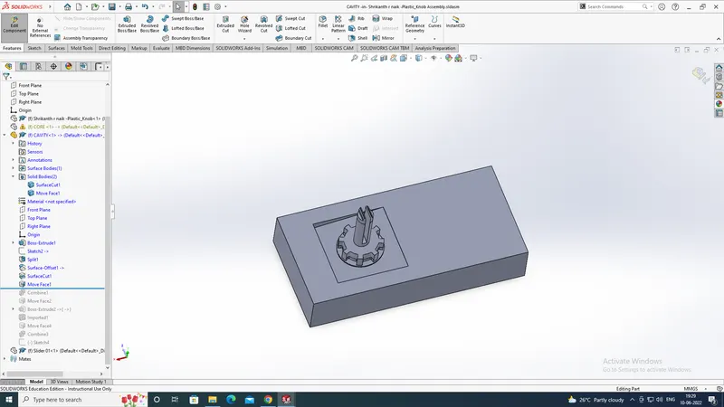
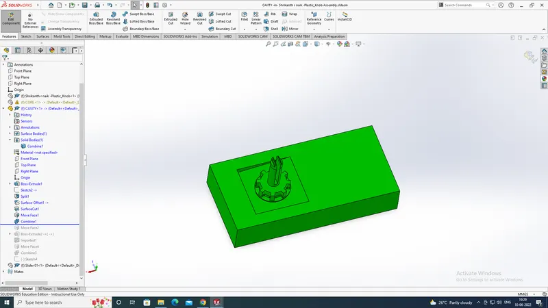
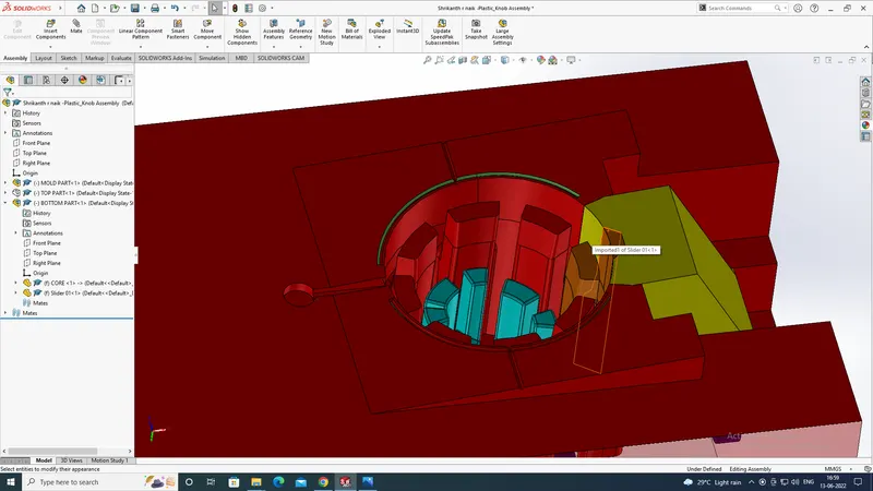
And next, we have to create sliders for the undercut present in the model, and also we have to create the insert because some deep cuts are not possible to get machined...
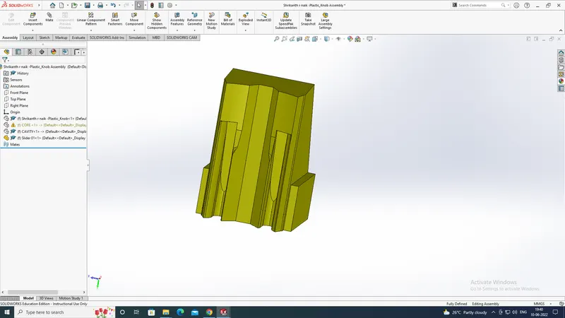
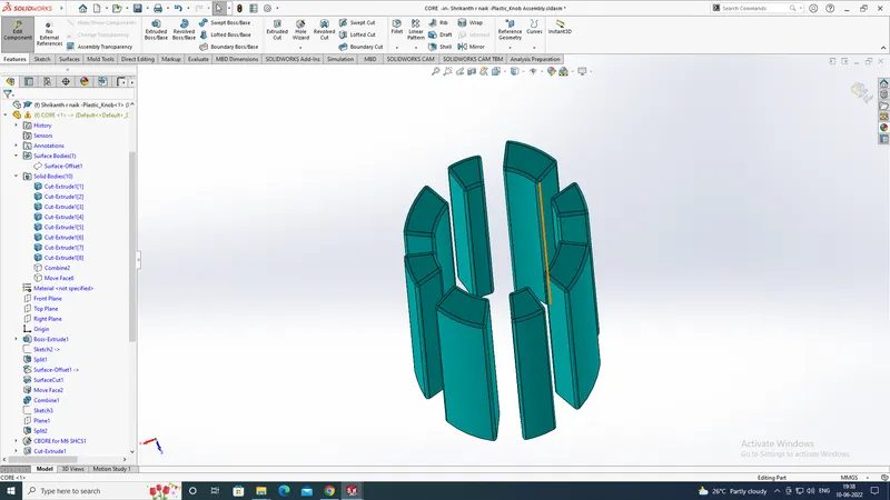
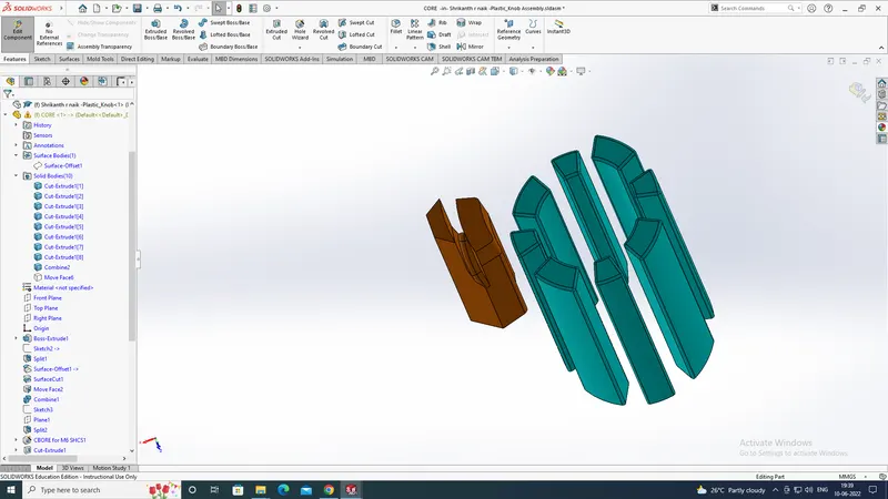
and also we will be making tap holes to the core and will be providing relief to the core and also we will be making a hole in the insert...
and with the help of the combined tool, we will be subtracting it in the cavity model and also we will be providing some relief space to the slider in the core for the movement of the slider...
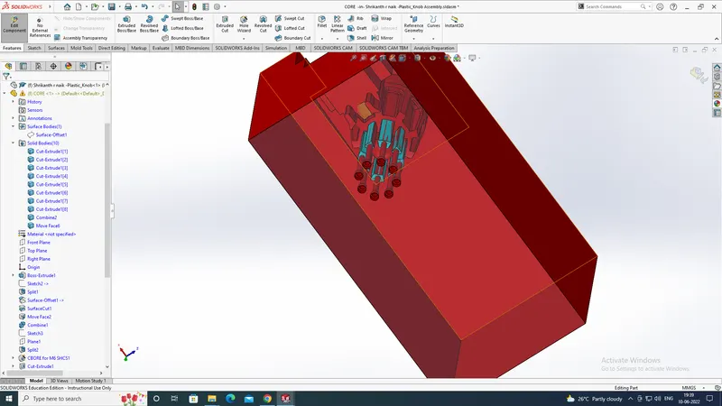
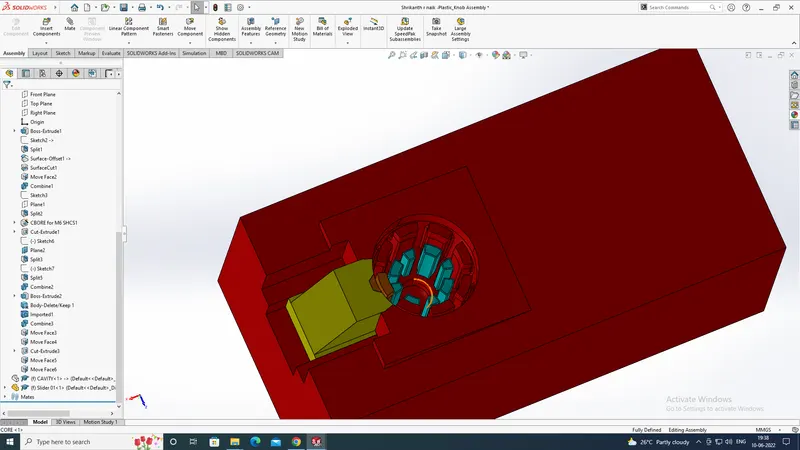
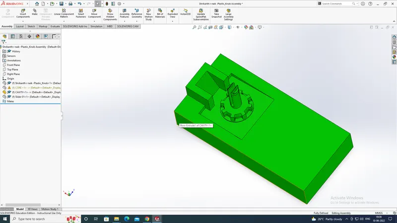
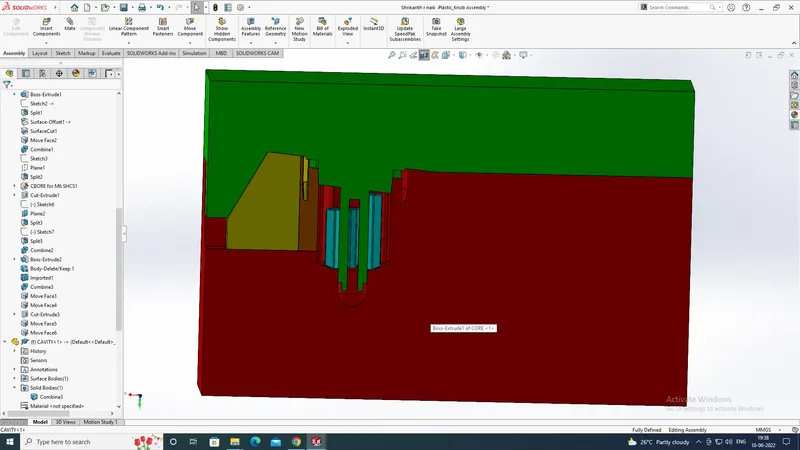
After creating the slider now we will be creating the sprue and runner and a gating system for the model..And then we will be creating the ejector pins for the model as per the required dimensions,
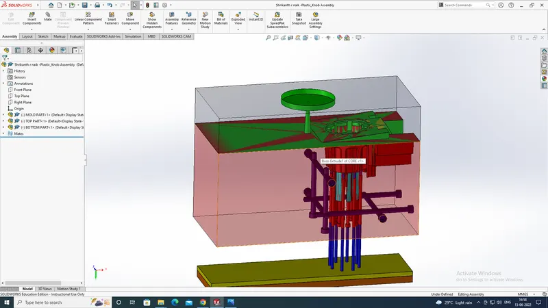
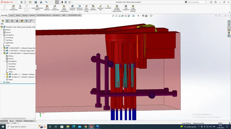
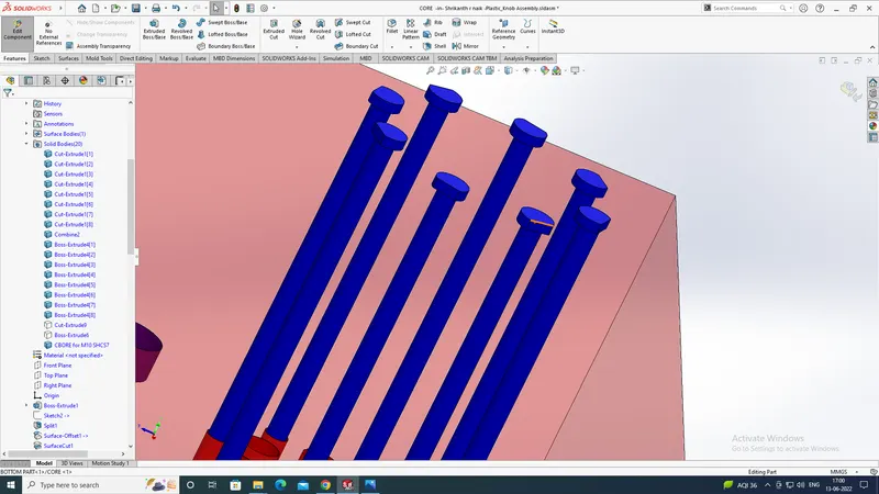
and now we will be creating the ejector pin back support
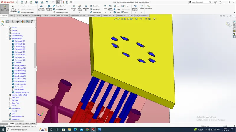
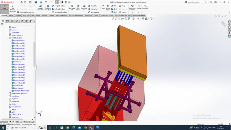
and after that now we will be creating the air vents, that help to release the trapped air present in the model...
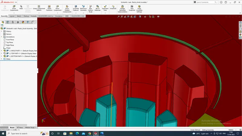
and then we will be creating the cooling channels for the model that helps to avoid wrappage problem in the model...