Week 11 - Simulation of Flow through a pipe in OpenFoam
Simulation of Axi-symmetric model of constant cross section pipe of laminar flow type
Outputs expected from this project are,
1) Get the required geometry from editing blockMeshDict file and giving P,U boundary conditions
2) Developing flow through pipe formluae
3) Automation of generation of blockMeshDict file in Matlab
4) Post process the results
5) Comaring the results of numerical simulation with the analytical values calculated
1) Get the required geometry from editing blockMeshDict file and giving P,U boundary conditions
We have to go to tut folder in terminal , then going to icoFoam folder, copying the cavity folder from that into RUN folder. Then in system we get the BlockMeshDict file and then it can be edited.
For creating wedge type geometry, we have assumed the following parameters ,
a) θ = 2 degrees
b) length of pipe = 1.5 m
c) Radius of pipe = 0.005 m
d) Working fluid is WATER
Below is the blocmeshDict file of the required geometry ,
/*--------------------------------*- C++ -*----------------------------------*\
  =========                 |
  \\      /  F ield         | OpenFOAM: The Open Source CFD Toolbox
   \\    /   O peration     | Website:  https://openfoam.org
    \\  /    A nd           | Version:  8
     \\/     M anipulation  |
\*---------------------------------------------------------------------------*/
FoamFile
{
    version     2.0;
    format      ascii;
    class       dictionary;
    object      blockMeshDict;
}
// * * * * * * * * * * * * * * * * * * * * * * * * * * * * * * * * * * * * * //

convertToMeters 1;

vertices
(
    (0 0 0)
    (0 0.00499 -0.0000872) // x dir
    (0 0.00499 0.0000872) // y dir
    (1.5 0 0) //z
    (1.5 0.00499 -0.0000872)
    (1.5 0.00499 0.0000872)

);

blocks
(
    hex (0 1 2 0 3 4 5 3) (20 1 200) simpleGrading (1 0.2 1)

);

edges
(
/*
arc 1 2 (0 0.01 0)
arc 3 4 (3 0.01 0)
*/
);

boundary
(

    inlet
    {
        type patch;
        faces
        (
            (0 2 1 0)

        );
    }
    outlet
    {
        type patch;
        faces
        (

            (3 4 5 3)
        );
    }

    noslipwalls
    {
        type wall;
        faces
        (

            (1 2 5 4)
        );
    }

    front
    {
        type wedge;
        faces
        (

            (0 3 5 2)
        );
    }

    back
    {
        type wedge;
        faces
        (

            (0 1 4 3 )
        );
    }

        axis
    {
        type empty;
        faces
        (

            (0 3 3 0)
        );
    }

);

mergePatchPairs
(
);

// ************************************************************************* //
Vertices
vertices are calculated in below manner,
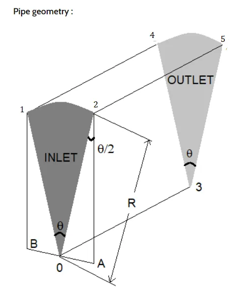
0(0 0 0)
1(0 0.00499 -0.0000872) //(0 (D/2)*sin(θ/2) -(D/2)*cos(θ/2) )
2(0 0.00499 0.0000872) //(0 (D/2)*sin(θ/2) (D/2)*cos(θ/2) )
3(1.5 0 0) // (L 0 0 )
4(1.5 0.00499 -0.0000872) //(L (D/2)*sin(θ/2) -(D/2)*cos(θ/2) )
5(1.5 0.00499 0.0000872) //(L (D/2)*sin(θ/2) (D/2)*cos(θ/2) )
edges
Arcs will be included in the edges as below
arc 1 2 (Coordinated of centre point in between 1 and 2)
arc 4 5 (Coordinated of centre point in between 4 and 5)
Pressure setting as outlet pressure boundary condition:
/*--------------------------------*- C++ -*----------------------------------*\
  =========                 |
  \\      /  F ield         | OpenFOAM: The Open Source CFD Toolbox
   \\    /   O peration     | Website:  https://openfoam.org
    \\  /    A nd           | Version:  8
     \\/     M anipulation  |
\*---------------------------------------------------------------------------*/
FoamFile
{
    version     2.0;
    format      ascii;
    class       volScalarField;
    object      p;
}
// * * * * * * * * * * * * * * * * * * * * * * * * * * * * * * * * * * * * * //

dimensions      [0 2 -2 0 0 0 0];

internalField   uniform 0;

boundaryField
{
    inlet
    {
        type            zeroGradient;
    }

    outlet
    {
        type            fixedValue;
        Value		 uniform 0;
    }

    front
    {
        type            wedge;
    }

    back
    {
        type            wedge;
    }

    axis
    {
    	type		empty;
    }

    noslipwalls
    {
    	type		zeroGradient;
    }
}

// ************************************************************************* //
Velocity setting as inlet velocity boundary condition:
/*--------------------------------*- C++ -*----------------------------------*\
  =========                 |
  \\      /  F ield         | OpenFOAM: The Open Source CFD Toolbox
   \\    /   O peration     | Website:  https://openfoam.org
    \\  /    A nd           | Version:  8
     \\/     M anipulation  |
\*---------------------------------------------------------------------------*/
FoamFile
{
    version     2.0;
    format      ascii;
    class       volVectorField;
    object      U;
}
// * * * * * * * * * * * * * * * * * * * * * * * * * * * * * * * * * * * * * //

dimensions      [0 1 -1 0 0 0 0];

internalField   uniform (0 0 0);

boundaryField
{
    inlet
    {
        type            fixedValue;
        value           uniform (0.1869 0 0);
    }

    outlet
    {
        type            zeroGradient;
    }

    noslipwalls
    {
        type            noSlip;
    }

    axis
    {
    	type		empty;
    }

    front
    {
    	type 		wedge;
    }

    back
    {
    	type 		wedge;
    }
}

// ************************************************************************* //
Trasport Properties folder
/*--------------------------------*- C++ -*----------------------------------*\
  =========                 |
  \\      /  F ield         | OpenFOAM: The Open Source CFD Toolbox
   \\    /   O peration     | Website:  https://openfoam.org
    \\  /    A nd           | Version:  8
     \\/     M anipulation  |
\*---------------------------------------------------------------------------*/
FoamFile
{
    version     2.0;
    format      ascii;
    class       dictionary;
    location    "constant";
    object      transportProperties;
}
// * * * * * * * * * * * * * * * * * * * * * * * * * * * * * * * * * * * * * //

nu              [0 2 -1 0 0 0 0] 8.9e-7;


// ************************************************************************* //
ControlDict file
/*--------------------------------*- C++ -*----------------------------------*\
  =========                 |
  \\      /  F ield         | OpenFOAM: The Open Source CFD Toolbox
   \\    /   O peration     | Website:  https://openfoam.org
    \\  /    A nd           | Version:  8
     \\/     M anipulation  |
\*---------------------------------------------------------------------------*/
FoamFile
{
    version     2.0;
    format      ascii;
    class       dictionary;
    location    "system";
    object      controlDict;
}
// * * * * * * * * * * * * * * * * * * * * * * * * * * * * * * * * * * * * * //

application     icoFoam;

startFrom       startTime;

startTime       0;

stopAt          endTime;

endTime         58;

deltaT          0.01;

writeControl    timeStep;

writeInterval   20;

purgeWrite      0;

writeFormat     ascii;

writePrecision  6;

writeCompression off;

timeFormat      general;

timePrecision   6;

runTimeModifiable true;


// ************************************************************************* //
Solver used is icoFoam which uses PISO algorithm to solve continuity and momentum equations.
2) Developing flow through pipe formluae
Flow in a conduit can be either develpoing or fully developed flow. Considering a laminar flow entering the pipe, the velocity profile changes as it moves inside pipe. This region of changing velocity profile is called as developing flow. After the parabolic profile is acheived, the flow profile does not change in streamwise direction and this flow is called as fully developed flow. The distance required for a flow to become developed is called as entrance length and it depends upon shear stresses that act on the wall.
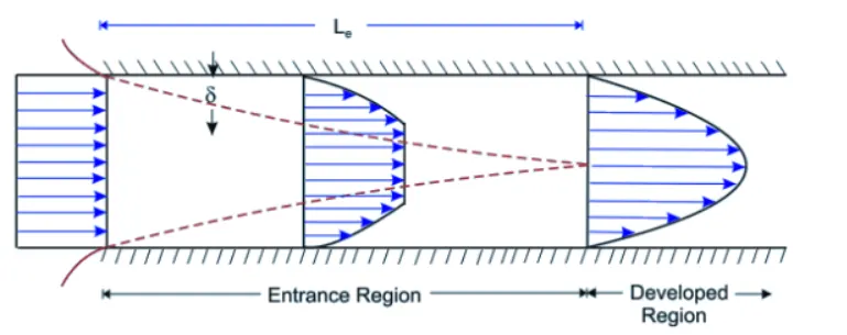
This fully developed flow is termed as Hagen- Poiseuille's flow and forlulae related to this flow are as below,
1) Pressure loss during the fluid flow
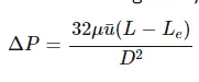
where`△` is pressure difference
μ is viscosity of fluid
u is average velocity of fluid
L is length of pipe
Le is entrance length of pipe
D is diameter of pipe
2) Reynold's number
For pipe flow applications , it is very important to know whether the flow is laminayr or turbulent. Equations and method that are applied to these flows to analyse the flow are different.
Typical criterion to decide whether pipe flow is laminar or turbulent is value of Reynold's number.
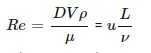
where D is pipe diameter
V is average flow velocity in pipe
ρ is density of flowing fluid
μ is dynamic viscosity of fluid
ν is kinematic viscosity of fluid
Re is dimensionless number
When Re < 2300, it is Laminar flow
Re > 4000, it is Turbulent
3) Entry length Le = 0.06*Re*D
4) Length of pipe = L = 0.5 + Le
5) Average flow velocity = Vavg = Re.μ/(density* D)
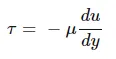
6) Shear stress:
3) Automation of generation of blockMeshDict file in Matlab
clear all
close all
clc

% File parsing

% inputs
Re = 2100;
rho = 1000;
mu = 8.9e-7;
v = 0.1869 % m/s
prompt = 'What is pipe diameter' ;
D = input(prompt);

% Total pipe length

L = 1.5; %m

% Le = 0.06*Re*D ;
% L = Le + 0.5;
% angle of wedge

prompt = 'What is wedge angle ?' ;
theta = input(prompt) ;

if theta> 5
    theta = fprintf('Choose the angle lesse than 5 degrees')
end

a = (D/2)*cosd(theta/2);
b = (D/2)*sind(theta/2);

v0 = [0 ,0 ,0];
v1= [0 ,a, -b];
v2= [0, a, b];
v3= [L, 0, 0];
v4= [L, a, -b];
v5= [L, a, b];


f1 = fopen('blockmeshdict.txt', 'w') ;

fprintf(f1,'%s \n', '/*--------------------------------*- C++ -*----------------------------------*\');
fprintf(f1, '%s \n','  =========                 |');
fprintf(f1,'%s \n', '  \\      /  F ield         | OpenFOAM: The Open Source CFD Toolbox');
fprintf(f1, '%s \n', '   \\    /   O peration     | Website:  https://openfoam.org');
fprintf(f1, '%s \n', '    \\  /    A nd           | Version:  8');
fprintf(f1, '%s \n', '     \\/     M anipulation  |');
fprintf(f1, '%s \n', '\*---------------------------------------------------------------------------*/');
fprintf(f1, '%s \n', 'FoamFile');
fprintf(f1, '%s \n', '{');
fprintf(f1, '%s \n', '    version     2.0;');
fprintf(f1, '%s \n', '    format      ascii;');
fprintf(f1, '%s \n', '    class       dictionary;');
fprintf(f1, '%s \n', '    object      blockMeshDict;');
fprintf(f1, '%s \n', '}');
fprintf(f1, '%s \n', '// * * * * * * * * * * * * * * * * * * * * * * * * * * * * * * * * * * * * * //');

% For a space for one line
fprintf(f1, '\n');

fprintf(f1, '%s \n','convertToMeters 1;')

% For a space for one line
fprintf(f1, '\n');

fprintf(f1, '%s \n','vertices');
fprintf(f1, '%s \n','(');

fprintf(f1, '(%f %f %f)\n',v0(1), v0(2),v0(3));
fprintf(f1, '(%f %f %f)\n',v1(1), v1(2),v1(3));
fprintf(f1, '(%f %f %f)\n',v2(1), v2(2),v2(3));
fprintf(f1, '(%f %f %f)\n',v3(1), v3(2),v3(3));
fprintf(f1, '(%f %f %f)\n',v4(1), v4(2),v4(3));
fprintf(f1, '(%f %f %f)\n',v5(1), v5(2),v5(3));

fprintf(f1, '%s \n',');');

fprintf(f1, '\n');

fprintf(f1, '%s \n','blocks');
fprintf(f1, '%s \n','(');
fprintf(f1, '%s \n','    hex (0 1 2 0 3 4 5 3) (20 1 200) simpleGrading (1 0.2 1)');
fprintf(f1, '\n');
fprintf(f1, '%s \n',');');

fprintf(f1, '%s \n','edges');
fprintf(f1, '%s \n','(');
fprintf(f1, '%s \n',');');

fprintf(f1, '%s \n','boundary');
fprintf(f1, '%s \n','(');
fprintf(f1, '\n');

fprintf(f1, '%s \n','    inlet');
fprintf(f1, '%s \n','    {');
fprintf(f1, '%s \n','        type patch;');
fprintf(f1, '%s \n','        faces');
fprintf(f1, '%s \n','        (');
fprintf(f1, '%s \n','            (0 2 1 0)');
fprintf(f1, '%s \n',');');
fprintf(f1, '%s \n','}');

fprintf(f1, '%s \n','    outlet');
fprintf(f1, '%s \n','    {');
fprintf(f1, '%s \n','        type patch;');
fprintf(f1, '%s \n','        faces');
fprintf(f1, '%s \n','        (');
fprintf(f1, '%s \n','            (3 4 5 3)');
fprintf(f1, '%s \n',');');
fprintf(f1, '%s \n','}');

fprintf(f1, '%s \n','    noslipwalls');
fprintf(f1, '%s \n','    {');
fprintf(f1, '%s \n','        type wall;');
fprintf(f1, '%s \n','        faces');
fprintf(f1, '%s \n','        (');
fprintf(f1, '%s \n','            (1 2 5 4)');
fprintf(f1, '%s \n',');');
fprintf(f1, '%s \n','}');

fprintf(f1, '%s \n','    front');
fprintf(f1, '%s \n','    {');
fprintf(f1, '%s \n','        type wedge;');
fprintf(f1, '%s \n','        faces');
fprintf(f1, '%s \n','        (');
fprintf(f1, '%s \n','            (0 3 5 2)');
fprintf(f1, '%s \n',');');
fprintf(f1, '%s \n','}');

fprintf(f1, '%s \n','    back');
fprintf(f1, '%s \n','    {');
fprintf(f1, '%s \n','        type wedge;');
fprintf(f1, '%s \n','        faces');
fprintf(f1, '%s \n','        (');
fprintf(f1, '%s \n','            (0 1 4 3)');
fprintf(f1, '%s \n',');');
fprintf(f1, '%s \n','}');

fprintf(f1, '%s \n','    axis');
fprintf(f1, '%s \n','    {');
fprintf(f1, '%s \n','        type empty;');
fprintf(f1, '%s \n','        faces');
fprintf(f1, '%s \n','        (');
fprintf(f1, '%s \n','            (0 3 3 0)');
fprintf(f1, '%s \n',');');
fprintf(f1, '%s \n','}');

fprintf(f1, '\n');
fprintf(f1, '%s \n',');');

fprintf(f1, '%s \n','mergePatchPairs');

fprintf(f1, '%s \n','(');
fprintf(f1, '%s \n',');');

fprintf(f1, '\n');
fprintf(f1, '%s \n','// ************************************************************************* //');
Results :
A) Numerical results from OpenFoam
1) Velocity plot at a distance of 1.2m as it will be a developed flow at that distance.
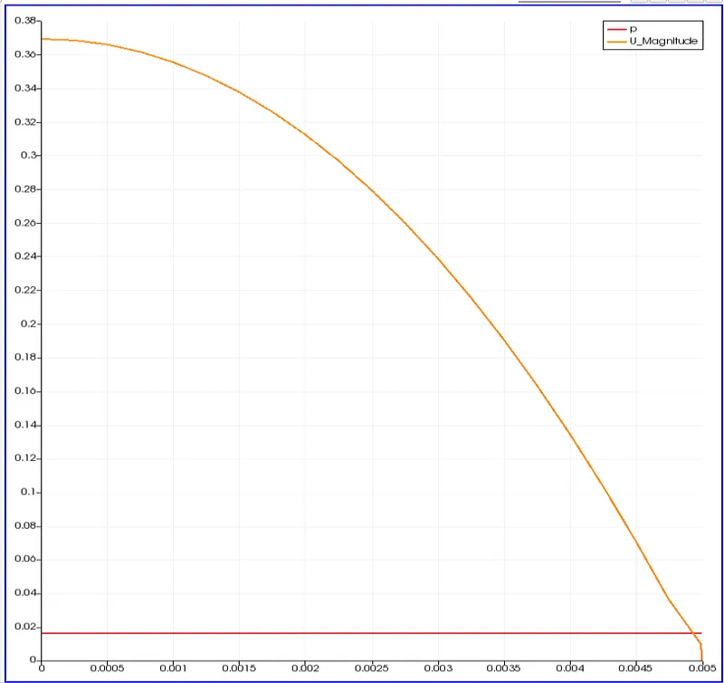
The value of velocity = 0.37 m/s
2) Pressure drop plot all over the length of pipe
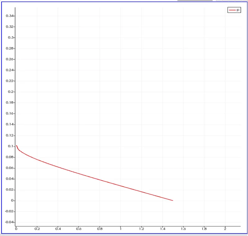
deltaP max = 0.80 KPa
3) Shear stress at a distance of 1.2m from the inlet
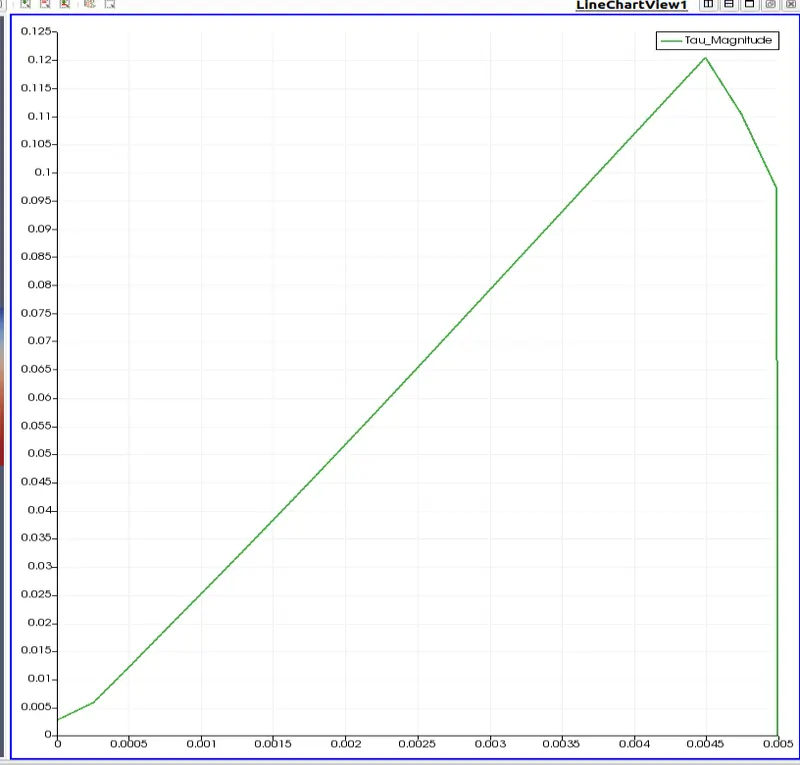
Taumax = 0.12 Pa
A) Analytical results from formulae
1) Vmax = 2* Vavg
Vavg = 0.186 m/s
Vmax = 0.372 m/s
2) Pressure drop = (32*mu*Vavg*(Le-L))/ D^2
△P = 79. 45 Pa
3) Shear stress = -R*△P / (2*L)
Tau = 0.132 Pa
Comparison chart for Numerical vs Analytical results
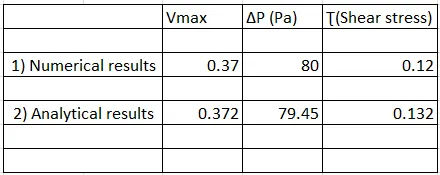
Conclusion: In this way, the comparison of numerical and analytical analysis has been done and it is observed that answers by both methods have small difference in them. Shear stress at the wall is the maximum and it starts decreasing and becomes zero at the centre of the pipe.