Week 11 - Simulation of Flow through a pipe in OpenFoam
AIM: To Simulate the axi-symmetric flow through a pipe by applying the wedge boundary condition on openFoam.
OBJECTIVE:
1. Validate Hydro-dynamic length with the numerical result
2. Validate the fully developed flow velocity profile with its analytical profile
3. Validate maximum velocity and pressured drop for fully developed flow
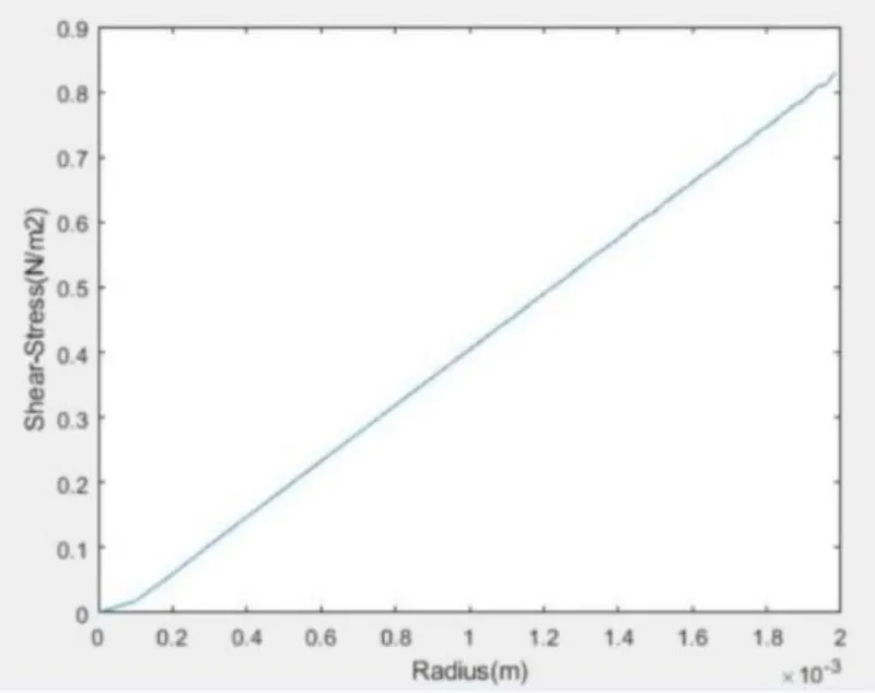
4. Post-process Shear stress and validate wall shear stress for fully developed flow
5. The flow is laminar and flows through a constant cross-section pipe at an inlet Reynold's number of 2100.
THEORY AND EXPLANATION:
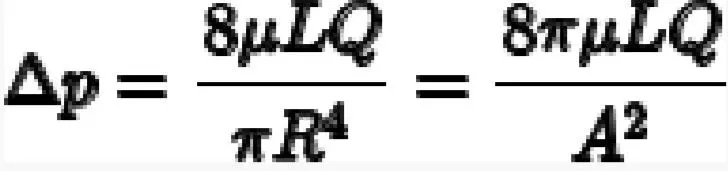
In nonideal fluid dynamics, the Hagen–Poiseuille equation, also known as the Hagen–Poiseuille law, is a physical law that gives the pressure
drop in an incompressible and Newtonian fluid in laminar flow flowing through a long cylindrical pipe of constant cross section.
Eqaution for standard fluid-kinetics is,
where:
Δp is the pressure difference between the two ends,
L is the length of pipe,
μ is the dynamic viscosity,
Q is the volumetric flow rate,
R is the pipe radius,
A is the cross section of pipe
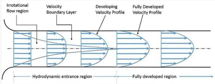
Expected Velocity Profile:
FOLLOWING ASSUMPTIONS:
1. The distance the fluid has to travel to become fully developed is given by the Entry Length formula.
2. Given Reynolds number is 2100. This implies flow is laminar
3. Hence Entry length formula for Laminar is given by: L/d 0.06. Re
4. where L is effective length; d is dia of pipe and Re is reyonolds number.
5. Assuming the dia of pipe as 10mm; substituting the values, we get L = 1.2m
STEPS:
1. First, the geometry is created in the blockmesh Dict file, this is done by creating the file through the matlab code.
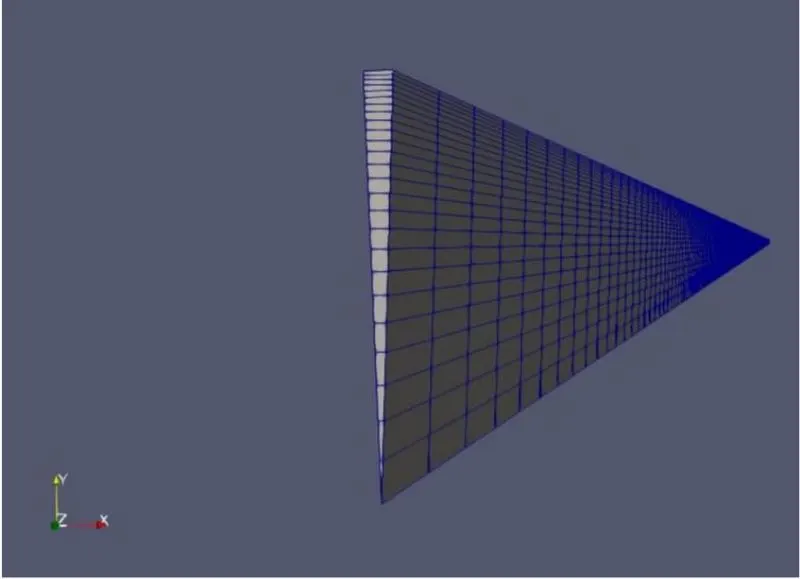
2. The mesh is generated according to requirement.
3. The velocity and preassure bc are applied
4. The controlDict file is edited for Simulation run time and timestep;
5. After the geometry is input, the simulation can be started by calling 'icoFoam' command in the terminal.
6. 'paraFoam' command helps to open paraView
7. The shear stress diagram is obtained by post-processing the velocity results obtained from Openfoam.
MATLAB PROGRAM:
BLOCKMESHDICT FILE:
clc
 clear all
 close all
 % variable values
 D = 0.01;
 r = D/2;
 L = 1.2;
 theta = input(' input the value of wedge angle=');
 % String for header,
 h1 =' /*---------------------------------*- C++ -*-------------------------------------------------* ';
 h2 =' | ========== | |';
 h3 =' | \ / F ield | OpenFOAM: The Open Source CFD Toolbox |';
 h4 =' | \ / O peration | Version: 7 |';
 h5 =' | \ / A nd | Web: www.OpenFOAM.org |';
 h6 =' | \ / M anipulation | |';
 h7 =' *------------------------------------------------------------------------------------------*/ ';
 h8 =' FoamFile';
 h9 ='{';
 h10 =' version 2.0;';
 h11 =' format ascii;';
 h12 =' class dictionary;';
 h13 =' object blockMeshDict;';
 h14 ='}';
 h15 =' // * * * * * * * * * * * * * * * * * * * * * * * * * * * * * * * * * * * * * * * * * * * * * \';
 conv ='convertToMeters 1;';
 sp1 = blanks(5); %sp = space
 sp2 = blanks(10);
 sp3 = blanks(15);
 v_0 = [0 0 0];
 v_1 = [r*sind(theta/2) r*cosd(theta/2) 0];
 v_2 = [-r*sind(theta/2) r*cosd(theta/2) 0];
 v_3 = [0 0 L];
 v_4 = [r*sind(theta/2) r*cosd(theta/2) L];
 v_5 = [-r*sind(theta/2) r*cosd(theta/2) L];
 block ='hex (0 0 1 2 3 3 4 5) (1 50 200) simpleGrading (1 0.5 1)';
 edge1 ='arc 1 2';
 edge2 ='arc 4 5';
 e1 = [0 r 0];
 e2 = [0 r L];
 inlet = '(0 0 2 1)';
 outlet = '(3 4 5 3)';
 wedge1 = '(0 1 4 3)';
 wedge2 = '(3 5 2 0)';
 wall =' (4 1 2 5)';
 axis =' (0 3 3 0)';
 final = '//
*************************************************************************************************************
************************************* //';
 f1 = fopen('blockMeshDict','wt');
 fprintf(f1,'%sn',h1);
 fprintf(f1,'%sn',h2);
 fprintf(f1,'%sn',h3);
 fprintf(f1,'%sn',h4);
 fprintf(f1,'%sn',h5);
 fprintf(f1,'%sn',h6);
 fprintf(f1,'%sn',h7);
 fprintf(f1,'%sn',h8);
 fprintf(f1,'%sn',h9);
 fprintf(f1,'%sn',h10);
 fprintf(f1,'%sn',h11);
 fprintf(f1,'%sn',h12);
 fprintf(f1,'%sn',h13);
 fprintf(f1,'%sn',h14);
 fprintf(f1,'%sn',h15);
 fprintf(f1,'n');
 fprintf(f1,'%sn',conv);
 fprintf(f1,'n');
 fprintf(f1,'%sn','vertices');
 fprintf(f1,'%sn','(');
 fprintf(f1,'%s (%f %f %f) n',sp1,v_0(1),v_0(2),v_0(3));
 fprintf(f1,'%s (%f %f %f) n',sp1,v_1(1),v_1(2),v_1(3));
 fprintf(f1,'%s (%f %f %f) n',sp1,v_2(1),v_2(2),v_2(3));
 fprintf(f1,'%s (%f %f %f) n',sp1,v_3(1),v_3(2),v_3(3));
 fprintf(f1,'%s (%f %f %f) n',sp1,v_4(1),v_4(2),v_4(3));
 fprintf(f1,'%s (%f %f %f) n',sp1,v_5(1),v_5(2),v_5(3));
 fprintf(f1,'%s n',');');
 fprintf(f1,'n');
 fprintf(f1,'%sn','blocks');
 fprintf(f1,'%sn','(');
 fprintf(f1,'%s %s n',sp1,block);
 fprintf(f1,'%s n',');');
 fprintf(f1,'n');
 fprintf(f1,'%s n','edges');
 fprintf(f1,'%s n','(');
 fprintf(f1,'%s %s (%f %f %f) n',sp1,edge1,e1(1),e1(2),e1(3));
 fprintf(f1,'%s %s (%f %f %f) n',sp1,edge2,e2(1),e2(2),e2(3));
 fprintf(f1,'%s n',');');
 fprintf(f1,'n');
 fprintf(f1,'%s n','boundary');
 fprintf(f1,'%s n','(');
 fprintf(f1,'%s %s n',sp1,'inflow');
 fprintf(f1,'%s %s n',sp1,'{');
 fprintf(f1,'%s %s n',sp2,'type patch;');
 fprintf(f1,'%s %s n',sp2,'faces');
 fprintf(f1,'%s %s n',sp2,'(');
 fprintf(f1,'%s %s n',sp3,inlet);
 fprintf(f1,'%s %s n',sp2,');');
 fprintf(f1,'%s %s n',sp1,'}');
 fprintf(f1,'%s %s n',sp1,'outflow');
 fprintf(f1,'%s %s n',sp1,'{');
 fprintf(f1,'%s %s n',sp2,'type patch;');
 fprintf(f1,'%s %s n',sp2,'faces');
fprintf(f1,'%s %s n',sp2,'(');
 fprintf(f1,'%s %s n',sp3,outlet);
 fprintf(f1,'%s %s n',sp2,');');
 fprintf(f1,'%s %s n',sp1,'}');
 fprintf(f1,'%s %s n',sp1,'front');
 fprintf(f1,'%s %s n',sp1,'{');
 fprintf(f1,'%s %s n',sp2,'type wedge;');
 fprintf(f1,'%s %s n',sp2,'faces');
 fprintf(f1,'%s %s n',sp2,'(');
 fprintf(f1,'%s %s n',sp3,wedge1);
 fprintf(f1,'%s %s n',sp2,');');
 fprintf(f1,'%s %s n',sp1,'}');
 fprintf(f1,'%s %s n',sp1,'back');
 fprintf(f1,'%s %s n',sp1,'{');
 fprintf(f1,'%s %s n',sp2,'type wedge;');
 fprintf(f1,'%s %s n',sp2,'faces');
 fprintf(f1,'%s %s n',sp2,'(');
 fprintf(f1,'%s %s n',sp3,wedge2);
 fprintf(f1,'%s %s n',sp2,');');
 fprintf(f1,'%s %s n',sp1,'}');
 fprintf(f1,'%s %s n',sp1,'wall');
 fprintf(f1,'%s %s n',sp1,'{');
 fprintf(f1,'%s %s n',sp2,'type wall;');
 fprintf(f1,'%s %s n',sp2,'faces');
 fprintf(f1,'%s %s n',sp2,'(');
 fprintf(f1,'%s %s n',sp3,wall);
 fprintf(f1,'%s %s n',sp2,');');
 fprintf(f1,'%s %s n',sp1,'}');
 fprintf(f1,'%s %s n',sp1,'axis');
 fprintf(f1,'%s %s n',sp1,'{');
 fprintf(f1,'%s %s n',sp2,'type empty;');
 fprintf(f1,'%s %s n',sp2,'faces');
 fprintf(f1,'%s %s n',sp2,'(');
 fprintf(f1,'%s %s n',sp3,axis);
 fprintf(f1,'%s %s n',sp2,');');
 fprintf(f1,'%s %s n',sp1,'}');
 fprintf(f1,'%s n',');');
 fprintf(f1,'n');
 fprintf(f1,'%s n','mergePatchPairs');
 fprintf(f1,'%s n','(');
 fprintf(f1,'%s n',');');
 fprintf(f1,'n');
 fprintf(f1,'%s n',final);
 fclose(f1);
VELOCITY BOUNDARY CONDITIONS:
/*--------------------------------*- C++ -*----------------------------------*
 ========= |
 \ / F ield | OpenFOAM: The Open Source CFD Toolbox
 \ / O peration | Website: https://openfoam.org
 \ / A nd | Version: 7
 \/ M anipulation |
*---------------------------------------------------------------------------*/
FoamFile
{
 version 2.0;
 format ascii;
 class volVectorField;
 object U;
}
// * * * * * * * * * * * * * * * * * * * * * * * * * * * * * * * * * * * * * //
dimensions [0 1 -1 0 0 0 0];
internalField uniform (0 0 0);
boundaryField
{
 inflow
 {
 type fixedValue;
 value uniform (0 0 0.1869);
 }
 outflow
 {
 type zeroGradient;
 }
 wall
 {
 type noSlip;
 }
 front
 {
 type wedge;
 }
 back
 {
 type wedge;
 }
 axis
 {
 type empty;
 }
}
// ************************************************************************* //
PRESSURE BOUNDARY CONDITIONS:
/*--------------------------------*- C++ -*----------------------------------*
 ========= |
 \ / F ield | OpenFOAM: The Open Source CFD Toolbox
 \ / O peration | Website: https://openfoam.org
 \ / A nd | Version: 7
 \/ M anipulation |
*---------------------------------------------------------------------------*/
FoamFile
{
 version 2.0;
 format ascii;
 class volScalarField;
 object p;
}
// * * * * * * * * * * * * * * * * * * * * * * * * * * * * * * * * * * * * * //
dimensions [0 2 -2 0 0 0 0];
internalField uniform 0;
boundaryField
{
 inflow
 {
 type zeroGradient;
 }
 outflow
 {
 type fixedValue;
 value uniform 0.0638749;
 }
 wall
 {
 type zeroGradient;
 }
 front
 {
 type wedge;
 }
 back
 {
 type wedge;
 }
 axis
 {
 type empty;
 }
}
// ************************************************************************* //
MESHED GEOMETRY:
Isometric view:
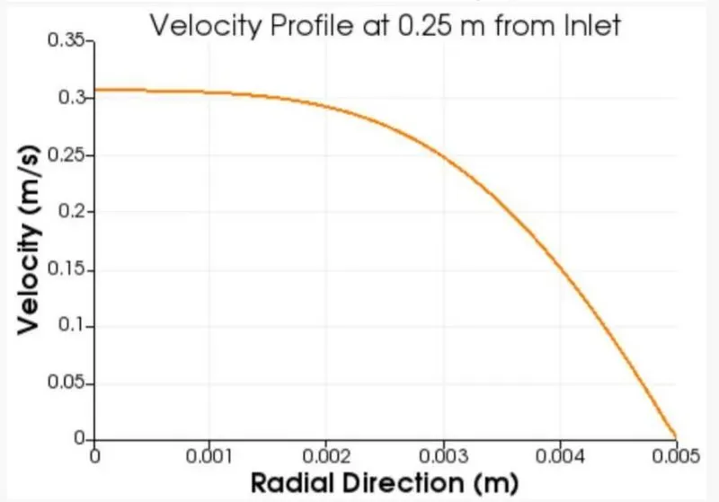
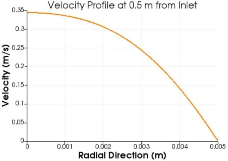
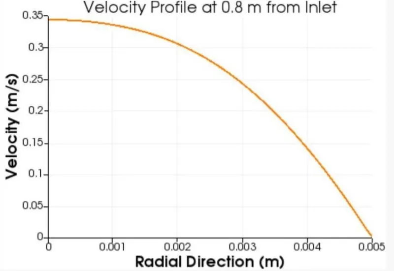
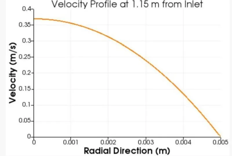
VELOCITY PROFILE:
SHEAR STRESS:
CONCLUSION:
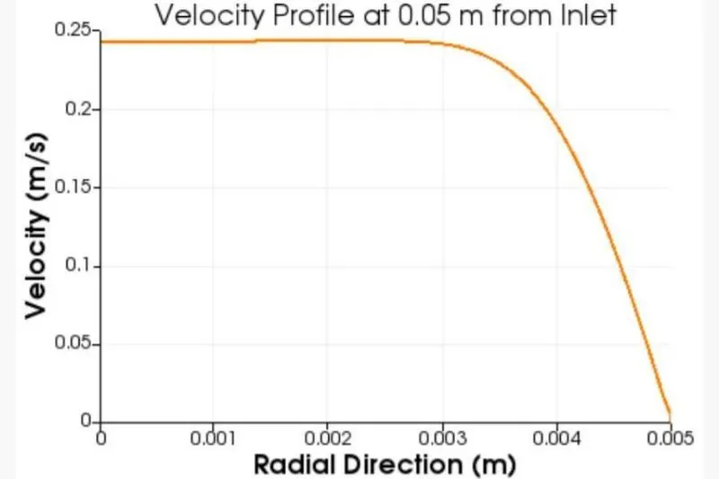
1. The velocity profiles changes until the flow is fully developed.
2. The entry length for the flow is 1.2m After this distance from inlet, the velocity attains its characteristic parabola type shape and does not change any further.
3. The velocity profile obtained is parabolic in nature with max velocity attained at the centre of the pipe.
4. Shear Stress increases the friction on the walls of the pipe because of the which the velocity is maximum at the center of the pipe.
5. The Shear stress plot is obtained after post processing and it is found that the shear stress is maximum at the walls and zero at the centre of the pipe.