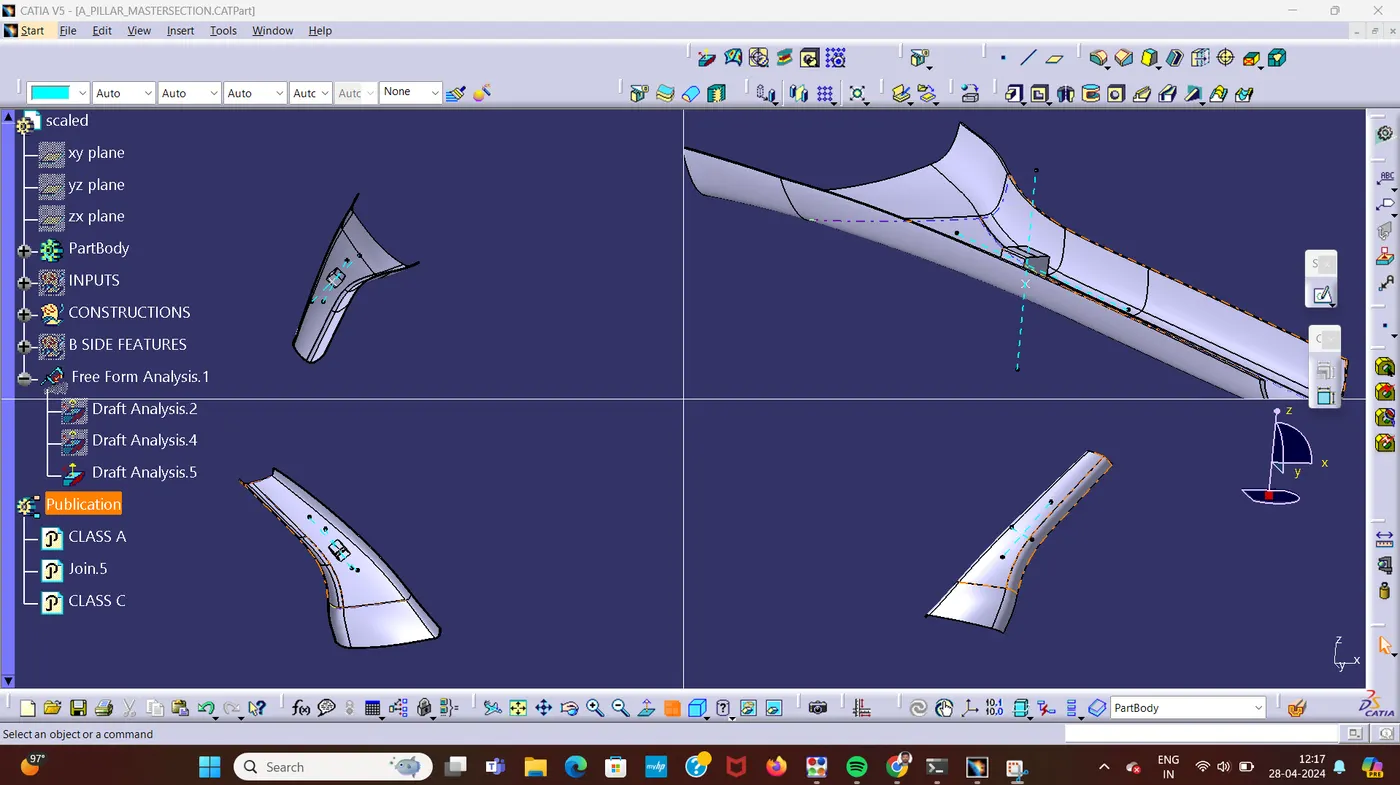
Week 11 - Project - A pillar Design with Master Section
Objective: The goal is to design an A Pillar using a given master section sketch, create a tooling axis, and then perform a draft analysis on the final solid model.
Class A Surface: The Class A surface is the visible surface of the component. It's designed by the styling team to meet aesthetic requirements and serves as a reference for part design engineers as they develop components to meet engineering specifications.
Procedure: Examine the provided surface for continuity using the Join or Boundary commands to ensure that it is smooth and free of gaps.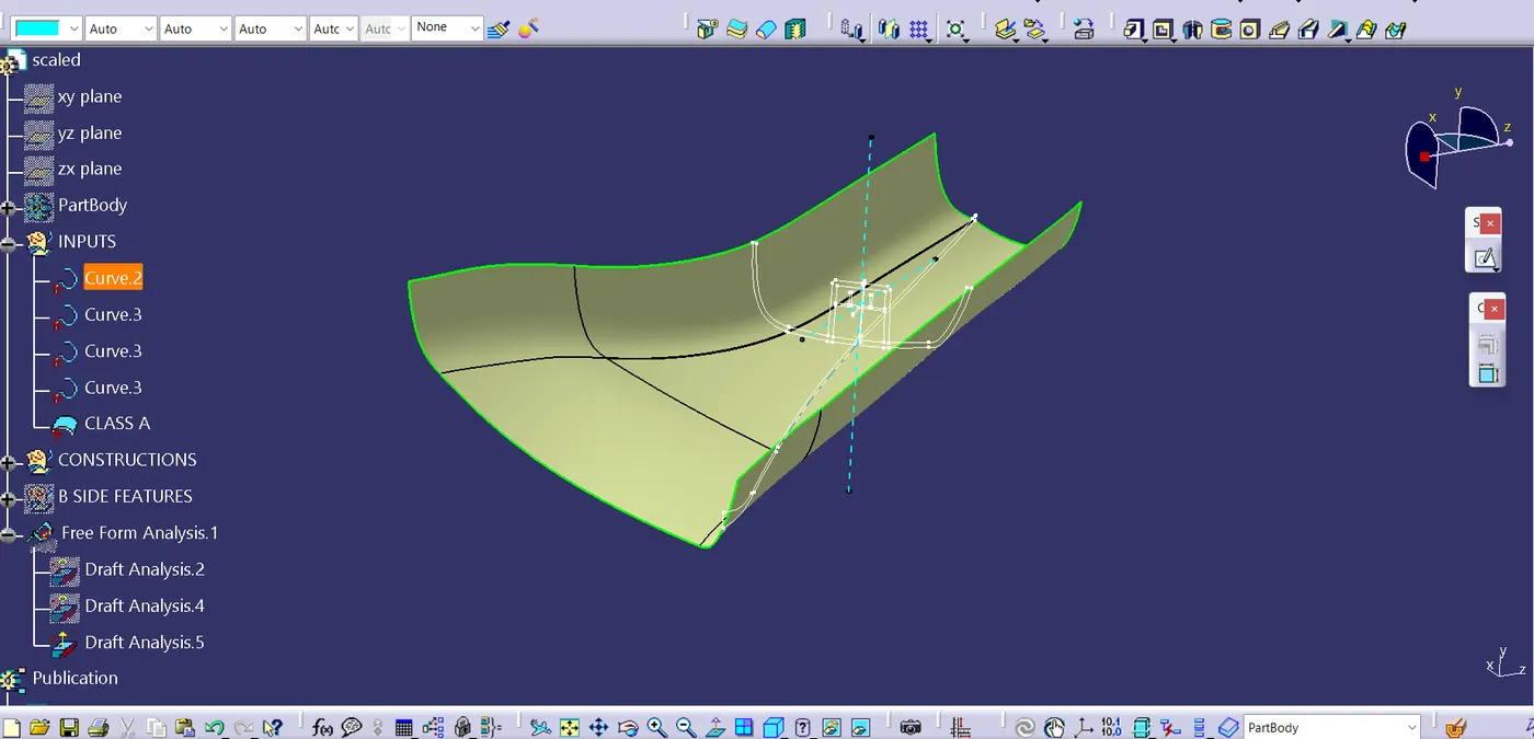
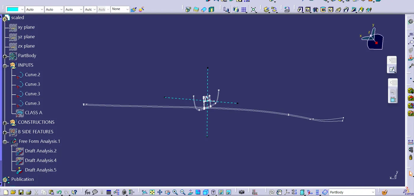
Tooling Axis - Bisecting Line Method: The bisecting line method is a technique used to establish a proper tooling axis. This method involves creating a "dummy" tooling axis and then drawing lines to either bisect them or detect if they are parallel, indicating alignment. The tooling axis should provide a clear path for the tool to remove the part from the mold without any obstructions.
To apply this method, intersect the component surface with a suitable plane to verify its "toolability." This creates an intersection sketch with two lines. By bisecting these lines, you can determine a third line, which acts as the tooling axis, ensuring it meets production requirements.
Side Core Axis: Side cores are used when parts have features that are not aligned with the primary tooling axis, like undercuts or sidewalls. Using the same bisecting line method, or the master section, create an axis that provides adequate clearance for the side core or "dog house." This side core axis will ensure proper molding and demolding without compromising the part's integrity.
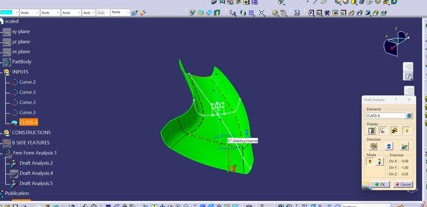
Draft Analysis Overview:
Draft analysis is a technique used in design and manufacturing to ensure that a part can be easily removed from a mold without damage. It involves checking the angle of surfaces relative to a specific direction, usually a tooling axis.
Here’s how draft analysis generally works:
-
Set the Reference Axis: Define a reference axis, typically the tooling axis, to establish the direction from which you will evaluate the draft angles.
-
Align the Compass: Use a compass or similar tool to align with the reference axis. Lock it in place to ensure a consistent orientation throughout the analysis.
-
Analyze the Draft: Apply the draft analysis tool to the surfaces you want to check. The software will color-code the surfaces based on their draft angles, showing which areas meet or fail to meet the required draft criteria.
-
Interpret the Results: Examine the color-coded results to determine if all areas of the part have the correct draft angles for easy removal from the mold. Areas with insufficient draft may need design adjustments to meet manufacturing requirements.
Using this general approach, you can conduct a draft analysis on any part to ensure it meets manufacturing standards for injection molding or other processes requiring draft angles.
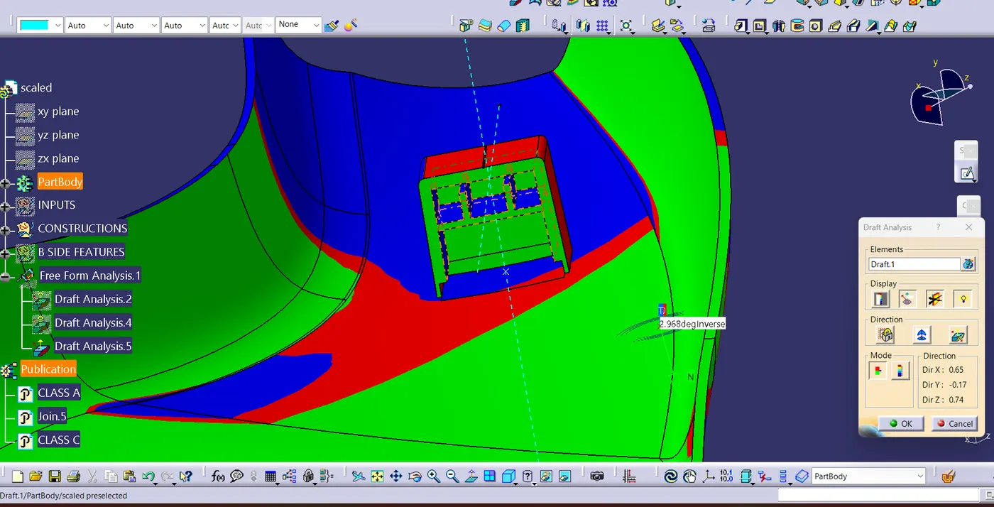
Dog House in Plastic Design
A dog house is a structural feature in plastic components, providing support, alignment, or attachment points. It often contains snaps, locators, or screw bosses to strengthen the assembly.
Purpose Dog houses help avoid sink marks on Class-A surfaces caused by screw bosses and address issues related to attaching bosses to other components. They are usually located on the B-surface.
Draft Analysis Conducting a draft analysis on dog houses is essential to ensure they can be ejected from molds without damage or deformation.
Design Guidelines
- Thickness (C): About 40% of the main wall thickness (T).
- Minimum Width: At least 12 mm.
- Height (B): Between 3 and 6 mm.
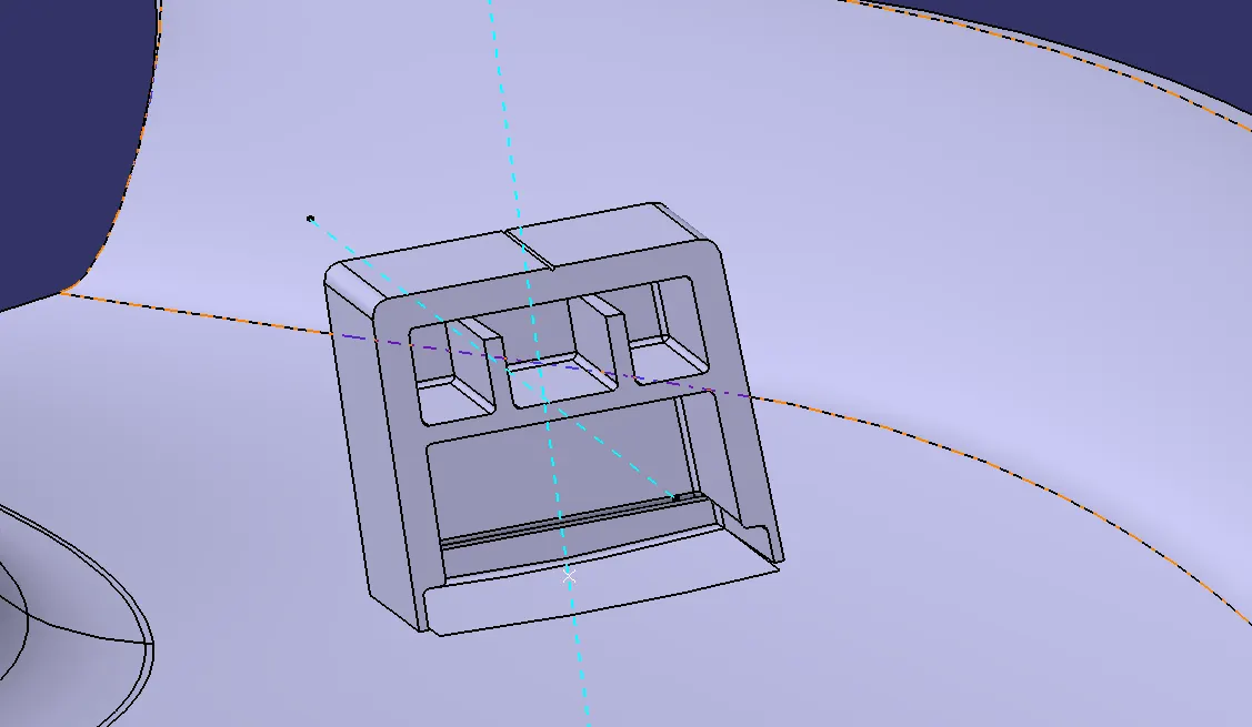
- Final out put